HAL Id: tel-01753845
https://tel.archives-ouvertes.fr/tel-01753845
Submitted on 29 Mar 2018HAL is a multi-disciplinary open access
archive for the deposit and dissemination of sci-entific research documents, whether they are pub-lished or not. The documents may come from teaching and research institutions in France or
L’archive ouverte pluridisciplinaire HAL, est destinée au dépôt et à la diffusion de documents scientifiques de niveau recherche, publiés ou non, émanant des établissements d’enseignement et de recherche français ou étrangers, des laboratoires
Jason Chevrie
To cite this version:
Jason Chevrie. Flexible needle steering using ultrasound visual servoing. Signal and Image processing. Université Rennes 1, 2017. English. �NNT : 2017REN1S098�. �tel-01753845�
ANN ´EE 2017
TH `ESE / UNIVERSIT ´E DE RENNES 1
sous le sceau de l’Universit´e Bretagne Loirepour le grade de
DOCTEUR DE L’UNIVERSIT ´E DE RENNES 1
Mention : Traitement du Signal et T´el´ecommunicationsEcole doctorale MathSTIC
Jason Chevrie
Pr´epar´ee `a l’unit´e de recherche IRISA – UMR6074
Institut de Recherche en Informatique et Syst`emes Al´eatoires
Composante universitaire ISTIC
Flexible Needle
Steering
using Ultrasound
Visual Servoing
Th`ese soutenue `a Rennes le 13 d´ecembre 2017 devant le jury compos´e de : Philippe POIGNET
Professeur, Universit´e de Montpellier / Rapporteur
Nicolas ANDREFF
Professeur, Universit´e de Franche-Comt´e / Rapporteur
Bernard BAYLE
Professeur, Universit´e de Strasbourg / Pr´esident
Sarthak MISRA
Full professor, University of Twente / Examinateur
Alexandre KRUPA
Charg´e de recherche, Inria Rennes / Directeur de th`ese
Marie BABEL
À mes parents. Mêler robots et médical ne m’a pas attiré par hasard.
Acknowledgments
There are many people that I want to thank for making the realization of this thesis such a great experience. I have never really felt at ease telling my life and my feelings, so I will keep it short and hope to make it meaningful. I would first like to deeply thank Alexandre Krupa and Marie Babel for the supervision of this work. I greatly appreciated the freedom and trust they gave me to conduct my research as well as their guidance, feedback and support at the different stages of this thesis: from peaceful periods to harder times when I was late just a few hours before submission deadlines.
I am really grateful to Philippe Poignet and Nicolas Andreff for the time they took to review my manuscript within the tight schedule that was given to them. I would also like to thank them along with Bernard Bayle and Sarthak Misra for being members of my thesis committee and for providing interesting feedback and discussions on my work to orient my future research. Additional thanks go to Sarthak for the great opportunity he gave me to spend some time in the Netherlands at the Surgical Robotics Laboratory. I would also like to thank the other members of this lab for their welcome, and especially Navid for the time we spent working together.
I would like to express my gratitude to François Chaumette for introduc-ing me the Lagadic team months before I started this thesis, which gave me the desire to work there. Many thanks go to all the members and ex-members of this team that I had the pleasure to meet during these years at IRISA. A bit for their help with my work, but mostly for the great atmosphere during all the coffee/tea/lunch breaks and the various out-of-office activities. The list has become too long to mention everyone separately, but working on this thesis during these years would not have been such a great pleasure without all of the moments we spent together, and I hope this can continue.
I would also like to thank all my friends from Granville, Cachan or Rennes, who all contributed to the success of this thesis, consciously or not. A special thank you to Rémi, for various reasons in general, but more specifically here for being among the very few people to proof-read a part of this manuscript and give some feedback.
Finally, my warmest thanks go to my family for their continuous support and encouragements during all this time, before and during the thesis.
Résumé en Français
Les procédures cliniques mini-invasives se sont largement étendues durant ce dernier siècle. La méthode traditionnellement utilisées pour traiter un patient a longtemps été de recourir à la chirurgie ouverte, qui consiste à faire de larges incisions dans le corps pour pouvoir observer et manipuler ses structures internes. Le taux de succès de ce genre d’approche est tout d’abord limité par les lourdes modifications apportées au corps du patient, qui mettent du temps à guérir et peuvent entrainer des complications après l’opération. Il s’ensuit également un risque accru d’infection dû à l’exposition des tissues internes à l’environnement extérieur. Au contraire, les procédures mini-invasives ne requièrent qu’un nombre limité de petites incisions pour accéder aux organes. Le bien-être général du patient est donc amélioré grâce à la réduction des douleurs post-opératoires et la limitation de la présence de larges cicatrices. Le temps de rétablissement des patients est également grandement réduit [EGH+13], en même temps que les risques d’infection [GGSea14], ce qui conduit à de meilleurs taux de succès des opérations et une réduction des coûts pour les hôpitaux.
Lorsque la chirurgie ouverte était nécessaire avant l’introduction de l’ima-gerie médicale, diagnostique et traitement pouvaient faire partie d’une seule et même opération, pour tout d’abord voir les organes et ensuite planifier et effectuer l’opération nécessaire. Les rayons X ont été parmi les premiers moyens découverts pour permettre l’obtention d’une vue anatomique de l’intérieur du corps sans nécessiter de l’ouvrir. Plusieurs modalités d’imagerie ont depuis été développées et améliorées, parmi lesquelles la tomodensito-métrie (TDM) [Hou73], l’imagerie par résonance magnétique (IRM) [Lau73] et l’échographie [WR52] sont maintenant largement utilisées dans le domaine médical.
Au-delà des capacités de diagnostic accrues qu’elle offre, l’imagerie médi-cale a joué un rôle important dans le développement de l’approche chirur-gicale mini-invasive. Observer l’intérieur du corps est nécessaire au succès d’une intervention chirurgicale, afin de voir les tissus d’intérêt et la posi-tion des outils chirurgicaux. De part la nature même de la chirurgie mini-invasive, une ligne de vue directe sur l’intérieur du corps n’est pas possible et il est donc nécessaire d’utiliser d’autres moyens d’observation visuelle, tels que l’insertion d’endoscope ou des techniques d’imagerie anatomique.
Chaque technique a ses propres avantages et inconvénients. Les endoscopes utilisent des caméras, ce qui offre une vue similaire à un œil humain. Les images sont donc faciles à interpréter, cependant il n’est pas possible de voir à travers les tissus. À l’opposé, l’imagerie anatomique permet de vi-sualiser l’intérieur des tissus, mais un entrainement spécifique des médecins est nécessaire pour l’interprétation des images obtenues. La tomodensito-métrie utilise des rayons X, qui sont des radiations ionisantes, ce qui limite néanmoins le nombre d’images qui peuvent être acquises afin de ne pas ex-poser le patient à des doses de rayonnement trop importantes [SBA+09]. L’équipe médicale doit également rester en dehors de la salle où se trouve le scanner pendant la durée d’acquisition. D’un autre côté l’IRM utilise des radiations non-invasives et fournit également des images de haute qualité, avec une grande résolution et un large champ de vue. Cependant ces deux modalités imposent de sévères contraintes, telles qu’un long temps nécessaire pour obtenir une image ou un équipement coûteux et encombrant qui limite l’accès au patient. Dans ce contexte l’échographie est une modalité de choix grâce à sa capacité à fournir une visualisation en temps réel des tissus et des outils chirurgicaux en mouvement. De plus, elle est non-invasive et ne requière que des scanners légers et des sondes facilement manipulables.
Des outils longilignes sont souvent utilisés pour les procédures mini-invasives afin d’être insérés à travers de petites incisions réalisées à la surface du patient. En particulier les aiguilles ont été utilisées depuis longtemps pour extraire ou injecter des substances directement dans le corps. Elles procurent un accès aux structures internes tout en ne laissant qu’une faible marque dans les tissus. Pour cette raison elles sont des outils de premier choix pour une invasion minimale et permettent d’atteindre de petites structures dans des régions profondes du corps. Cependant les aiguille fines peuvent présenter un certain niveau de flexibilité, ce qui rend difficile le contrôle précis de leur tra-jectoire. Couplé au fait qu’une sonde échographique doit être manipulée en même temps que le geste d’insertion d’aiguille, la procédure d’insertion peut rapidement devenir une tâche ardue qui requière un entrainement spécifique des cliniciens. En conséquence, le guidage robotisé des aiguilles est devenu un vaste sujet de recherche pour fournir un moyen de faciliter l’intervention des cliniciens et augmenter la précision générale de la procédure.
La robotique médicale a pour but de manière générale de concevoir et contrôler des systèmes mécatroniques afin d’assister les cliniciens dans leur tâches. L’objectif principal étant d’améliorer la précision, la sécurité et la répétabilité des opérations tout en réduisant leur durée [TS03]. Cela peut grandement bénéficier aux procédures d’insertion d’aiguille en particulier, pour lesquelles la précision est bien souvent cruciale pour éviter les erreurs de ciblage et la répétition inutile d’insertions. L’intégration d’un système robotique dans les blocs opératoires reste un grand défi en raison des con-traintes cliniques et de l’acceptation du dispositif technique par le personnel médical. Parmi les différentes conceptions qui ont été proposées, certains
sys-MOTIVATIONS CLINIQUES
tèmes présentent plus de chances de succès que d’autres. De tels systèmes doivent offrir soit une assistance au chirurgien sans modifier de manière sig-nificative le déroulement de l’opération soit des bénéfices clairs à la fois sur la réussite de l’opération et sur les conditions opératoires du chirurgien. C’est le cas par exemple des systèmes d’amélioration des images médicales ou de suppression des tremblements ou encore des systèmes télé-opérés. Pour les procédures d’insertion d’aiguille, cela consisterait principalement à fournir un monitoring en temps réel du déroulement de l’insertion ainsi qu’un sys-tème robotique entre le patient et la main du chirurgien servant à assister le processus d’insertion. À cet égard, un système robotique guidé par échogra-phie est un bon choix pour fournir une imagerie intra-opératoire en temps réel et une assistance pendant l’opération.
Motivations cliniques
Les aiguilles sont largement utilisées dans une grande variété d’actes médi-caux pour l’injection de substances ou le prélèvement d’échantillons de tissus ou de fluides directement à l’intérieur du corps. Alors que certaines procé-dures ne nécessitent pas un placement précis de la pointe de l’aiguille, comme les injections intramusculaires, le résultat des opérations sensibles dépend grandement de la capacité à atteindre une cible précise à l’intérieur du corps. Dans la suite nous présentons quelques applications pour lesquelles un ciblage précis et systématique est crucial pour éviter des conséquences dramatiques et qui pourraient grandement bénéficier d’une assistance robotisée.
Biopsies pour le diagnostic de cancer
Le cancer est devenu une des causes majeures de mortalité dans le monde avec 8.2 millions de décès dus au cancer estimés à travers le monde en 2015 [TBS+15]. Parmi les nombreuses variétés de cancer, le cancer de la prostate est l’un des plus diagnostiqués parmi les hommes et le cancer du sein parmi les femmes, le cancer du poumon étant aussi une cause majeure de décès pour les deux. Cependant la détection précoce des cancers peut améliorer la probabilité de succès d’un traitement et diminuer le taux de mortalité. Indépendamment du type de tumeur, la biopsie est la méthode de diagnos-tic traditionnellement utilisée pour confirmer la malignité de tissus suspects. Elle consiste à utiliser une aiguille pour prélever un petit échantillon de tissu à une position bien définie à des fins d’analyse. Le placement précis de l’aiguille est d’une importance capitale dans ce genre de procédure afin d’éviter une erreur de diagnostic due au prélèvement de tissus sains autour de la région suspectée. Les insertions manuelles peuvent donner des résul-tats variables qui dépendent du clinicien effectuant l’opération. Le guidage robotique de l’aiguille a donc le potentiel de grandement améliorer les per-formances des biopsies. Un retour échographique est souvent utilisé, par
exemple pour le diagnostic du cancer de la prostate [KSH14]. La tomod-ensitométrie est également un bon choix pour le cancer du poumon et un système robotique est d’une grande aide afin de compenser les mouvements de respiration [ZTK+13]. Les systèmes robotiques peuvent également être utilisés afin de maintenir et modifier la position des tissus pour aligner une tumeur potentielle avec l’aiguille, particulièrement dans le cas de biopsies du cancer du sein [MSP09].
Curiethérapie
La curiethérapie a prouvé être un moyen efficace pour traiter le cancer de la prostate [GBS+01]. Elle consiste à placer de petits grains radioactifs dans la tumeur à détruire. Cette procédure nécessite le placement précis et uni-forme d’une centaine de grains, ce qui peut prendre du temps et requière une grande précision. Les conséquences d’un mauvais placement peuvent être dramatiques par la destruction de structures sensibles alentours, comme la vessie, le rectum, la vésicule séminale ou l’urètre. L’insertion est habituelle-ment effectuée sous échographie trans-rectale, ce qui peut permettre d’utiliser un système robotisé pour accomplir des insertions précises et répétées sous guidage échographique [HBLT12] [SSK+12] [KSH14]. L’IRM est également couramment utilisée et fait l’objet de recherche pour une utilisation avec un système robotique [SAIF16].
Cancer du foie
Après le cancer du poumon, le cancer du foie est la cause majeure de décès dus au cancer chez l’homme, avec environ 500000 décès chaque année [TBS+15]. L’ablation par radiofréquence est la principale modalité thérapeu-tique utilisée pour effectuer une ablation de tumeur du foie [LCPC09]. Une sonde d’ablation, apparentée à une aiguille, est insérée dans le foie et génère de la chaleur pour détruire localement les tissus. Guider précisément la sonde sous guidage visuel peut éviter la destruction inutile de trop de tis-sus. Les biopsies du foie peuvent également être effectuées en utilisant des aiguilles de ponction percutanée [GN99]. Utiliser un guidage robotisé sous modalité échographique pourrait permettre d’éviter de multiple insertions qui augmentent les saignements hépatiques et peuvent avoir de graves con-séquences.
Contributions
Dans cette thèse nous traitons du contrôle automatique d’un système robo-tique pour l’insertion d’une aiguille flexible dans des tissus mous sous guidage échographique. Traiter ce sujet nécessite de considérer plusieurs points. Tout d’abord l’interaction entre l’aiguille et les tissus doit être modélisée afin
CONTRIBUTIONS
de pouvoir prédire l’effet du système robotique sur l’état de la procédure d’insertion. Le modèle doit être capable de représenter les différents aspects de l’insertion et être à la fois suffisamment simple pour être utilisé en temps réel. Une méthode de contrôle doit également être conçue pour permettre de diriger la pointe de l’aiguille vers sa cible tout en maintenant la sécurité de l’opération. Le ciblage précis est rendu difficile par le fait que les tissus biologiques peuvent présenter une grande variété de comportements. Guider l’aiguille introduit aussi nécessairement une certaine quantité de dommages aux tissus, de telle sorte qu’un compromis doit être choisi entre le succès du ciblage et la réduction des dommages. Les mouvements physiologiques du patient peuvent également être une source importante de mouvement de la région ciblée et doivent aussi être pris en compte pour éviter d’endommager les tissus ou l’aiguille. Finalement la détection fiable de l’aiguille dans les im-ages échographiques est un pré-requis pour pouvoir guider l’aiguille dans la bonne direction. Cependant cette tâche est rendue difficile par la faible qual-ité de la modalqual-ité échographique. Afin de relever ces défis, nous apportons plusieurs contributions dans cette thèse, qui sont :
• Deux modèles 3D de l’interaction entre une aiguille flexible à pointe biseautée et des tissus mous. Ces modèles sont conçus pour permettre un calcul en temps réel et fournir une représentation 3D de l’ensemble du corps de l’aiguille pendant son insertion dans des tissus en mouve-ment.
• Une méthode d’estimation des mouvements latéraux des tissus en util-isant uniquement des mesures disponibles sur le corps de l’aiguille. • Une méthode de suivi d’aiguille flexible dans des volumes
échogra-phiques 3D qui prend en compte les artefacts inhérents à la modalité échographique.
• La conception d’une approche de contrôle pour un système robotique insérant une aiguille flexible dans des tissus mous. Cette approche a été développée de manière à être facilement adaptable à n’importe quels composants matériels, que ce soit le type d’aiguille, le système robotique utilisé pour le contrôle des mouvements de l’aiguille ou la modalité de retour utilisée pour obtenir des informations sur l’aiguille. Elle permet également de considérer des stratégies de contrôle hy-brides, comme la manipulation des mouvements latéraux appliqués à la base de l’aiguille ou le guidage de la pointe de l’aiguille exploitant une géométrie asymétrique de cette pointe.
• La validation ex-vivo des méthodes proposées en utilisant diverses plateformes expérimentales et différents scénarios afin d’illustrer la flex-ibilité de notre approche de commande pour différents cas d’insertion d’aiguille.
Organisation de la thèse
Le contenu de chaque chapitre de cette thèse est à présent détaillé dans la suite.
Chapitre 1: Nous présentons le contexte clinique et scientifique dans lequel s’inscrit cette thèse. Nous définissons également nos objectifs principaux et présentons les différents défis associés. Le matériel utilisé dans les différentes expériences effectuées est également présenté.
Chapitre 2: Nous présentons une vue d’ensemble des modèles d’interaction aiguille/tissus. Un état de l’art des différentes familles de modèles est tout d’abord fourni, avec un classement des modèles selon leur complexité et leur utilisation prévue en phase pre-opératoire ou intra-opératoire. Nous proposons ensuite une première contribution sur la modélisation 3D d’une aiguille à pointe biseautée, qui consiste en deux modèles numériques pou-vant être utilisés pour des applications en temps-réel et offrant la possibilité de considérer le cas de tissus en mouvement. Les performances des deux modèles sont évaluées et comparées à partir de données expérimentales. Chapitre 3: Nous traitons le problème du suivi du corps d’une aiguille incurvée dans des volumes échographiques 3D. Les principes généraux de l’acquisition d’images échographiques sont tout d’abord décrits. Ensuite nous présentons une vue d’ensemble des algorithmes récents de détection et de suivi utilisés pour la localisation du corps de l’aiguille ou seulement de sa pointe dans des séquences images échographiques 2D ou 3D. Nous proposons ensuite une nouvelle contribution au suivi 3D d’une aiguille en exploitant les artefacts naturels apparaissant autour de l’aiguille dans des volumes 3D. Finalement nous proposons également une méthode de mise à jour de notre modèle d’aiguille en utilisant les mesures acquises pendant l’insertion pour prendre en compte les mouvements latéraux des tissus. Le modèle mis à jour est utilisé pour prédire la nouvelle position de l’aiguille et améliorer le suivi de l’aiguille dans le prochain volume 3D acquis.
Chapitre 4: Nous nous concentrons sur le sujet principal de cette thèse qui est le contrôle robotisé d’une aiguille flexible insérée dans des tissus mous sous guidage visuel. Nous dressons tout d’abord un état de l’art sur le guidage d’aiguilles flexibles, depuis le contrôle bas niveau de la trajectoire de l’aiguille jusqu’à la planification de cette trajectoire. Nous présentons en-suite la contribution principale de cette thèse, qui consiste en une approche de contrôle pour le guidage d’aiguille qui a la particularité d’utiliser plusieurs stratégies de guidage et qui est indépendante du type de manipulateur robo-tique utilisé pour actionner l’aiguille. Les performances de cette approche de
ORGANISATION DE LA THÈSE
contrôle sont finalement illustrées au travers de plusieurs scénarios expéri-mentaux ex-vivo utilisant des caméras ou l’échographie 3D comme retour visuel.
Chapitre 5: Nous considérons le problème des mouvements du patient pendant la procédure d’insertion d’aiguille. Nous présentons d’abord une vue d’ensemble des techniques de compensation de mouvement pendant l’insertion d’une aiguille. Notre approche de contrôle introduite dans le chapitre 4 est ensuite étendue et nous exploitons la méthode de mise à jour de modèle proposée dans le chapitre 3 afin de se charger de l’insertion d’une aiguille dans des tissus subissant des mouvements latéraux. Nous fournissons les résultats expérimentaux obtenus en utilisant notre approche de contrôle pour guider l’insertion d’une aiguille dans un fantôme constitué de tissus mous en mouvement. Ces expériences ont été réalisées en utilisant plusieurs modalités de retour d’information, fournies par un capteur d’efforts, un cap-teur électromagnétique et l’échographie 2D.
Conclusion: Finalement nous concluons cette thèse et présentons des per-spectives pour de possibles extensions et applications.
Contents
Résumé en Français i
1 Introduction 1
1.1 Clinical motivations . . . 3
1.1.1 Biopsy for cancer diagnosis . . . 3
1.1.2 Brachytherapy . . . 3 1.1.3 Liver cancer . . . 4 1.2 Scientific context . . . 4 1.2.1 Robotic designs . . . 4 1.2.2 Sensor feedback . . . 7 1.2.3 Objectives . . . 9 1.3 Challenges . . . 9 1.4 Contributions . . . 11 1.5 Experimental context . . . 11 1.5.1 Robots . . . 12
1.5.2 Visual feedback systems . . . 14
1.5.3 Phantoms . . . 15 1.5.4 Workstations . . . 15 1.5.5 Needles . . . 16 1.5.6 Force sensor . . . 16 1.5.7 Electromagnetic tracker . . . 17 1.6 Thesis outline . . . 17
2 Needle insertion modeling 19 2.1 Kinematic modeling . . . 20
2.2 Finite element modeling . . . 23
2.3 Mechanics-based modeling . . . 24
2.4 Generic model of flexible needle . . . 27
2.4.1 Needle tissue interaction model with springs . . . 27
2.4.2 Needle tissue interaction model using two bodies . . . 32
2.5 Validation of the proposed models . . . 35
3 Needle localization using ultrasound 47
3.1 Introduction . . . 48
3.2 Ultrasound imaging . . . 49
3.2.1 Physics of ultrasound . . . 49
3.2.2 Reconstruction in Cartesian space . . . 53
3.2.2.1 Reconstruction of 2D images . . . 54
3.2.2.2 Reconstruction of 3D volumes . . . 57
3.3 Needle detection in ultrasound . . . 60
3.3.1 Ultrasound needle artifacts . . . 60
3.3.2 Needle detection algorithms . . . 63
3.4 Intensity-based needle tracking . . . 66
3.4.1 Tracking with camera feedback . . . 66
3.4.2 Iterative tracking using ultrasound needle artifacts . . 69
3.4.3 Experimental validation . . . 73
3.5 Tissue motion estimation . . . 78
3.5.1 Multimodal estimation . . . 78
3.5.1.1 Bayesian filtering . . . 78
3.5.1.2 Particle filter . . . 81
3.5.1.3 Kalman filters . . . 82
3.5.2 Tissue motion estimation using unscented Kalman filter 87 3.5.2.1 Evolution equation . . . 87
3.5.2.2 Measure equation . . . 89
3.6 Tissue update validation . . . 92
3.6.1 Update from force and position feedback . . . 92
3.6.2 Update from position feedback . . . 99
3.6.3 Needle tracking in 3D US with moving soft tissues . . 109
3.7 Conclusion . . . 115
4 Needle steering 117 4.1 Steering strategies . . . 118
4.1.1 Tip-based needle steering . . . 118
4.1.2 Needle steering using base manipulation . . . 120
4.1.3 Tissue manipulation . . . 122
4.2 Needle tip trajectory . . . 122
4.2.1 Path planning . . . 123
4.2.2 Reactive control . . . 125
4.3 Needle steering framework . . . 126
4.3.1 Task function framework . . . 127
4.3.2 Stability . . . 131
4.3.3 Task Jacobian matrices . . . 132
4.3.4 Task design for needle steering . . . 134
4.3.4.1 Targeting tasks design . . . 134
4.3.4.2 Safety tasks design . . . 142
CONTENTS
4.4.1 Insertion under camera feedback . . . 147
4.4.1.1 Switching base manipulation and duty-cycling 147 4.4.1.2 Safety task comparison . . . 154
4.4.1.3 Robustness to modeling errors . . . 164
4.4.2 Insertion under US guidance . . . 167
4.5 Conclusion . . . 175
5 Needle insertion with tissue motion compensation 177 5.1 Tissue motion during needle insertion . . . 178
5.2 Motion compensation in our task framework . . . 179
5.3 Target tracking in ultrasound . . . 182
5.3.1 Target tracking in 2D ultrasound . . . 182
5.3.2 Target tracking validation in 2D ultrasound . . . 185
5.4 Motion compensation using force feedback . . . 188
5.4.1 Force sensitivity to tissue motions . . . 188
5.4.2 Needle insertion with motion compensation . . . 194
5.5 Conclusion . . . 206
Conclusion 207 Conclusions . . . 207
Perspectives . . . 210
List of publications 215
A Force sensor calibration 217
Bibliography 241
List of acronyms 243
Chapter 1
Introduction
Minimally invasive procedures have greatly expanded over the past century. The traditional way to cure a patient has long been to resort to open surgery, which consists in making a large cut in the body to observe and manipulate its intern parts. The success rate of such an approach is first limited by the heavy modifications made to the body, which take time to heal and can lead to complications after the surgery. There is also a greater risk of subsequent infections due to the large exposure of the inner body to the outside environment. On the contrary, minimally invasive procedures only require a limited number of small incisions to access the organs. Therefore, this improves the overall well-being of the patient thanks to reduced post-operative pain and scarring. The recovery time of the patient is also greatly reduced [EGH+13] along with the risk of infections [GGSea14], resulting in higher success rates for the operations and a cost reduction for the hospitals. When open surgery was necessary before the introduction of medical imaging, diagnosis and treatment could be two parts of a same interven-tion, in order to first see the organs and then plan and perform the required surgery. X-rays were among the first tools discovered to provide an anatom-ical view of the inside of the body without needing to open it. Several imag-ing modalities have since been developed and improved for medical purposes, among which computerized tomography (CT) [Hou73], magnetic resonance imaging (MRI) [Lau73] and ultrasound (US) [WR52] are now widely used in the medical domain.
Beyond the improved diagnosis capabilities that it offers, medical imag-ing has played an important role in the development of the minimally in-vasive surgery approach. Viewing the inside of the body is necessary to perform successful surgical interventions, in order to see the tissues of inter-est and the position of the surgical tools. Due to the nature of minimally invasive surgery, a direct view is not possible and it is thus necessary to use other means of visual observation, such as endoscope insertion or anatomical imaging techniques. Each technique has its own advantages and drawbacks. Endoscopes use cameras, which offer the same view as a human eye. The
images are thus easy to interpret, however it is not possible to see through the tissues. On the other hand, anatomical imaging allows a visualization of the inside of the tissues, but a specific training of the physicians is required in order to interpret the images. CT imaging uses X-rays, which are ionizing radiations, therefore limiting the number of images that can be acquired in order not to expose the patient to a too high amount of radiations [SBA+09]. The medical staff should also remain outside the scanner room during the acquisition. On the other hand MRI makes use of non-invasive radiations and also provides high quality images, with high resolution and large field of view. However they impose severe constraints, such as a long time to acquire an image or an expensive and bulky scanner that limits the access to the patient. In this context, ultrasonography is a modality of choice for intra-operative imaging, due to its ability to provide a real-time visualization of tissues and tools in motion. Additionally, it is non-invasive and requires lightweight scanners and portable probes.
Slender tools are often used for minimally invasive procedures in order to be inserted through narrow incisions made at the surface of the patient. In particular, needles have been used since long times to extract or inject substances directly inside the body. They provide an access to inner struc-tures while leaving only a very light wound in the tissues. For this reason they are tools of first choice for minimal invasiveness that can allow reach-ing small structures in deep regions. Thin needles can however exhibit a certain amount of flexibility, which makes accurate steering of the needle trajectory more complicated. Coupled to the handling of an US probe at the same time as the needle insertion gesture, the insertion procedure can become a challenging task which requires specific training of the clinician. Consequently, robotic needle steering has become a vast subject of research to ease the intervention of the clinician and to improve the overall accuracy of the procedure.
Medical robotics in general aims at designing and controlling mechatron-ics systems to assist the clinicians in their tasks. The main goal is to im-prove the accuracy, safety and repeatability of the operations and to reduce their duration [TS03]. It can greatly benefit the needle insertion procedures for which accuracy is often crucial to avoid mistargeting and unnecessary repeated insertions. However, the integration of a robotic system in the operating room remains a great challenge due to clinical constraints and ac-ceptance of the technical device from the medical staff. Among the many designs that have been proposed, some systems have better chances of being accepted. Such systems should either assist the surgeon without requiring a lot of modifications of the clinical workflow or should procure clear benefits for both the success of the operation and the operating conditions of the surgeon. This is for example the case of imaging enhancement and tremor cancellation systems, or of tele-operated systems. For needle insertions pro-cedures, this would mainly consists in providing a real-time monitoring of the
1.1. CLINICAL MOTIVATIONS
state of the insertion as well as a robotic system between the patient and the hand of the surgeon assisting at the insertion process. In this context, an US-guided robotic system is a great choice to provide real-time intra-operative imaging and assistance during the operation.
1.1
Clinical motivations
Needles are widely used in a great variety of medical acts for the injection of substances or the sampling of fluids or tissues directly inside the body. While some procedures do not require an accurate placement of the needle tip, such as intramuscular injections, the results of sensitive operations highly depend on the ability to reach a precise location inside the body. In the following we present some applications for which systematic accurate targeting is cru-cial to avoid dramatic consequences and which could greatly benefit from a robotic assistance.
1.1.1 Biopsy for cancer diagnosis
Cancer has become one of the major cause of death in the world with 8.2 million cancer deaths estimated worldwide in 2015 [TBS+15]. Among the many types of cancers, prostate cancer is the most diagnosed cancer among men and breast cancer among women, with lung cancer being a leading cause of cancer deaths for both. However early detection of cancer can improve the chance of success of cancer treatment and diminish the mortality rates. Whatever the kind of tumor, biopsies are the traditional diagnostic method used to confirm the malignancy of suspected tissues. It consists in using a needle to get a small sample of tissues at a defined location for analysis pur-poses. The accurate placement of the needle is of paramount importance in this procedure to avoid misdiagnosis due to the sampling of healthy tissues surrounding the suspected lesion. Freehand insertions can give variable re-sults depending on the clinician performing the operation. Therefore, robotic needle guidance under visual feedback has the potential to greatly improve the performances of biopsies. Ultrasound feedback is often used, as for exam-ple for the diagnostic of prostate cancer [KSH14]. Computerized tomography (CT) is also a good choice for lung cancer diagnosis and a robotic system is of great help to compensate for breathing motions [ZTK+13]. Robotic sys-tems can also be used to maintain and modify the position of the tissues to align a suspected tumor with the needle, especially for breast cancer biopsy [MSP09].
1.1.2 Brachytherapy
Brachytherapy has proven to be an efficient way to treat prostate cancer [GBS+01]. It consists in placing small radioactive seeds in the tumors to
destroy. The procedure requires the accurate uniform placement of about a hundred seeds, which can be time consuming and require great accuracy. The consequence of misplacement can be dramatic due to the destruction of surrounding sensitive tissues like bladder, rectum, seminal vesicles or urethra. The insertion is usually performed under transrectal ultrasound, which can allow the use of robotic systems to perform accurate and repetitive insertions under ultrasound (US) guidance [HBLT12] [SSK+12] [KSH14]. Magnetic resonance imaging (MRI) is also commonly used and is the subject of research to explore its use together with a robotic system [SAIF16].
1.1.3 Liver cancer
Liver cancer is the major cause of cancer deaths after lung cancer among men with about 500000 deaths each year [TBS+15]. Radiofrequency ab-lation is the primary therapetic modality to perform liver tumor abab-lations [LCPC09]. An electrode needle is inserted in the liver and generates heat to locally destroy the tissues. Accurately guiding the needle under image-guidance can help avoiding unnecessary tissue destruction. Liver biopsies can also be performed using percutaneous punction needles [GN99]. Per-forming robotic ultrasound (US) guidance could avoid multiple insertions that increase hepatic bleeding and can have dramatic consequences.
1.2
Scientific context
Reaching a specific region in the body without performing open surgery is a challenging task that has been a vast subject of research and developments over the past decades. Many robotic designs have been proposed to achieve this goal. In the following we present a non-exhaustive overview of these different technologies as well as various kinds of sensor modalities that have been developed and used to provide feedback on the medical procedure. We then define where we positioned the work presented in this thesis relative to this context.
1.2.1 Robotic designs
Continuum robots: These systems are snake-like robots consisting of a succession of actively controllable articulations, as can be seen in Fig. 1.1a. They offer a large control over their whole shape and can be used to perform many kinds of operations. Many varieties of designs are possible and the study of such robots is a vast field of research by itself [Wal13][BKRC15]. However their design and control are often complex and their diameter is usually larger than standard needles, which limit the use of such system in practice.
1.2. SCIENTIFIC CONTEXT
(a) (b)
Figure 1.1: Example of (a) continuum robot (taken from [CMC+08]) and (b) concentric tubes (taken from [WRC09]).
Figure 1.2: Illustration of several kinds of needle tip.
Concentric tubes: This kind of robots, also known as active cannulas, is a special kind of continuum robots which consist of a telescopic set of flexible concentric pre-curved tubes that can slide and rotate with respect to each other [WJ10]. Each tube is initially maintained inside the larger tubes and the insertion of such device is performed by successively inserting each set of tubes and leaving in place the outermost tubes one after another, as seen in Fig. 1.1b. They offer additional steering capabilities compared to flexible needles due to the pre-curved nature of each element, while main-taining a relatively small diameter. Furthermore, once the tubes have been deployed, rotation of the different elements allows for controlled deforma-tions of the system all along its body. Although the design can be limited to only one pre-curved stylet placed in an outer straight tube, as was proposed in [OEC+05], some other designs are possible to enable an additional control of the curvature of each tube [CRA16]. As continuum robots, the modeling and control of such systems remain quite complex [DLIB10] [BLH+16].
Needle insertion devices: Many robotic systems have been designed for the insertion of traditional needles and particularly for asymmetric tip nee-dles. Several kinds of asymmetries are possible, as illustrated in Fig. 1.2.
These needles tend to naturally deviate from a straight trajectory, such that the rotation around their shaft plays an important role. Many needle
Figure 1.3: General concept of a needle insertion device (taken from [WMO05]).
insertion systems have been proposed, all being a variant of the same design consisting of one linear stage for the insertion and one rotative stage for needle rotation along and around its main axis [WMO05], as depicted in Fig. 1.3. They are usually designed for a specific kind of intervention, such as prostate interventions under ultrasound (US) imaging [YPZ+07] [HBLT12]. Special robots have also been designed to be compatible with the limitations imposed by computerized tomography (CT) scanners [MGB+04], magnetic resonance imaging (MRI) scanners [MvdSK+17] or both [ZBF+08].
Active needles: Alternatively, many designs have been proposed to re-place traditional needles and provide additional control capabilities over their bending. A needle made of multiple segments that can slide along each other was designed such that the shape of the tip can be modified during the in-sertion [KFRyB11]. A 1 degree of freedom (DOF) actuated needle tip was designed such that it can act as a pre-bent tip needle with variable angle be-tween the shaft and the pre-bent tip [AGL+16]. A similar tendon-actuated needle tip with 2 DOF was also used to allow the orientation of the tip without rotation of the needle around its axis [RvdBvdDM15]. Additional considerations about tip designs can be found in [vdBvGDvdD14]. These needle designs allows a high controllability of the tip trajectory, however, in addition to the increased complexity of the needle itself, they require a special system to be able to control the additional DOF from the needle base.
A combination of different methods can also be made as was done in [SMR+15], where using a succession of cable driven continuum robot, con-centric tubes and beveled-tip needle increases the reachable space and final accuracy of the targeting.
1.2. SCIENTIFIC CONTEXT
(a) (b) (c)
Figure 1.4: Example of special designs of the needle tip: (a) multi-segment needle (taken from [KFRyB11]), (b) one degree of freedom active pre-bent tip (taken from [AGL+16]) and (c) two degrees of freedom active prebent tip (taken from [RvdBvdDM15]).
1.2.2 Sensor feedback
In order to be used for needle insertion assistance, a robotic system should be able to monitor the state of the insertion. Therefore, feedback modal-ities have to be used to provide some information on the needle and the tissues. The choice of the sensors is an important issue that has to be taken into account from the beginning of the conception of the system. Indeed, they should either be directly integrated into the system or they can pose compatibility issues in the case of external modalities. In the following we provide an overview of some feedback modalities currently used or explored for needle insertion procedures.
Shape feedback: The shape of the entire needle can be reconstructed using fiber Bragg grating (FBG) sensors. This kind of sensor consists in several optic fibers integrated in the needle. The light propagates differently in these fibers depending on the curvature of the fiber at certain locations, such that the curvature of the needle can be measured and used to retrieve its shape [PED+10]. This kind of sensor requires a special design of the needle, since the fibers need to follow the same deformations as the needle does.
An electromagnetic (EM) tracker can also be used for the tracking of the position and orientation of a specific point of the needle, which is typically the tip. They provide a great accuracy on the measures and currently available trackers are small enough such that they can fit directly in standard needles. Real-time imaging modalities: Feedback on the needle position is not sufficient for needle insertions since the position of the targeted region must also be known. Using an imaging modality can provide a visual feedback on the position of both the needle and the target. Ultrasound (US) is the
modality of choice for real-time imaging due its fast acquisition rate of 2D or 3D images, good resolution and safety. Special 2.5D US transducers are also the subject of current research to enable a direct detection and display of the needle tip in a 2D US image, even when the tip is outside the imaging plane of the probe [XWF+17]. However, these transducers are currently not commonly available. A limiting factor of US in general is the low quality of the images due to the intrinsic properties of US waves.
On the other hand, computerized tomography (CT)-scan or magnetic resonance imaging (MRI) are used for manual insertions thanks to the high quality of their images and the large field of view that they offer. However, as stated previously, this kind of imaging method can not be used directly for real-time image-guided robotic needle insertion, due to their long acquisition time. They can still be used for non real-time tele-operated robotic control, by alternating between insertion steps and imaging steps, however a single needle insertion can take more than 45 minutes. Tissue motions between two acquisitions is also an issue that requires additional real-time sensors to be compensated for, such as force sensors [MDG+05] or optical tracking [ZTK+13].
On the contrary CT fluoroscopy can be used to acquire real-time images. However, in manual needle insertion this exposes the clinician to a high dose of noxious radiations. This can be avoided by wearing unpractical special shielding or by using a remotely controlled insertion system [SPB+02]. How-ever the patient is still exposed to the high amount of radiations necessary for real-time performances.
Fast MRI acquisition has also recently been explored to perform image-guided needle insertion [PvKL+15]. Decreasing the image size and quality, a 2D image could be acquired with a sufficient resolution every 750 ms. By comparison, the US modality can provide a full 3D volume with similar resolution within the same acquisition time, and 2D US can acquire several tens of images per second.
Force feedback: Force sensors can be used to measure the forces applied to the needle and tissues. Force sensing can be useful to monitor the state of the insertion, for example by detecting the perforation of the different structures that the needle is going through [OSO04]. It can also be used with tele-operated robotic systems to provide a feedback to the clinician [PBB+09] or compensate for tissue motion [JMBG11]. Any kind of force sensors can be used with the US modality, however compatibility issues have to be taken into account for the design of sensors compatible with CT [KPM+14] or MRI [GCBB08].
1.3. CHALLENGES
1.2.3 Objectives
The objective of this thesis is to focus on the robotic steering of traditional flexible needles. These needles are already widely available and used in clinical practice. Moreover they do not require specific hardware, contrary to other special robotic designs, which requires dedicated control hardware and techniques. The idea is then to provide a generic formulation of the different concepts that we introduce, such that our work can be adapted to several kinds of needle tip and rigidity. In this context, the control of the full motion of the needle base should thus be performed, such that it is not limited to flexible beveled-tip needles but can also be used to insert rigid symmetric tip needles. The formulation should also stay as much as possible independent of the actual robotic system used to perform the needle steering. This choice is motivated by the fact that it would ease the clinical acceptance of the method and could be applicable to several robotic systems and medical applications.
Another objective is to focus on the insertion under ultrasound (US) guidance, motivated by the fact that it is already used in current medical practice and does not require any modification of the needle to provide a real-time feedback on its whole shape. For the development and validation of our work, we try to keep in mind some clinical constraints related to the set-up and registration time, which should be as small as possible. Sev-eral other modalities have also to be explored, such as force feedback and electromagnetic (EM) feedback, which can easily be implemented alongside traditional needles and the US modality.
1.3
Challenges
In order to fulfill our objective of performing the ultrasound-guided control of a robotic system for the insertion of a flexible needle in soft tissues, several challenges needs to be addressed. We describe these different challenges in the following.
Interaction modeling: First, the control of the insertion of a flexible needle with a robotic system requires a model of the interaction between the needle and soft tissues. The effect of the inputs of the robotic insertion system on the needle position and effective length have to be modeled as well. The model should be complete to represent the whole body of the needle in 3D as well as the influence of the tip geometry on its trajectory. It should also be generic enough so that it can be easily adaptable to several kinds of needles. Since it is used for intra-operative purposes, it should be able to represent the current state of the insertion, taking into account the effect of potential motions of the tissues on the deformation of the needle. While complex and accurate models of the needle and tissues exist, the complexity
of the modeling must remain reasonable such that real-time performances can be achieved.
Needle control: The control of the trajectory of a flexible needle is a challenging task in itself. The complex interaction of the needle with the tis-sues at its tip and along its shaft is difficult to completely predict, especially because of the great variety of behaviors exhibited by biological tissues. Ac-curately reaching a target requires then to take into account and to exploit the flexibility of the needle and the motion of the tissues. The safety of the operation should also be ensured to avoid excessive damage caused by the needle onto the tissues. This is a difficult task since inserting the needle necessarily introduces a certain amount of tissue cutting, and steering the needle can only be achieved through an interaction of the needle with the tissues.
Tissue motion: Many needle insertion procedures are not performed un-der general anesthesia. As a consequence, physiological motions of the pa-tient can not always be controlled. Papa-tient motions can have several effects on the needle insertion. First it introduces a motion of the targeted region, which should be accounted for in order to avoid mistargeting. The trajec-tory of a flexible needle could also be modified by tissue motions. During manual needle insertion, clinicians can directly see the motion of the skin of the patient and feel the forces applied on the needle and tissues, such that they can easily follow the motions of the patient if needed. A robotic system should also be able to adapt to some motions of the patient while inserting the needle to avoid threatening the safety of the operation. This point represents a great challenge due to the limited perception available for the robotic system.
Needle detection: Accurate localization of the needle in ultrasound (US) images is a necessary condition to be able to control the state of the insertion. The low quality of US images is a first obstacle to the accurate localization of the needle tip. It can greatly vary depending on the tissues being observed and the position of the needle relatively to the US probe. Using 3D US has the advantage that the whole shaft of the needle can be contained in the field of view of the US probe, which is not the case with 2D US. However, even in 3D US the needle is not equally visible at all points due to specific artifacts that can come from the surrounding tissues or from the needle itself. Even if the 3D volume acquisition is relatively fast, the position of the needle in the volume can still greatly vary due to the motion of the patient or of the probe between two acquisitions. Overall needle localization using US feedback represents a challenging task that is still an open issue that has to be addressed.
1.4. CONTRIBUTIONS
1.4
Contributions
In order to address the challenges mentioned previously, we present several contributions in this thesis, which are:
• two 3D models of the interaction between a flexible needle with a bevel tip and soft tissues. The models are designed to allow real-time pro-cessing and to provide a 3D representation of the entire needle body during the insertion in moving tissues;
• a method to estimate the lateral motions of the tissues using only the measures available on the needle;
• a method for tracking a flexible needle in 3D ultrasound volumes taking into account the artifacts inherent to the ultrasound modality;
• the design of a framework for the control of a robotic system holding a flexible needle inserted in soft tissues. The framework is designed to be easily adaptable to any hardware components, whatever the needle type, the robotic system used for the control of the needle motion or the feedback modality used to provide information on the needle location. It can also provide hybrid control strategies like manipulation of the lateral motions of the needle base or tip-based steering of the needle tip;
• the ex-vivo validations of the proposed methods using various experi-mental platforms and scenarios in order to illustrate the flexibility of the framework in performing needle insertions.
The contributions on the topic of an hybrid control strategy used to steer a flexible needle under visual feedback were published in an article in the proceedings of the International Conference on Robotics and Automation (ICRA) [CKB16a]. The contributions on the topic of needle modeling and tissue motion estimation using visual feedback were published in an article in the proceedings of the International Conference on Intelligent Robots and Systems (IROS) [CKB16b].
1.5
Experimental context
Experiments presented in this thesis were primarily conducted on the robotic platform of the Lagadic team at IRISA/Inria Rennes, France. Others were also conducted at the Surgical Robotics Laboratory attached to the Univer-sity of Twente, Enschede, the Netherlands. This offered the opportunity to test the genericity of our methods using different experimental setups. We present in this section the list of the different equipments that we used in the different experiments presented all along this thesis.
The general setup that we used is made up of four parts: a needle at-tached to a robotic manipulator, several homemade phantoms simulating soft tissues, a set of sensors providing various kinds of feedbacks and a work-station used to process the data and manage the communications between the different components.
1.5.1 Robots
Two different kinds of needle manipulation systems were used, the first one in France and the second one in the Netherlands.
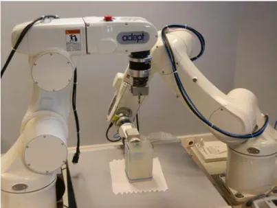
• The Viper s650 and Viper s850 from Omron Adept Technologies, Inc. (Pleasanton, California, United States) are 6 axis industrial manipu-lators, depicted in Fig. 1.5a. The robots communicate with the work-station through a FireWire (IEEE 1394) connection. They were used to hold and actuate the needle or to hold the 3D ultrasound (US) probe. They were also used to apply motions to the phantom in order to simulate patient motions.
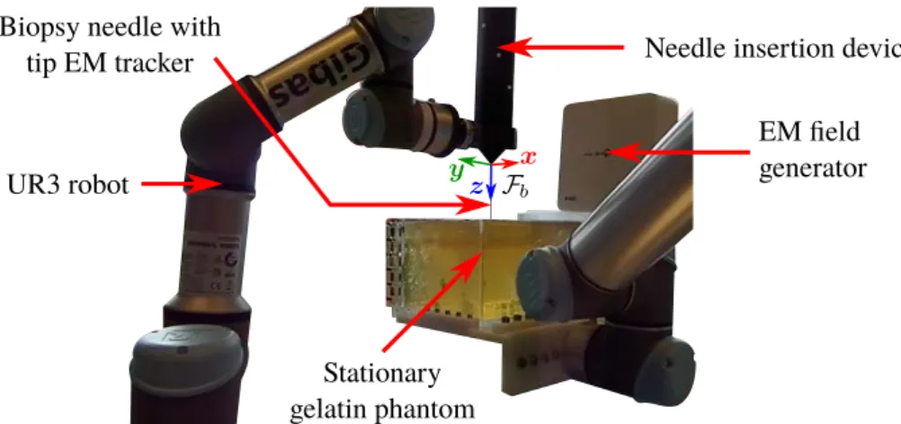
• The UR3 and UR5 from Universal Robots A/S (Odense, Denmark) are 6 axis table-top robots, depicted in Fig. 1.5b. Both robots were connected to a secondary workstation and communicated through Eth-ernet using Robot Operating System (ROS) (Open Source Robotics Foundation, Mountain View, USA). UR3 was used to hold and ac-tuate an insertion device described in the following. UR5 is a larger version of UR3 and was used to apply a motion to the phantom. We also used a 2 degrees of freedom needle insertion device (NID), visible in Fig. 1.5b, designed at the Surgical Robotics Laboratory [SHOM15], which controls the insertion and rotation of the needle along and around its axis. A Raspberry Pi 2 B (Raspberry Pi foun-dation, Caldecote, United Kingdom) along with a Gertbot motor con-troller board (Fen logic limited, Cambridge, United Kingdom) were used to control the robot through pulse-width-modulation (PWM). Motor encoders were used to measure the position and rotation of the needle, allowing to know its effective length that can bend outside the NID. The NID was connected to the end effector of the UR3 through a plastic link, as can be seen in Fig. 1.5b, allowing the control of the 3D pose of the NID with the UR3.
1.5. EXPERIMENTAL CONTEXT
(a) Viper s650 on the left and Viper s850 on the right
(b) UR5 holding a gelatin phantom on the foreground and needle insertion device attached to the UR3 on the background
Figure 1.5: Pictures of the robotic systems used for the experiments: (a) sys-tem used in France and (b) syssys-tem used in the Netherlands.
1.5.2 Visual feedback systems
We used two different modalities to provide a visual feedback on the needle and phantom position. Cameras were used for the evaluation of the perfor-mances of the control framework and ultrasound (US) probes were used to validate the framework using a clinical modality.
We used in France two Point Grey FL2-03S2C cameras from FLIR In-tegrated Imaging Solutions Inc. (formerly Point Grey Research, Richmond, BC, Canada), which are color cameras providing 648 x 488 images with a frame rate up to 80 images per second. Each camera was coupled with a DF6HA-1B lens from Fujifilm (Tokyo, Japon), which has a 6 mm focal length with manual focus. The cameras send the acquired images to the workstation through a FireWire (IEEE 1394) connection. This system was used only with translucent gelatin phantoms to enable the observation of the needle for validation purposes. Both cameras and a gelatin phantom can be seen in Fig. 1.6. A white screen monitor or a piece of paper were used to offer a uniform background behind the phantom that facilitates the segmentation of the needle in the images.
Two different US systems were used for the experiments. For the ex-periments performed in France, we used a 4DC7-3/40 convex 4D US probe (see Fig. 1.7a) from BK Ultrasound (previously Ultrasonix Medical Corpora-tion, Canada), which is a wobbling probe with frequency range from 3 MHz to 7 MHz, transducer radius of 39.8 mm and motor radius of 27.25 mm. This probe was used with a SonixTOUCH research US scanner from BK Ultrasound (see Fig. 1.7b). The station allows an access to raw data via an Ethernet connection, such as radio frequency data or pre-scan B-mode data. For the experiments performed in the Netherlands, we used a 7CF2 Con-vex Volume 4D/3D probe (see Fig. 1.7c) from Siemens AG (Erlangen, Ger-many), which is a wobbling probe with frequency range from 2 MHz to 7 Mhz,
Figure 1.6: Picture of the stereo camera system and one gelatin phantom used for the experiments.
1.5. EXPERIMENTAL CONTEXT (a) BK Ultrasound 4DC7 3D probe (b) BK Ultrasound SonixTOUCH station (c) Siemens 7CF2 3D probe (d) Siemens Acuson s2000 station
Figure 1.7: Picture of the ultrasound components used for the experiments. transducer radius of 44.86 mm and motor radius of 14.84 mm. This probe was used with an Acuson S2000 US scanner from Siemens (see Fig. 1.7d). This station does not give access to raw data nor online access to trans-formed data. Pre-scan 3D US volumes can be retrieved offline using the digital imaging and communications in medicine (DICOM) format. Never-theless, 2D images were acquired online using a USB frame grabber device from Epiphan Video (Ottawa, Ontario, Canada) connected to the video out-put of the station.
1.5.3 Phantoms
Different phantoms were used for the experiments. Porcine gelatin was used in all phantoms, either alone or while embedding ex-vivo biological tissues. We used either porcine or bovine liver as biological tissues. The gelatin and tissues were embedded in transparent plastic containers of different sizes. Various artificial targets were also embedded in some phantoms, in the form of raisins or play-dough spheres of different sizes, ranging from 4 mm to 8 mm.
1.5.4 Workstations
All software developments were made using the C++ language. We used the ViSP library [MSC05] as a basis for the majority of the control frame-work, image processing, graphics user interface and communications. CUDA library was used for optimization of the post-scan conversion of 3D ultra-sound volumes with a Nvidia GPU. Eigen library was used for fast matrix inversion for the needle modeling.
For the experiments performed in France we used a workstation running Ubuntu 14.04 LTS 64-bit and equipped with 32 GB memory, a Intel R
E5-2620 v2@2.10GHz × 6 CPU and a NVIDIA R Quadro R K2000 GPU. For the experiments performed in the Netherlands we used a personal computer running Fedora 24 64-bit and equipped with 16GB memory and a Intel R CoreTM i7-4600U@2.10 Ghz × 4 CPU.
1.5.5 Needles
We summarize the characteristics of the different needles used in the exper-iments in Table 1.1. A picture of the needle used in France and a zoom on the beveled tip can be seen in Fig. 1.8.
1.5.6 Force sensor
For the experiments performed in the Netherlands, we used a Nano 43 force torque sensor from ATI Industrial Automation (Apex, USA), which is a six-axis sensor measuring forces and torques in all 3 Cartesian directions with a resolution of 1.95 mN for forces and 25 µN.m for torques. The sensor was placed between the UR3 robot and the needle insertion device to measure the interaction efforts exerted at the base of the needle, as depicted in Fig. 1.9a.
Table 1.1: Characteristics of the needles used in the experiments. The lengths are calculated from the base of the needle holder to the needle tip.
Needle type Chiba biopsy needle Chiba biopsy stylet Reference Angiotech MCN2208 Aurora Needle 610062
Young’s modulus 200 GPa 200 GPa
Outer diameter 22G (0.7 mm) 23.5G (0.55 mm)
Inner diameter 0.48 mm 0.5 mm
Length (cm) 12.6 from 0.8 to 10.8
Tip type Chiba Chiba
Tip angle 25◦ 25◦
(a) Needle with needle holder (b) Zoom on the needle tip
1.6. THESIS OUTLINE
(a) ATI force/torque sensor (b) Aurora tracker
(c) Aurora field generator
Figure 1.9: Picture of the electromagnetic tracking system and force sensor used for the experiments.
1.5.7 Electromagnetic tracker
For the experiments performed in the Netherlands, we used an Aurora v3 electromagnetic (EM) tracking system from Northern Digital Inc. (Waterloo, Canada), which consists in a 5 degrees of freedom EM sensor (see Fig. 1.9b) placed in the tip of the needle and an EM field generator (see Fig. 1.9c). The system is used to measure the 3D position and axis alignment of the needle tip, with an position accuracy of 0.7 mm and an orientation accuracy of 0.20◦, at a maximum rate of 65 measures per second.
1.6
Thesis outline
In this chapter we presented the clinical and scientific context of this thesis. We defined our general objective as being the robotic insertion of a flexible needle in soft tissues under ultrasound (US) guidance and we described the associated challenges. A list of the equipments used in the various experi-ments presented in this thesis was also provided.
The remaining of this manuscript is organized as follows.
Chapter 2: We present an overview of needle-tissue interaction models. A review of different families of models is first provided, with a classification of the models depending on their complexity and intended use for pre-operative or intra-operative purposes. We then propose a first contribution on the 3D modeling of a beveled-tip needle interacting with soft tissues consisting of two numerical models that can be used for real-time applications and offering the possibility to consider the case of moving tissues. The performances of both models are evaluated and compared through experiments.
Chapter 3: We address the issue of tracking the body of a curved needle in 3D US volumes. The general principles of the acquisition process of US images and volumes are first described. Then we present an overview of
recent detection and tracking algorithms used to localize the whole needle body or only the needle tip in 2D or 3D US sequences. We then propose a new contribution to 3D needle tracking that exploits the natural artifacts appearing around the needle in US volumes. Finally we also propose a method to update our needle model using the measures acquired during the insertion to take into account lateral tissue motions. The updated model is used to predict the new position of the needle and to improve needle tracking in the next acquired US volume.
Chapter 4: We focus on the core topic of this thesis which is the robotic steering of a flexible needle in soft tissues under visual guidance. We first provide a review of current work on flexible needle steering, from the low level control of the needle trajectory to the planning of this trajectory. We then present the main contribution of this thesis, which consists in a needle steer-ing framework that has the particularity to include several steersteer-ing strategies and which is independent of the robotic manipulator used to steer the needle. The performances of the framework are illustrated through several ex-vivo experimental scenarios using cameras and 3D US probes as visual feedback. Chapter 5: We consider the issue of patient motions during the needle insertion procedure. An overview of motion compensation techniques during needle insertion is first presented. We further extend our steering framework proposed in chapter 4 and we exploit the model update method proposed in chapter 3 in order to handle needle steering under lateral motions of the tis-sues. We provide experimental results obtained by using the proposed frame-work to perform needle insertion in a moving soft tissue phantom. These experiments were performed using several information feedback modalities, such as a force sensor, an electromagnetic tracker as well as 2D US.
Conclusion: Finally we provide the conclusion of this dissertation and present perspectives for possible extensions and applications.
Chapter 2
Needle insertion modeling
This chapter provides an overview of needle-tissue interaction models. The modeling of the behavior of a needle interacting with soft tissues is useful for many aspects of needle insertion procedures. First it can be used to predict the trajectory of the needle tip, before inserting the real needle. This can be of great help to the clinicians in order to find an adequate insertion entry point that optimizes the chances of reaching a targeted region inside the body, while reducing the risks of damaging other sensitive regions. Secondly, using thinner needles allows decreasing the patient pain and the risk of bleeding [GP07]. However, the stiffness of a thin needle is greatly reduced and causes its shaft to bend during the insertion. This makes the interaction between the needle and tissues more complex to comprehend by the clinicians, since the position of the needle tip is not directly known from the position and orientation of the base, contrary to rigid needles. The introduction of a robotic manipulator holding the needle and controlling its trajectory can be of great help to unburden the operator of the needle manipulation task. This removes a potential source of human error and leaves the clinicians free to focus on other aspects of the procedure [APM07]. Needle-tissue interaction models are a necessity for the usage of such robotic systems, in order to know how they should be controlled to modify the needle trajectory in the desired way.
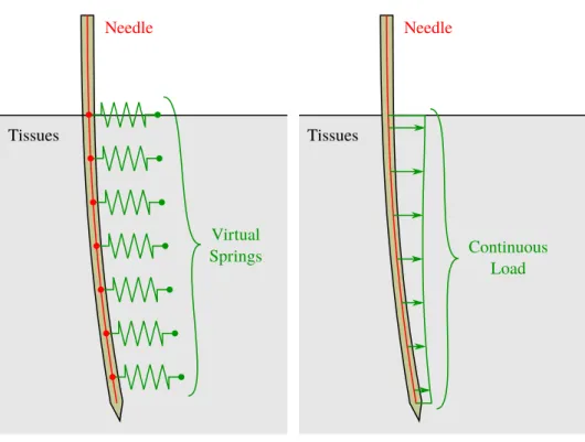
In the following, we first provide a review of needle-tissue interaction models. We address the case of kinematic models (section 2.1), which only consider the trajectory of the tip of the needle, and the case of finite element modeling (section 2.2) that can completely model the behavior of the nee-dle and the surrounding tissues. Then we present mechanics-based models (section 2.3) used to represent the body of the needle without modeling all the surrounding tissues. We further extend on this topic and propose two new 3D models of a needle locally interacting with soft tissues (section 2.4). Finally, in section 2.5 we compare the trajectories of the needle tip obtained with both models to the trajectories obtained during the insertion of a real
needle. The work done using both models was published in two articles presented in international conferences [CKB16a] [CKB16b].
2.1
Kinematic modeling
During the insertion of a needle, a force is applied to the tissues by the needle tip to cut a path in the direction of the insertion. In return the tissues apply reaction forces to the needle tip and the direction of this forces depends on the geometry of the tip, as illustrated in Fig. 2.1.
In the case of a symmetric needle tip, the lateral forces tends to negate each other, leaving only a force aligned with the needle. The needle tip trajectory then follows a straight line when the needle in inserted. However when the needle tip has an asymmetric shape, as for example in the case of a beveled or pre-curved tip, inserting the needle results in a lateral reaction force. The needle trajectory bends in the direction of the reaction force. The exact shape of the trajectory depends on the properties of the needle and tissues. The stiffness of the needle introduces internal forces that naturally act against the bending of the shaft. The deformations of the tissues also creates forces all along the needle body, which modify its whole shape.
Kinematic modeling is used under the assumption that the tissues are stationary and no lateral motion is applied to the needle base, such that the different forces are directly related to the amount of deflection observed at the tip. The value of all these forces are ignored in this case and only the trajectory of the tip is represented from a geometric point of view. The whole needle shaft is ignored as well and the insertion and rotation along and around the needle axis are assumed to be directly transmitted to the tip. This way the modeling is limited to the motion of the tip during the insertion or rotation of the needle. Note that this kind of representation is limited to asymmetric geometries of the tip, since a symmetric tip would only produce a straight trajectory that does not require a particular modeling.
Kinematic modeling of the behavior of a needle during its insertion was
Figure 2.1: Illustration of the reaction forces applied to the needle tip by the tissues depending on the tip geometry. A symmetric tip, on the right, induces symmetric reaction forces. An asymmetric tip, on the left, induces asymmetric reaction forces which can modify the tip trajectory.
2.1. KINEMATIC MODELING
(a) Unicycle model (b) Bicycle model
Figure 2.2: Illustration of the 2D unicycle and bicycle models associated with an asymmetric tip needle inserted in soft tissues. Models are overlaid on a beveled tip needle (top) and on a pre-curved tip needle (bottom). Blue and red arrows represent the translation and rotation of the wheels, respectively. Note that the two wheels on the bicycle model are fixed with respect to each other, such that a rotation motion is naturally created during the translation if φ 6= 0, contrary to the unicycle model for which the rotation has to be added artificially.
first proposed by Webster et al. [WIKC+06] using the two non-holonomic
models of unicycle and bicycle.
Unicycle model: The 2D unicycle consists in modeling the tip as the center of a single wheel that can translate in one direction and rotate along another normal direction, as illustrated in Fig. 2.2a. During the needle insertion, the needle tip is assumed to follow a circular trajectory. The ratio between the translation and rotation is fixed by the natural curvature Knat of this circular trajectory and depends on the needle and tissue properties such that
˙x = vins cos(θ)
˙y = vins sin(θ)
˙θ = Knatvins,
(2.1)
where x and y are the coordinates of the wheel center, i.e. the needle tip, θ is the orientation of the wheel and vins is the insertion velocity.
Bicycle bicycle: The 2D bicycle model uses two rigidly fixed wheels at a distance Lw from each other, such that the front wheel lies on the axis of the rear wheel and is misaligned by an fixed angle φ, as illustrated in Fig. 2.2b. The point representing the needle tip lies somewhere between the two wheels, at a distance Ltfrom the rear wheel. In addition to the rotation and the velocity in the insertion direction observed with the unicycle model, the tip is also subject to a lateral translation velocity, directly linked to the