HAL Id: hal-03048814
https://hal.archives-ouvertes.fr/hal-03048814
Submitted on 9 Dec 2020
HAL is a multi-disciplinary open access
archive for the deposit and dissemination of
sci-entific research documents, whether they are
pub-lished or not. The documents may come from
teaching and research institutions in France or
abroad, or from public or private research centers.
L’archive ouverte pluridisciplinaire HAL, est
destinée au dépôt et à la diffusion de documents
scientifiques de niveau recherche, publiés ou non,
émanant des établissements d’enseignement et de
recherche français ou étrangers, des laboratoires
publics ou privés.
Binson Babu, Patrice Simon, Andrea Balducci
To cite this version:
Binson Babu, Patrice Simon, Andrea Balducci.
Fast Charging Materials for High Power
Applications.
Advanced Energy Materials, Wiley-VCH Verlag, 2020, 10 (29), pp.2001128.
Any correspondence concerning this service should be sent
to the repository administrator:
[email protected]
This is a
publisher’s version published in:
https://oatao.univ-toulouse.fr/27021
To cite this version:
Babu, Binson and Simon, Patrice and Balducci, Andrea Fast
Charging Materials for High Power Applications. (2020) Advanced
Energy Materials, 10 (29). 2001128. ISSN 1614-6832
Official URL :
www.advenergymat.d
Fast Charging Materials for High Power Applications
Binson Babu, Patrice Simon, and Andrea Balducci*
DOI: 10.1002/aenm.202001128
in the near future, especially in the trans-portation field.[3] Figure 1 is showing a com-parison of the characteristics of high power lithium-ion batteries (LIBs), supercapaci-tors (SC), and hybrid-ion capacisupercapaci-tors (HICs), which are the devices of choice for high power applications.[4–6] All these devices are commercially available, and it is fore-seen that their market will strong increase in the future.[7–9] Among them, high power LIBs, which rely on chemical storage are the systems displaying the higher energy density, but also the lower cycle life. SC, which relay on physical storage, are dis-playing high power and extremely high cycle life, but limited energy density. The energy, power, and cycle life of HIC, which rely on both physical and chemical storage, lie in between those of LIB and SC.[10,11] Although commercially available, the performance and the safety of high power LIB, SC, and HIC need to be strongly improved in order to match the requirements of all future applications. To realize such an improvement, the selection and the realization of advanced electrode (and electrolyte) materials is essential. These materials should be low cost, ecofriendly, re-usable, and natu-rally abundant. Furthermore, they should display high reversible capacity and long cycling stability, which is extremely important for high power application.[12] The aim of this review paper is to supply an overview about the electrode materials utilized nowadays in high power devices and, at the same time, to iden-tify the most suitable candidates for the realization of the next generation of advanced devices.
1.1. Classification of Electrode Materials
Taking into account the mechanism of energy storage, the electrode materials can be classified into three types: faradaic, pseudocapacitive, and non-faradaic (capacitive) (Figure 2).[13]
In faradaic materials redox reactions are taking place on the bulk electrode. These reactions involve ions, for example, lithium ions in LIB, of the bulk electrolyte, which can be inserted/extracted from host (electrode) structure, or they can lead to reversible conversion reaction and/or alloying for-mation. As a result of the faradaic process the host materials undergo phase transformations, which provides a sharp peak in the cyclic voltammetry and a flat plateau during galvanostatic charge–discharge experiments (Figure 2d,g).[14–17]
Pseudocapacitive materials are also storing charge thorough faradaic reactions. In these materials, however, the reactions are non-diffusion limited (for instance, taking place on the electrode surface) and they do not lead to crystallographic phase change in the material itself (Figure 2b). Due to this
An overview of fast charging materials for high power applications is given. The behavior at high current density of several anodic and cathodic materials that have been utilized in lithium-, sodium-, and potassium-ion batteries is considered. Furthermore, the behavior of capacitive and pseudocapacitive materials suitable for electrochemical capacitors and, also, of those that have been utilized for the realization of hybrid-ion capacitors, which are nowadays an interesting reality in the field of high power devices, is discussed. The advantages and limitations of all these materials are critically analyzed with the aim of understanding their impact on real devices. On the basis of this analysis, the most important aspects are identified, which should be addressed in the future for the realization of advanced high power devices.
Dr. B. Babu, Prof. A. Balducci
Institute for Technical Chemistry and Environmental Chemistry Center for Energy and Environmental Chemistry Jena (CEEC Jena) Friedrich-Schiller-University Jena
Philosophenweg 7a, Jena 07743, Germany E-mail: [email protected] Prof. P. Simon
Centre Interuniversitaire de Recherche et d’Ingénierie des Matériaux (CIRIMAT)
Joint Research Units (UMR) Centre national de la recherche scientifique (CNRS)
Université Paul Sabatier
118 route de Narbonne, Toulouse Cedex 9 31062, France Prof. P. Simon
Réseau sur le Stockage Electrochimique de l'Energie (RS2E) FR CNRS 3459
Amiens Cedex 80039, France
The ORCID identification number(s) for the author(s) of this article can be found under https://doi.org/10.1002/aenm.202001128.
1. Introduction
Rising concerns over the environmental pollution and the increasing use of alternative energy sources is urgently calling for the development of green and sustainable electrochemical energy storage devices.[1,2] In the future, it will be necessary to develop a large number of different devices, each of them suited for specific applications. Among them, those suitable for high power application, in which a fast deliver of energy (in the order of minutes or less) is required are presently considered of great importance. These devices are already used in a large number of applications, ranging from portable devices to safety systems, and it has been foreseen that their use will increase significantly
10th Anniversary Article
© 2020 The Authors. Published by WILEY-VCH Verlag GmbH & Co. KGaA, Weinheim. This is an open access article under the terms of the Creative Commons Attribution License, which permits use, distribution and repro-duction in any medium, provided the original work is properly cited.
(quasi-2D). The underpotential deposition pseudo capacitance occurs due to the (monolayer) adsorption of ions at the elec-trode surface above their redox potential, whereas in redox pseudocapacitance the faradaic charge transfer induced adsorp-tion of ions onto the surface of the material, causing continuous changes in the oxidation state of the active material.[24] Interca-lation pseudocapacitance involves the fast intercaInterca-lation of ions into the crystal structure of the active host material resulting in faradaic charge transfer with no crystallographic phase change. Although the processes described above are rather different, the electrochemical response they are generating is very similar. This situation resulted in an open vivid discussion on the scientific communities working on these materials. In this respect, the work of Brousse et al.[19] as well as of Dunn[25] appears extremely helpful to understand the differences between these materials.
The non-faradaic (capacitive) materials are storing energy through a physical process based on a reversible formation of an electric double layer at the electrode/electrolyte interface. Here, the oxidation state of the materials remains unchanged. This process is extremely fast, and the devices utilizing it are typically indicated as electrical double layer capacitors (EDLCs). Due to the limited amount of charge stored through this process, EDLCs display significantly lower energy than LIB. On the other hand, the power and the cycle life of these latter are much lower than the one of the former. The electrochemical signature of non-faradaic material consists of a triangular charge–discharge profile and a rectangular voltammogram (Figure 2f,i).[25]
The charge stored in faradaic materials is typically reported in terms of specific charge capacity (mAh g−1). In the case of non-faradaic materials the specific or gravimetric capacitance (F g−1 or F cm−3) is mainly utilized. It is important to note that in the case of pseudocapacitive materials this latter value might be misleading, as reported in several works.[19] Providing capacity values, for example, expressed in C g−1, would be helpful even with materials that show a clear capacitive signature.[26]
1.2. Electrochemical Signature of High Power Materials
The different charge storage mechanisms existing between the classes of materials discussed above leads to significant differences in their kinetic behavior, which can be analyzed qualitatively as well as quantitatively by using various electro-chemical techniques: i) cyclic voltammetry (CV), ii) galvano-static charge–discharge (GC), iii) electrochemical impedance spectroscopy, etc. As illustrated above in Figure 2, the differen-tiation between faradic and capacitive type of materials appears
rather straightforward. On the contrary, differentiating between the faradaic materials and pseudocapacitive materials is more complex, since both undergo redox process, but their electro-chemical signature might be very similar to that of capacitive materials. For example, pseudocapacitive materials like hydrous RuO2, MnO2, T-Nb2O5, are displaying voltammetric profiles very similar to that of capacitive materials although their charge process is implying a (continuous) change of their oxidation state. In the last years several studies have been dedicated to
Schiller-University, Jena. His research mainly focuses on the development and characterization of novel electrolytes and electrode materials for high power hybrid ion capaci-tors and metal-ion batteries.
Patrice Simon is currently a distinguished professor of materials sciences at Université Paul Sabatier (Toulouse, France) and serves as deputy director of the French network on electro-chemical energy storage (RS2E). His research activities are focused on the modifica-tion of material/electrolyte interfaces in electrodes for electrochemical energy storage devices, including batteries and electrochemical capacitors.
Andrea Balducci is professor of applied electrochemistry at the Institute for Technical Chemistry and Environmental Chemistry and at the Center for Energy and Environmental Chemistry Jena (CEEC Jena) of the Friedrich-Schiller University Jena, Germany. He is working on the development and characteri-zation of novel electrolytes and active/inactive materials suitable for the realization of safe and high performance electrical capacitors, metal-ion batteries, and polymeric batteries.
the analysis of the behavior of these materials with the aim of differentiating the diffusion controlled from the non-diffusion controlled (surface controlled) processes.[18,27,28]
The level of the reversibility of an electrochemical reac-tions can be defined based on the voltage difference of the anodic and cathodic redox potential peak (ΔEa,c) in the cyclic voltammogram and the voltage shift of the peaks with respect
to the variation of sweep rate (υ). It has been widely reported that for diffusion limited bulk faradaic processes, an increase in ΔEa,c at increased sweep rate (υ) is observed, while in pseudocapacitive materials the ΔEa,c is small and varies only a little over a wide range of sweep rate. As a consequence, the (bulk) faradaic materials shows a significant ΔEa,c even at low sweep rates, whereas the pseudocapacitive materials shows
Figure 2. Schematic illustration of the electrode processes taking place at a) faradaic, b) pseudocapacitive, and c) capacitive materials. (a–c) Reproduced
with permission.[13] Copyright 2019, John Wiley and Sons. The figure also reports a schematic representation of a typical galvanostatic charge–discharge
and cyclic voltammogram of faradaic d,g) pseudocapacitive, e,h) capacitive, and f,i) materials, respectively.
Figure 1. Ragone plot (left) and table (right) comparing the electrochemical properties of Li-ion battery (LIB), supercapacitor (SC), and hybrid ion
nism. The kinetics of the charge storage mechanisms can be qualitatively determined from the experimental b-values. The b-value might be helpful to gain indications about the diffusion and non-diffusion controlled processes (which have theoretical b-values of 0.5 and 1, respectively) taking place on faradaic, pseudocapacitive, and capacitive materials.[18,30,33,34] Neverthe-less, it is important to remark that while considering this value it is necessary to carefully take into account the properties, for example, surface area, of the investigated material in order to avoid analysis which are not physically meaningful.
Potentiostatic intermittent titration technique including step potential electrochemical spectroscopy[35] and multiple-step chronoamperometry[36] have been also utilized to determine the contribution of different charge storage mechanisms, and their use is becoming more and more common to investigate these aspects.
2. Materials for High Power Applications:
An Overview
All three classes of material discussed above are utilized for the realization of high power devices. In the following, each of these classes will be considered with the aim of understanding their impact on the behavior and performance of metal-ion bat-teries, supercapacitors, and HIC.
2.1. Materials for Metal-Ion Batteries
The reactions taking place in faradaic materials suitable for rechargeable battery can be divided in three main types: a) insertion/extraction reactions, b) alloy reactions, and c) con-version reactions. Alloy reactions typically lead to huge volume expansion, which might cause cracking of the electrodes and rapid capacity declining. On the other hand, conversion reac-tions typically display large voltage hysteresis in the charge– discharge, which results in a poor efficiency. Because of these limitations, the use of these two classes of materials in high power applications does not appear particularly advanta-geous.[37,38] In this work we will therefore considered only mate-rials relying on insertion/extraction reactions.
The key requirements for the successful implementation of an intercalation material (anode and cathode) in a high power rechargeable battery are:[39,40] i) high ionic and electronic conductivity, which are necessary to guarantee a fast charge– discharge process and ii) highly reversibility and minimal or
to notice that although the working principle of LIB, sodium-ion batteries (NIB), and potassium-ion batteries (KIB) is the same, the materials suitable for high power applications, due to the dif-ferent properties of these ions, might be significantly difdif-ferent. 2.1.1. Lithium-Ion Batteries
LIBs are presently the devices of choice for a large number of applications, ranging from portable devices to electric vehi-cles. Although the realization of high energy LIBs is required for several applications, it can be considered as the main focus of large part of the research dedicated to these devices, also the realization of high power systems appears to be of impor-tance. For this reason, in the last years several efforts have been dedicated to the development of materials able to improve the power density of LIBs.[47]
Anodic Materials for LIBs: Carbon is the cheapest and most abundant element in nature,[48] and carbonaceous materials are extensively utilized in energy storage devices, for example, as negative electrode for commercial LIBs.
Carbonaceous materials can be categorized into three types: graphite/graphitized materials, non-graphitizable hard carbon, and graphitizable soft carbon (Figure 4).
The intercalation process of lithium in these materials can be generally described as[49,50]
↔x ++xe−+
x n n
Li C Li C (2)
Graphite is one of the stable allotropes of carbon, and is showing reversible Li intercalation at a potential close to that of Li-metal (≈0.2 V vs Li/Li+). Yazami discovered the usage of graphite as anode material for LIB,[51] and it was introduced in commercial devices by Sony Inc. in 1991. Since then, due to their low working potential, high reversible capacity and cycling stability, graphite electrode are the state-of-the-art anode of this technology.[52] Graphite is the sequential arrange-ment of graphene layers separated by a distance of 3.35 Å, and bonded by van der Waals forces in ABABA stacking, in which each graphene layers have a honeycomb structure of hexagonal arrangement of carbon atoms.[52,53] The electrochemical activity in graphite happens due to the insertion of Li ion between the graphene layers in 2D manner, and the intercalation occurs through four stages explained by Daumas–Herold model. The theoretical capacity of graphite is ≈372 mAh g−1.[53–56] In order to utilize graphite in LIBs, the formation of a passivation layer
permeable to lithium ions (solid–electrolyte interface, SEI) on
the surface of the graphite electrode is required.[12,57–59] The formation of the SEI implied an irreversible consumption of lithium ions from the electrolytes and cathodes during the initial cycle of the battery, which causes a reduction of the capacity and an increase of the resistance (and thus imped-ance) within the cell.[60–63] Besides, during fast charging lithium electroplating might occur on the SEI layer. This latter process might create dendrite formation over the cycling, which can eventually destroy the cell, and it might reduce the performance of the materials under high current densi-ties.[64,65] Several strategies have been adopted by researchers to improve the electrochemical performances and the rate capa-bilities of graphite electrodes by changing the loading, coating thickness, and porosity,[66,67] modifying the graphite structures and dimensions like ultra-layered graphite,[68] highly graphitic carbon nanosheets (HGCNS), etc.[69] These materials are able to deliver large capacity at rate higher than 10 C.
Amorphous carbons (hard and soft carbons) have been also investigated as negative electrodes for high performance LIBs. The insertion/de-insertion profile of amorphous carbon are different compared to the graphite (Figure 4). In contrast to graphite voltage profile, the hard carbon and soft carbon under-goes a sloping nature which will decrease the cell voltage and hence limits the energy density. Hard carbons can be seen as a
Figure 3. a) Comparison of some properties of interest in view of the application in batteries of Li, Na, and K; each axis’ values are rescaling
inde-pendently. b) Number of publications dedicated to lithium, sodium, and potassium batteries; data from Web of Science (February 2020) by searching “metal ion battery” for each battery chemistry (Li, Na, and K).
Figure 4. Comparison of the voltage profiles of graphite, hard carbon,
and soft carbon. Reproduced with permission.[49] Copyright 2001, John
disordered collection of small graphitic grains, which originate in the presence of nanovoids within the material. Due to these latter, hard carbon based electrodes display a reduced volu-metric expansion than graphite and, furthermore, these defects provides high gravimetric capacity, which is higher than the theoretical capacity of graphite (372 mAh g−1).[43,53,70] However, the high fraction of edge sites present in these materials is influencing the SEI formation, reducing the initial columbic efficiency (due to a large voltage hysteresis), and it is increasing the irreversible capacity loss in full cell device. For these rea-sons, the use of hard carbon appears less attractive in commer-cial devices than that of graphite. The graphitizable soft carbon, in contrast to the non-graphitizable hard carbon, is showing higher electronic conductivity, whose interlayer distance and graphitization degrees can be tuned by thermal treatment.[50,71] However, as in the case of hard carbon, these materials dis-play an initial irreversible capacity much higher than that of graphite. Graphitizable petroleum coke (PeC), mesocarbon microbeads, ex-mesophase and vapor-grown carbon fibers, etc., are typical soft carbons used for Li-ion insertion.[72]
Graphite appears to be the most suitable material for the realization of high energy LIBs. Nevertheless, it has to be noted that for high power application this might not always be the case. As a matter of fact, while in graphite the lithium insertion is hindered every time a new intercalation stage is reached, in soft (and hard) carbon the lithium insertion process does not show significant decrease over the used potential. It has been shown that this difference, which is caused by the different structural and microstructural properties of these carbonaceous materials, has important consequences on the capacity reten-tion of these carbons during the high rates, for example, those typically used in lithium-ion capacitors (LIC). Under these circumstances the use of soft carbon (and also hard carbon) might become more favorable (Figure 5).[73]
In order to improve the electrochemical performances of LIBs in terms of rate capabilities, cycle life, etc., also different types of carbon based materials have been developed and con-sidered.[68,69,74–86] Dubal et al.[80] synthesized nitrogen-doped carbon nanopipes (N-CNPipes) for high power Li-ion inser-tion anode material. The kinetic studies of material shows high anodic and cathodic b-values and a capacitive contribution of 93.1% at a high scan rate of 10 mV s−1, which is attributed to
the pseudocapacitive nature due to the surface redox reactions between Li-ions and N-functional groups on the surface of N-CNPipes and the disordered carbon structure due to defects induced on the graphene layers.
Titanium based materials have been intensively investigated as alternative to conventional carbon based anodes. The interest on these materials is related to their limited volume strain (<4%) during the lithium insertion/extraction process, which is ensuring a very high reversibility, and thus cycling stability for the devices in which they are used. Furthermore, since the lithium insertion/extraction is taking place at a potential above 1.0 V versus Li/Li+, the use of these classes of materials avoids lithium dendrites, ensuring high safety.[87–89]
TiO2 is one of the most abundant, environmentally friendly, and low cost available material, and it shows very interesting electrochemical properties.[90]
The general insertion/extraction reaction of lithium ions in TiO2 can be expressed as:
↔x ++x −+ x
TiO2 Li e Li TiO2 (3)
where x depends on the morphology, crystallographic orienta-tion, and the different polymorphs of TiO2.[87] The reversible accommodation of 1 mole of lithium in TiO2 crystal structure gives a high theoretical capacity of ≈335 mAh g−1. Even though many polymorphs are reported, only anatase, rutile, brookite, and bronze phases have been investigated for LIB applications. Among them, anatase and bronze (TiO2 (B)) appears as the most promising for high power applications and for this reason they will be considered in the following.
Anatase is the most thermodynamically stable form of TiO2 polymorphs. It has tetragonal body-centered space group with two TiO6 octahedra sharing two adjacent edges with other two similar TiO6 octahedra.[91–93] The lithium ion insertion in the anatase framework results in the for-mation of Li-rich and Li-poor phases, where Li hopping between the two octahedral interstitial sites can take place. The lithium ion diffusion has been estimated in the range of ≈10−17 cm2 s−1.[32,94] It has been shown that the use of nanosized anatase TiO2 particles is leading to an improve-ment of capacity and to a change of the storage process, in which a solid solution reaction is more prominent than
Figure 5. a) GITT measurements of graphite and soft carbon based anodes during lithiation and b) C-rate test of graphite and soft carbon based anodes
the two-phase equilibrium reaction typically of not nano-sized materials.[95] This behavior has been well described by Wagemaker et al.[96] which utilizing neutron diffraction could show the particle size dependence of anatase to the Li composition. Dunn et al.[27] revealed the pseudocapaci-tive behavior of nanosized TiO2 anatase. They investigated in detail the variation of b-value of TiO2 nanocrystals at different potentials and they showed that the low b-value (0.55) at 1.70 V versus Li/Li+ can be associated with fara-daic current, while the high b-value (0.8–1.0) at higher and lower peak potentials indicates the occurrence of non-dif-fusion-limited processes of capacitive current. They were able to differentiate the capacitive and faradaic contribu-tions in TiO2 nanocrystals having different thicknesses, and they show that an increase of the capacitive contribution is taking place when the particle size is decreasing (Figure 6). As a consequence, the nanosized anatase TiO2 is displaying improved behavior during test carried out at high current density, making these nanomaterials appealing for high power applications.
TiO2 (B) is another interesting TiO2 polymorph, which dis-plays properties similar to anatase, but with the advantage of a reduced irreversible capacity during cycling.[41,97,98] Marchand and co-workers discovered TiO2 (B) in 1980, showing that this polymorph features an open perovskite-like layered crystal structure and low density compared to other polymorphs.[88] It has been shown that the lithium insertion process in TiO2 (B) is taking place through a two-phase reaction,[99] and Zukalova and co-workers[100] investigated the pseudocapacitive behavior of this material.
As in the case of anatase, the use of nanosized TiO2 (B) par-ticles, which are shortening the lithium diffusion path ways on the material, is favorable in view of high power applications. Armstrong et al.[101,102] synthesized TiO2 (B) nanowires with diameters in the range of 40–60 nm and lengths up to several micrometers. They showed that these materials display high capacity (305 mA h g−1) and excellent capacity retention over prolonged cycling. The same group has also synthesized TiO2 (B) nanotubes, showing that these materials display high spe-cific capacity (338 mAh g−1) and they are able to deliver very
Figure 6. a) Galvanostatic discharge curves for nanocrystalline TiO2 films at a rate of ≈1 C for films at different dimensions, b) b-values for the 10 nm
film plotted as a function of potential for cathodic sweeps (Li+ insertion). Inset: power law dependence of current on sweep rate (at 1.60 V, b = 1.0, and
at 1.70 V, b = 0.55), c) cyclic voltammetry (0.5 mV s−1) showing the capacitive contribution for the three TiO
2 films, and d) the histogram compares the
quantitatively differentiated lithium intercalation and capacitive contributions for TiO2 nanoparticle films at sweep rate of 0.5 mV s−1. Reproduced with
good capacity also at high current densities (95 mAh g−1 at 2000 mA g−1, corresponding to 21 C).[103]
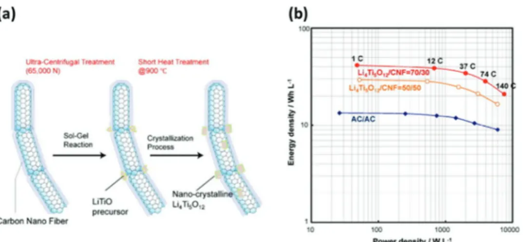
The spinel framework materials described by the general for-mula AB2O4, provides robust crystalline structure with 3D diffu-sion pathways, and for these favorable features they have been largely investigated as electrode materials for energy storage devices. The spinel structure (Li4Ti5O12) (LTO), undergoes a reversible two-phase reaction from spinel (Li4Ti5O12) to rock salt structure (Li7Ti5O12) by reducing Ti4+ to Ti3+, that is resulting in a theoretical capacity of 175 mAh g−1. The volume change associated to this reversible reaction, which take place at 1.55 V versus Li/ Li+, is extremely low (≈0.2%), and for this reason LTO is con-sidered a “zero strain” anodic material.[104] Due to these positive features, its low cost and environmental friendliness, LTO is con-sidered as one of the most promising anodic material for practical application.[105] One of main drawback of LTO is its insulating nature. For this reason, in the last years tremendous efforts have been made to enhance the electronic mobility and the ionic diffu-sion of this material, with the goal to realize LTO based electrodes able to display high performance.[106–115] Kim et al.[112] devel-oped LTO nanowires able to deliver high capacity at low C-rate (165 mAh g−1 at a 0.1 C) and, at the same time, to retain large part of this capacity (>90%) also at high C-rate . In 2009 Naoi et, al.,[113] developed a high rate LTO based electrode featuring a unique nanostructure in which nanocrystalline LTO (≈5–20 nm) were grafted onto carbon nanofiber anchors (nc-Li4Ti5O12/CNF). This innovative material was obtained utilizing a sol–gel synthesis under ultra-centrifugal force (Figure 7). The group showed that nc-Li4Ti5O12/CNF can deliver a very high capacity at very high C-rate (158 mAh g−1 at 300 C, which corresponds to 95% of the capacity delivered by the electrode at 1 C-rate).
TiNb2O7 (TNO) is a mixture of titanium-niobium based binary metal oxides, which was proposed by John B. Good-enough's group as an alternative anode material for Li-ion bat-tery.[116] The theoretical capacity of TNO is 388 mAh g−1 (which results from a 5-electron transfer reaction involving the redox couples Ti4+/Ti3+, Nb5+/Nb4+, and Nb4+/Nb3+) and the lithium-ion insertlithium-ion within its structure is taking place at a potential higher than 1 V versus Li/Li+. These properties, together with
its 2D structure, are making TNO an attractive alternative to lithium titanate.[34,117,118] As other titanates, TNO displays intrinsic poor electronic and ionic conductivities, which are limiting its use in high power applications.[116] In the last years many efforts have been dedicated toward the realization of designed TNO, for example, nanostructures,[119–125] micro-spheres,[123,126] nanospheres,[127] nanofibers,[128] carbon com-posites,[129–132] doping with hetero atoms.[133,134] Guo et al.[135] reported about the use of nanoporous TNO synthesized via a sol–gel synthesis, showing that this material was able to deliver a stable capacity of 128 mAh g−1 at 50 C. Song et al.[134] pro-posed the use of TNO doped with Mo6+ ions (Mo-TNO), and they showed that these materials exhibit high capacity at high C-rate (184 mAh g−1 at 100 C). Utilizing TNO nanospheres, Cheng et al.[127] realized systems displaying high capacity and high stability (160 mAh g−1 after 10 000 cycles at 5 C).
Table 1 compares some properties of importance for high power applications of selected anodic materials belonging to the families discussed above.
The variation of the specific capacities at different current densities of the materials considered in Table 1 is compared in Figure 8. As shown, the anodic materials of LIBs are able to deliver high specific capacity up to current densities of 10–50 A g−1. Above these values their performance starts to decline quite significantly. To date, graphite still appears as the carbonaceous material able to display the best set of properties for the realization of high power LIBs. Titanium base anodes are also displaying very promising performance at high current densities, but their use might reduce the cell voltage (and thus the energy) of the devices limiting the range of application of LIBs based on these materials.
Cathodic Materials for LIBs: The cathodic materials utilized in commercial LIB consist of transition metal oxides and/or layered compound. In the following session, the high power behavior of some of these compounds will be considered.[15,40,136]
Layered transition metal oxide having a general formula of LiMeO2 (Me = transition metal elements such as Co, Ni, and Mn) have been largely utilized as cathodic materials for LIBs. LiCoO2 (LCO) was proposed by Goodenough and it is the first
Figure 7. a) Schematic illustration for the two-step formation procedure of the nc-Li4Ti5O12/CNF composite, b) Ragone plots of hybrid capacitor
sys-tems ((nc-Li4Ti5O12/CNF)/AC, assembled using two types of the composites with weight ratio of Li4Ti5O12/CNF = 50/50 or 70/30) and conventional
transition metal oxide cathode material which has been suc-cessfully introduced in commercial devices.[137] LCO displays a cubic close-packed arrangement “O3-type structure.”[40,138] It has a theoretical capacity of 274 mAh g−1 and a high volumetric capacity of 1363 mAh cm−3. It features a flat plateau around 3.8 V versus Li/Li+. The major disadvantage of this material is its low thermal stability and its high cost and toxicity, due to the presence of Co, and the fact that its structure is very dependent on the amount lithium ions that are extracted during the charge process. For this reason, only 50% of its theoretical capacity can be safely utilized and its practical capacity is ≈140 mAh g−1.[139–142] Okubo et al.[143] reported about the dependency of the electro-chemical property of LCO on the particle size, showing the disappearance of the typical discharge potential plateau of this material in the case LCO particles with size lower than 10 nm.
It has been shown that nanocrystalline LCO (17 nm) might dis-play high rate capability (retention of 65% of the initial capacity at 100 C).
LiNi0.8Co0.15Al0.05O2 (NCA) is a widely used commercial cathodic material, for example, in Panasonic batteries for Tesla EVs, which shows high discharge capacity and calendar life comparable to that of LCO cathode.[144] In the last years consid-erable efforts have been made to synthesize nanosized mate-rials having different morphologies, for example, microrods (NCA-MRs),[145] yolk–shell NCA microspheres (NCA Ms),[146] hierarchical plates of NCA (HP-NCA),[147] able to display high performance also at high C-rates. The hierarchical NC plates (NCA- HP) synthesized by Wang et al.[147] exhibits a high spe-cific capacity of 207 mAh g−1 (0.1 C-rate ) and maintains a capacity of 124 mAh g−1 even at a higher rate of 10.0 C-rate,
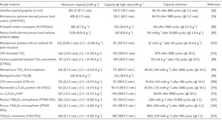
Table 1. Properties of selected high power anodic materials for LIBs.
Anode material Maximum capacity [mAh g−1] Capacity @ high rate/mAh g−1 Capacity retention Reference
Ultrafine layered graphite (2 mm) 395.55 (0.1 C-rate) 139.17 (10 C-rate) 86.2% after 800 cycles (@ 3 C-rate) [68]
Microporous polymer-derived porous hard carbon (CMP-PHC)
408 (0.2 C-rate) 136.2 (60 C-rate) 94.3% after 1800 cycles (@ 5 C-rate) [74]
N-doped carbon nanopipes (N-CNPipes) 982 (0.1 A g−1) 150 (20.0 A g−1) 345 after 1000 cycles (@ 0.5 A g−1) [80]
Peanut shells-derived porous hard carbons (PSDHC-600A)
1230 (0.05 A g−1) 230 (8.0 A g−1) 310 mAhg−1 after 10 000 cycles (@ 5.0 A g−1) [85]
Mesoporous anatase with an ordered 3D pore structure
322 (0.09 C-rate) (1 C = 0.336 A g−1) 85 (107.0 C-rate) 81 mA h g−1 after 50 cycles (@ 36.0 A g−1) [125]
CNT-threaded TiO2 265 (1.0 C-rate) (1 C = 0.170 A g−1) 150 (100.0 C-rate) 87% after 1000 cycles (@ 20 C) [132]
Carbon-supported stacked TiO2 nanosheets (CTNSs)
191 (2.0 C-rate) (1 C = 0.170 A g−1) 109 (50.0 C-rate) 155 mA h g−1 after 150 cycles (@ 10 C) [89] Mesoporous TiO2–B microspheres 256 (0.1 C-rate ) (1 C = 0.335 A g−1) 115 (60.0 C-rate ) 90.0% (149 mAh g−1) after 5000 cycles (@ 10 C) [98]
Nanoparticulate TiO2(B) 230 (0.16 A g−1) 122 (18.0 A g−1) [46]
LTO nanocrystals (LTO-nc) 170 (0.5 C-rate ) (1 C = 0.175 A g−1) 70 (100.0 C-rate ) 95.0% (133 mAh g−1) after 100 cycles (@ 10 C) [106] Nanosized Li4Ti5O12/carbon (N-LTO/C) 161 (0.2 C-rate ) (1 C = 0.175 A g−1) 85.33 (90.0 C-rate ) 95.0% ( 131 mAh g−1) after 1000 cycles (@ 10 C) [115]
nc- Li4Ti5O12/CNF 167 (1.0 C-rate ) (1 C = 0.175 A g−1) 158 (300.0 C-rate ) 90.0% after 9000 cycles (@ 20 C) [113]
Porous TiNb2O7 nanospheres (PTNO NSs) 285 (1.0 C-rate ) (1 C = 0.387 A g−1) 167 (50.0 C-rate ) (160 mAh g−1) after 10 000 cycles (@ 5 C) [127] Porous TiNb2O7 microspheres (PTNO
MSs)
265 (0.1 C-rate ) (1 C = 0.387 A g−1) 143 (100.0 C-rate ) 90% (190 mAh g−1) after 1000 cycles (@ 5 C) [126] TiNb2O7 nanotubes (TNO NTs) 294 (0.1 C-rate ) (1 C = 0.387 A g−1) 180 (100.0 C-rate ) 80% (170 mAh g−1) after 700 cycles (@ 1 C) [123]
Figure 8. Comparison of a) rate capability at different current densities and b) achieved specific capacity at maximum current density of different anodic
which is attributed to its microstructure which facilitates the rapid insertion/extraction of lithium ions.
Spinel LiMn2O4 displays several promising features such high thermal stability, low cost, abundance, and environmental friendliness, but it has a lower capacity compared to LCO.[148,149] Lesel et al.[150] investigated nanostructured LMO and showed that these materials are displaying high anodic and cathodic b-values and exhibit a significant capacitive contribution (72% at 1.0 mV s−1) (Figure 9). These Nanoporous LMO can deliver a capacity of ≈44 mAh g−1 at 50 C.
In 1997, Goodenough group proposed the use of phospho-olivine structure LiFePO4 (LFP) as cathode material for LIB. LFP is a cheap, non-toxic, and ecofriendly material displaying excellent thermal stability. LFP has a theoretical capacity of 170 mAh g−1 and a flat charge–discharge plateau around 3.4 V versus Li/Li+. In the last years a large amount of studies have been dedicated to this material, and many efforts have been made to improve its low electronic conductivity (σe < 10−9 S cm−1) as well as the lithium diffusion coefficient (D ≈10−14 cm2 s−1).[138,151–153] Among the various LFP reported in the literature, the nanostructured core–shell LFP/graphitic carbon composite proposed by Naoi et al.[153] appears as one of the most promising materials for high power application as it is able to deliver capacity of 60 mAh g−1 at 100 C (Figure 10).
Monoclinic Li3V2(PO4)3 (LVP) exhibits high energy and power density, thermal stability, high safety, low costs, and a large theoretical specific capacity of 197 mA h g−1 when charged up to 4.8 V versus Li/Li+.[154] It also features a high average operating potential of around 4 V versus Li/Li+ (∼0.6 V higher than that of LFP). LVP has 3D pathways for Li+ insertion/extraction, which facilitate fast migration of the Li+ ions inside its structure.[154,155] However, LVP suffers from intrinsically low electronic conduc-tivity, which limits its high rate performance. Furthermore, the capacity of LVP usually drops rapidly during the process of Li+ insertion/deinsertion due to side reactions between the active material and commonly used organic electrolytes at such a high potential (4.8 V vs Li/Li+). In the last years several efforts have been dedicated to improve the rate performance as well as the stability at high potential of LVP.[154–158] Among the proposed strategies, the use of ionic liquids assisted syn-thesis appears very interesting. Zhang et al.[159] showed that is
possible to use protic ionic liquids (PILs) as soft template and carbon source for the synthesis of carbon-coated LVP nanocrys-tals embedded in a micrometer-sized carbon matrix. LVP/PIL based electrodes exhibit high performance and stable Li+ ion storage performance due to the fast Li+ diffusivity, high elec-tronic conductivity, and favorable nanoarchitecture of the material. Very high specific capacities of 100 mAh g−1 at 100 C in the potential range of 3.0–4.3 V and 120 mAh g−1 at 50 C in the potential range of 3.0–4.8 V were obtained. Furthermore, excellent cycling stability during 10 000 cycles at 50 C (3.0– 4.8 V) could be demonstrated (Figure 11).
Figure 9. a) Plots of log(peak current) versus log(sweep rate) and b) capacitive contributions to the total current for nanoporous LixMn2O4 (1 < x < 2)
at 1 mV s−1. Reproduced with permission.[150] Copyright 2016, ACS Nano.
Figure 10. Plots of discharge capacity versus charge capacity of a half-cell
consisting of Li/1 m LiPF6 EC + DEC/(LFP/graphitic carbon) composite
as a function of C-rate. (Inset below right: Charge–discharge profiles at different charge C-rates from 1 to 480 C. Inset top left: Schematic illustration of the core–shell nanostructure of the LFP/graphitic carbon composite, representing a minute structure consisting of an amorphous outer sphere of an LFP containing Fe3+ defects and an inner sphere of
crystalline LFP.) Reproduced with permission[153] Copyright 2016, Royal
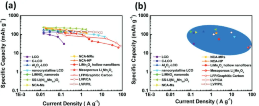
Table 2 compares some properties of importance for high power applications of selected cathodic materials belonging to the families discussed above.[160–163]
The variation of the specific capacities at different current densities of the materials considered in Table 2 is compared in Figure 12. As shown, the cathodic materials of LIBs are able to deliver high specific capacity up to current densities of 50–100 A g−1. Presently, phosphate based cathodes, for example, LFP and LVP, appears as very promising candidates for high power LIBs. The overall high power behavior of high voltage cathodes should be further improved.
2.1.2. Sodium-Ion Batteries
As discussed above, the interest in NIB increased continu-ously in the last years. Sodium is very abundant and cheap, and sodium salts display good solubility in organic solvent.[164,165]
Since metallic sodium and lithium display rather comparable potential plating (ENa+/Na = −2.71 V vs SHE and ELi+/Li = −3.04 V vs SHE), the use of this metal allows the realization of systems having operative voltage comparable to LIBs. Furthermore, since sodium is not forming alloys with aluminum at low potential, its use makes possible the utilization of aluminum current collectors in both, the cathode and the anode. These properties are obviously making NIBs very attractive systems, and nowadays they are considered as one of the most prom-ising alternative to LIBs.[166–169]
Anodic Materials for NIBs: The intercalation process of lithium and sodium ions into graphite is not following a sim-ilar behavior, and the use of this material appears much more challenging for NIB than for LIBs, also in the case of high power applications.[170–172] Theoretical studies indicated that the lim-ited thermodynamic stability of sodium binary graphite interca-lation compounds (b-GICs) is affecting the solubility of Na-ions in graphite, preventing Na intercalation into the graphite.[173–177]
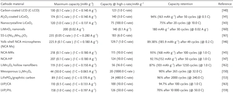
Table 2. Properties of selected high power cathodic materials for LIBs.
Cathode material Maximum capacity [mAh g−1] Capacity @ high c-rate/mAh g−1 Capacity retention Reference
Carbon-coated LCO (C-LCO) 130 (0.1 C-rate ) (1 C = 0.140 A g−1) 123 (1.0 C-rate) [140]
Al2O3-coated LiCoO2 174 (0.1 C-rate ) (1 C = 0.140 A g−1) 140 (3.0 C-rate) 94% (163 mAh g−1) after 50 cycles (@ 0.5 C) [141]
Nanocrystalline LiCoO2 120 (1.0 C-rate ) (1 C = 0.137 A g−1) 75 (100.0 C-rate) 75% after 20 cycles (@ 10.0 C) [143]
LiMnO2 nanorods 200 (0.02 A g−1) 140 (0.1 A g−1) 180 mAh g−1 after 30 cycles (@ 0.02 A g−) [160]
SS-Li(Ni0.5Mn0.5)O2 235 (0.05 C-rate ) (1 C = 0.280 A g−1) 183 (6.0 C-rate) [161]
Yolk–shell NCA microspheres (NCA Ms)
225.9 (0.1 C-rate ) (1 C = 0.180 A g−1) 129.7 (1.0 C-rate) 89.38% (185.9 mAh g−1) after 49 cycles (@ 0.2 C) [146]
NCA-MRs 218 (0.1 C-rate ) (1 C = 0.180 A g−1) 115 (10.0 C-rate) 93% (168 mAh g−1) after 100 cycles (@ 1.0 C) [145]
NCA-HP 207 (0.1 C-rate ) (1 C = 0.180 A g−1) 124 (10.0 C-rate) 92.1%(152 mAh g−1) after 50 cycles (@ 1.0 C) [147]
LiMn2O4 hollow nanofibers 119 (1.0 C-rate ) (1 C = 0.150 A g−1) 56 (16.0 C-rate) 87% (103 mAh g−1) after 1250 cycles (@ 1.0 C) [162]
Mesoporous LixMn2O4 44 (50.0 C-rate) (1 C = 0.065 A g−1) 20 (1000.0 C-rate ) 90% after 265 cycles (@ 32.0 C) [150]
LiFePO4/graphitic carbon 89 (1.0 C-rate) (1 C = 0.170 A g−1) 24 (480.0 C-rate) 96% after 2000 cycles (@ 240.0 C) [153]
LVP/CA 110 (0.5 C-rate) (1 C = 0.133 A g−1) 100 (10.0 C-rate) 94.7% after 100 cycles (@ 1.0 C) [163]
LVP/PIL 158 (1.0 C-rate) (1 C = 0.197 A g−1) 126 (50.0 C-rate) 70% after 10 000 cycles (@ 50.0 C) [159]
Figure 11. a) Cyclic voltammetry of LVP electrodes in the potential range of 3.0–4.8 V versus Li/Li+ at a scan rate of 0.05 mV s−1 and b) specific discharge
capacity of LVP electrodes when charged/discharged at various discharge current densities in the range of 1–50 C (inset shows the SEM image of LVP/ PIL nanoparticles). Reproduced with permission.[159] Copyright 2015, Elsevier.
Yoon et al.[174] systematically investigated the graphite intercala-tion behavior of various alkali metals (AM = Li, Na, K, Rb, Cs) and demonstrated that the instability of Na-GIC is due to the unfavorable local Na–graphene interaction (≈0.5 eV) compared with those for other AMs. This work suggested that an effective strategy to increase the Na-ion accommodation in the graphite host is to screen the Na-ions with solvent molecules in order to mitigate the direct local interactions between the Na-ions and the graphene layers.
Jache et al.[178] reported about an improved Na-ion intercala-tion inside the graphite realized by co-intercalaintercala-tion mechanism involving ether based electrolytes and sodium. They showed that utilizing sodium triflate (NaOTf) in diglyme it is possible to achieve capacities in the order of 100 mAh g−1, which can be main-tained for a high number of charge–discharge cycles. Utilizing a similar approach, Kim et al.[179] reported that graphite electrode can deliver in the electrolyte NaPF6 in diethylene glycol dimethyl ether (DEGDME) capacity of ≈150 mAh g−1 at low current den-sity, which are decreased to more than 75 mAh g−1 at 10 A g−1. Furthermore, they demonstrated the partial pseudocapacitive behavior Na+-solvent co-intercalation in graphite and estimated the capacitive and intercalation contributions of Na storage quantitatively (Figure 13).
By a process of oxidation and partial reduction of graphite, Wen et al.[180] prepared expanded graphite (EG) with a long-range-ordered layered structure having an enlarged interlayer lattice spacing of 4.3 Å able to deliver reversible capacity of 284 mAh g−1 at a current density of 20 mA g−1.
The feasibility of Na-ion intercalation in non-graphitizable hard carbon was first demonstrated by Stevens and Dahn.[171] The hard carbon based electrode display a high capacity of ≈300 mAh g−1 (tenfold that of graphite), but also a low initial coulombic efficiency. Although this low efficiency is a bar-rier for practical utilization, this material in nowadays the anode of choice for commercial NIB.[181,182] There are various models proposed to explain the mechanism of Na storage in hard carbon.[183,184] The first model was the card-house model proposed by Stevens et al.[171] which consider two distinct Na-storage mechanisms. Subsequently, Mitlin's group showed that nanopore filling is not responsible for the dominant Na-ion charge storage mechanism at lower voltage plateau regions[185,186] and Bommier et al.[187] proposed a three-part storage mecha-nism, by utilizing the ex situ XRD, and Na-plating experiments, indicating that the Na-ion intercalation between graphene sheets and minor Na-ion adsorption on pore surfaces are respon-sible for the low voltage plateau region. Later studies based on
Figure 12. Comparison of a) rate capability at different current densities and b) achieved specific capacity at maximum current density of different
cathodic materials for LIB (the marked area is giving a visual indication about the range of capacities and current densities achievable by these materials).
Figure 13. a) Voltage profile (1st and 50th cycle) of graphite in a sodium triflate (NaOTf) diglyme electrolyte. Reproduced with permission.[178] Copyright
2014, John Wiley and Sons. b) Quantitative contributions of capacitive and intercalation of Na-ions in graphite electrode in NaPF6 in DEGDME
binding energies shows the two stages “adsorption-pore-filling sodium storage mechanism” in hard carbons.[188] Various studies showed that the more amorphous nature of non-graphitizable hard carbon (compared to graphite) is favorable also in view of high power application.[189,190] Ding et al.[191] investigated the Na-ion intercalation in air activated peanut shell ordered carbon (PSOC-A), showing that these materials can deliver a capacity of 107 mAh g−1 at a higher current density of 3.2 A g−1 (≈10 C), and retain 75% of their initial capacity after 10 000 cycles. Qie et al.[192] proposed the use of sulfur-doped carbon and showed that these material deliver a capacity of 120 mAh g−1 at 5 A g−1.
Also graphitizable soft carbons have been considered as anodic materials for the SIB anode.[71,193,194] Yao et al.[195] showed the use of microporous soft carbon nanosheets (CNSs) make the reali-zation of electrode able to deliver high capacity (232 mAh g−1 at 20 mA g−1) and high performance at high current densities (103 mAh g−1 at 1.0 A g−1) possible. This high performance is attrib-uted to the extra sodium-ion storage sites and the high kinetics of Na-ions at the micropores, and edge defects in the nanosheets.[44]
Titanium based anodes have been widely investigated also for NIBs. It has been shown that apart from the crystal struc-ture, the electrochemical performance of TiO2 anodes for NIBs is also depending on the textural as well as microstructural fea-tures, stability of SEI, etc.[196–200] As in the case of graphite, the larger size of Na-ions compared to Li-ions is affecting the use of these materials in NIB.[201,202] The electrochemical performance of TiO2 anodes can be enhanced by nanocrystallization, which
shortens the diffusion pathway. Coating and doping also helps to improve its electronic conductivity as well as mechanical stability.[203–205]
Mitlin and co-workers[206] investigated the behavior of mesoporous anatase TiO2 nanocrystals electrodes, showing that these electrodes exhibits a highly stable reversible capacity (≈150 mA h g−1) and good rate capability. Passerini and co-workers[207] showed that in contrast with the pure two phase inter-calation reaction of Li-ions in anatase TiO2, the Na-ions undergo a different reaction mechanism involving the formation of interme-diate sodium titanate phase, and the formation of an amorphous sodium titanate phase able to provide a reversible specific capacity of about 140 mAh g−1. Chen et al.,[208] showed the fast Na+ pseu-docapacitive intercalation behavior of TiO2/graphene nanocom-posites (capacity contribution of 78.2% at a scan rate of 5 mV s−1) and reported that nanostructured black anatase titania can deliver a specific capacity of 208 mAh g−1 at 0.2 C and deliver high capacity also at higher C-rate. Babu et al.[205] made a comparative study of the semicrystalline (BTNT) and crystalline brown TiO2 (DBTNT) nanotubes, aggregates in a flower-like morphology, containing Ti3+ induced by hydrothermal method. The kinetic study reported in this work reveals that the crystalline TiO2 dis-plays higher capacity compared to the brown TiO2 (57% vs 47%) and the former can be utilized as high power anode material (Figure 14).
Yang et al.[209] fabricated nitrogen-doped TiO
2(B) nanorods which exhibit a specific capacity of 225 mA h g−1 , good rate
Figure 14. Comparison of a) powder XRD pattern, b) Raman spectra of BTNT and DBTNT, with commercial pristine white anatase TiO2, capacitive
performance, and a good cycling stability (capacity retention of 93.4% ratio after 200 cycles at 2 C). The open structural frame-work of sodium titanates host matrixes can easily accommodate larger alkali ions without any structural degradation.[210–212] Senguttuvan et al.[213] reported that layered structured Na
2Ti3O7, which can reversibly uptake two Na-ions per formula unit at an average potential of 0.3 V versus Na/Na+, provides a capacity of 200 mAh g−1. Ko et al.[214] reported that the exfoliated Na2Ti3O7 nanoplatelets and nanosheets (Na2Ti3O7 NP-NS) display high capacities in the range of 100–150 mA h g−1 at higher rates and also exhibits a capacitive contribution of 84% at 10 mV s−1. Li et al.[215] developed Na2Ti7O15 nanotubes on a Ti net sub-strate used directly as a binder-free anode for Na-ion batteries, showing that these materials deliver high reversible capacity
(258 mA h g−1 at 50 mA g−1) and exhibit 96% capacity retention over 200 cycles at 1.0 A g−1.
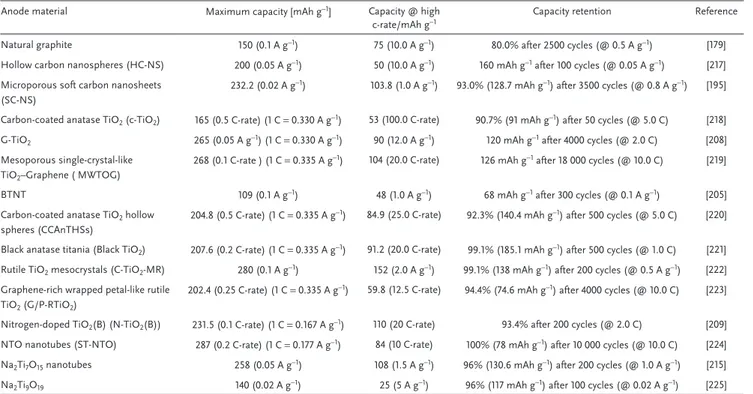
Table 3 compares some properties of importance for high power applications of selected anodic materials belonging to the families discussed above.[216–225]
The variation of the specific capacities at different current densities of the materials considered in Table 3 is compared in Figure 15. As shown, the anodic material of NIBs are able to deliver high specific capacity up to current densities of 10 A g−1. Above these values their performance starts to decline. To date, hard carbon, due to their low cost and higher capacity appears as the most promising carbonaceous anodes. How-ever, their irreversible capacity during the first cycles needs to be decreased in the future. An interesting alternative for high
Figure 15. Comparison of a) rate capability at different current densities and b) achieved specific capacity at maximum current density of different
anodic materials for NIB (the marked area is giving a visual indication about the range of capacities and current densities achievable by these materials).
BTNT 109 (0.1 A g−1) 48 (1.0 A g−1) 68 mAh g−1 after 300 cycles (@ 0.1 A g−1) [205]
Carbon-coated anatase TiO2 hollow spheres (CCAnTHSs)
204.8 (0.5 C-rate) (1 C = 0.335 A g−1) 84.9 (25.0 C-rate) 92.3% (140.4 mAh g−1) after 500 cycles (@ 5.0 C) [220] Black anatase titania (Black TiO2) 207.6 (0.2 C-rate) (1 C = 0.335 A g−1) 91.2 (20.0 C-rate) 99.1% (185.1 mAh g−1) after 500 cycles (@ 1.0 C) [221] Rutile TiO2 mesocrystals (C-TiO2-MR) 280 (0.1 A g−1) 152 (2.0 A g−1) 99.1% (138 mAh g−1) after 200 cycles (@ 0.5 A g−1) [222] Graphene-rich wrapped petal-like rutile
TiO2 (G/P-RTiO2)
202.4 (0.25 C-rate) (1 C = 0.335 A g−1) 59.8 (12.5 C-rate) 94.4% (74.6 mAh g−1) after 4000 cycles (@ 10.0 C) [223]
Nitrogen-doped TiO2(B) (N-TiO2(B)) 231.5 (0.1 C-rate) (1 C = 0.167 A g−1) 110 (20 C-rate) 93.4% after 200 cycles (@ 2.0 C) [209]
NTO nanotubes (ST-NTO) 287 (0.2 C-rate) (1 C = 0.177 A g−1) 84 (10 C-rate) 100% (78 mAh g−1) after 10 000 cycles (@ 10.0 C) [224]
Na2Ti7O15 nanotubes 258 (0.05 A g−1) 108 (1.5 A g−1) 96% (130.6 mAh g−1) after 200 cycles (@ 1.0 A g−1) [215]
power applications are titanium based materials although their use is limiting the cell voltage.
Cathodic Materials for NIBs: The properties of the cathode of NIB are strongly influencing the operative voltage as well as the power output of the devices.[226,227]
Transition metal oxide can be categorized as sodium-free metal oxides MOx (M = V, Mn, Mo) and sodium-inserted metal
oxides (NaxMO2, 0 < x ≤ 1; M = Fe, Mn, Ni, Co, Cr, Ti, V, and
their combinations).[227–229] Vanadium oxide (VO
2) has been long regarded as an interesting cathode for NIBs due to its theoretical capacity (323 mA h g−1) satisfactory capacity, structural flexibility, low cost, and large availability. During the initial Na-insertion process, the VO2 spontaneously changes to the stable NaVO2 phase and then the reversible reaction occurs between Na0.3VO2 and NaVO2 during charging and discharging.[230–232] Vanadium pentoxide (V2O5), which can be divided in orthorhombic and bilayered V2O5, has been also considered as cathodic material for NIBs.[233,234] The electrochemical performance of orthorhombic V2O5 is improved by various processes such as nanoporous carbon encapsulation,[235] by engineering hollow nanoarchi-tecture, etc. Wang's group[236] synthesized V
2O5 hollow nano-spheres, which shows a high specific discharge capacity of ≈150 mA h g−1 corresponding to the formation of NaV
2O5, and maintains a capacity of 112.4 mA h g−1 at a high current density
of 640 mA g−1. It should be noted, however, that Vanadium is expensive and therefore materials based on this element might not be the most suitable for large-scale production (Figure 16).
The sodium-inserted metal oxides (NaxMO2, 0 < x ≤ 1; M = Fe,
Mn, Ni, Co, Cr, Ti, V, and their combinations) can be divided on the basis of their structure in two main types: a) tunnel struc-ture and b) layered strucstruc-ture. These materials have been largely investigated and used in NIBs. Among the various compounds, Na0.44MnO2 that has a theoretical capacity of 121 mA h g−1, is prob-ably the most extensively investigated.[237–239] The 1D ultralong and continuous fibrous network structure of Na0.44MnO2 nanofibers developed by Fu et al.[239] exhibits a superior rate performance with a reversible specific capacity of 69.5 mAh g−1 at 10 C.
The layer structured sodium-inserted metal oxide NaxMO2
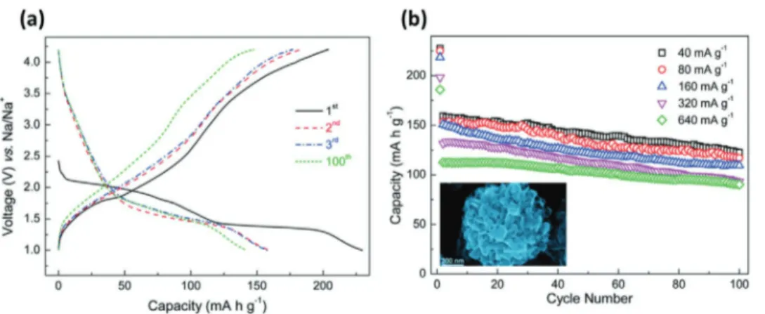
can be categorized into P2 and O3 phases based on the Na envi-ronment and the number of oxygen stacking sequences.[240] The chemical environment of the Na-ions (host sites) at the prismatic and octahedral sites can be represented by “P” and “O,” whereas the numbers “2” and “3” indicate the quantity of repeated transi-tion MeO2-metal layer in a unit cell.[164] The P2-Na0.7CoO2 micro-spheres (s-NCO) developed by Fang et al.[241] exhibits a high spe-cific capacity of 125 mAh g−1 at 5 mA g−1, excellent rate capability of 64 mAh g−1 at a higher rate of 16 C and long-term cycling sta-bility (86% retention in capacity over 300 cycles) (Figure 17).
Figure 17. a) Charge/discharge voltage profiles of the s-NCO electrode at various current rates (inset shows the FESEM image of P2-Na0.7CoO2
micro-spheres). Reproduced with permission.[241] Copyright 2017, John Wiley and Sons. b) Charge and discharge curves at 200 mA g−1 (inset: TEM image) of
NaxFeFe(CN)6 nanocubes (NEF-2). Reproduced with permission.[242] Copyright 2015, Elsevier.
Figure 16. a) Galvanostatic charge–discharge profile of V2O5 hollow nanospheres at a current density of 20 mA g−1 and b) specific capacity versus cycle
Prussian blue analogues (PBAs, NaxM[Fe(CN)6]y·zH2O,
M = Fe, Co, Mn, Ni, Cu, etc.; 0 < x < 2; 0 < y < 1) are a large family of transition metal hexacyanoferrates, and they are attracting an increasing interest as cathode materials for NIBs because of their high theoretical capacity, low cost, and ease of synthesis, as well as because of their (rigid) open framework, rich redox active, and structural stability. The 3D-diffusion channels and the weak interaction with the diffusing ions facilitates the transport of these latter through the material. Liu et al.[242] reported about an Na-rich NaxFeFe(CN)6 nanocubes (NEF-2) able to deliver a capacity of 120 mA h g−1 at a current density of 200 and 74 mA h g−1 when the current density is increased to 1200 mA g−1. One of the main drawback of these materials is their limited thermal stability, which is hindering practical application.[226,229,243–245]
Polyanion-type compounds having robust 3D framework consist of a series of strongly covalently bonded polyanion units (XO4)n− (X = S, P, Si, etc.). Due to their structural stability, high safety, suitable high operating voltages, high thermal-abuse tolerance, and small volume change upon cycling are consid-ered as interesting cathodic materials for NIBs.[227,246–248] Iron, vanadium, and manganese based polyanions are the commonly investigated cathodes for NIBs.
Olivine-type-structured NaMPO4 (M = Fe, Mn) and NASICON-structured NaxM2(PO4)3 (M = V, Ti) are the com-pounds that got greater attention as Na-ion battery cathode materials due to their good electrochemical properties. Zhu et al.[249] reported about carbon-coated triphylite NaFePO4 showing improved electrochemical performance comparable to C-LiFePO4. Several works showed that Na3V2(PO4)3F2 also is a promising cathode for NIBs.[227,247]
Table 4 compares some properties of importance for high power applications of selected cathodic materials belonging to the families discussed above.[250–252]
The variation of the specific capacities at different current densities of the materials considered in Table 4 is compared in Figure 18. As shown, the cathodic materials of NIBs are able to deliver high specific capacity up to current densities which almost reach 50 A g−1. Presently, metal oxides appears more suited for high energy than for high power applications. Olivine-type structure, on the other hand, display a set of properties which make them very promising materials in view of the realization of high power NIBs. PBA also display inter-esting properties, but further investigation is needed to assess the use in real systems.
2.1.3. Potassium-Ion Batteries
As shown in Figure 3, the interest in KIBs increased consid-erably in the last 5 years. Potassium is very abundant, and it displays a low standard reduction potential (EK+/K = −2.93 V vs SHE), which is allowing the realization of high voltage devices. As in the case of NIB, KIB also can be realized uti-lizing Al current collectors for both the cathode and the anode. Furthermore, it has been shown that K based electrolytes might display high conductivities which might be even higher than those of lithium and sodium electrolytes, for example, in the case of imide based salts. These properties are making potas-sium based systems very interesting in view of the realization of high power devices.[253–264]
Anodic Materials for KIBs: A wide variety of carbonaceous materials such as graphite, hard carbon, graphitizable soft carbon, doped carbons, carbon nanotube, have been considered and tested as negative electrodes for KIBs.
The insertion of potassium ions in graphite leads to the formation of KC8, corresponding to a theoretical capacity of
Rod-like Na0.44MnO2 124 (0.10 C-rate) (1 C = 0.120 A g ) 80 (20.0 C-rate) 86% after 500 cycles (@ 20.0 C) [237]
Na0.44MnO2 nanoplates 112 (0.10 C-rate) (1 C = 0.120 A g−1) 96 (10.0 C-rate) 97.8% after 100 cycles (@ 0.5 C) [239]
Na0.44MnO2 nanofibers 128 (0.20 C-rate) (1 C = 0.121 A g−1) 70 (10.0 C-rate) 80 mAh g−1 after 140 cycles (@ 0.42 C) [239]
P2-Na0.7CoO2 microspheres 125 (0.04 C-rate) (1 C = 0.125 A g−1) 64 (16.0 C-rate) 86% after 300 cycles (@ 0.4 C) [241]
Na0.61Fe[Fe(CN)6]0.94·▫0.06 (HQ-NaFe) 170 (0.025 A g−1) 70 (0.600 A g−1) 170 mAh g−1 after 150 cycles (@ 0.025 A g−1) [251]
NaxFeFe(CN)6 nanocubes 120.7 (0.2 A g−1) 73.6 (1.2 A g−1) 87.4 mAh g−1 after 100 cycles (@ 0.2 A g−1) [242]
Na1.72Mn[Fe(CN)6]0.99·2.0H2O (NMHFCs) 117(0.1 C-rate) (1 C = 0.120 A g−1) 45 (40.0 C-rate) 121 mAh g−1 after 30 cycles (@ 0.05 C) [252] Carbon-coated olivine NaFePO4
(C-NaFePO4)
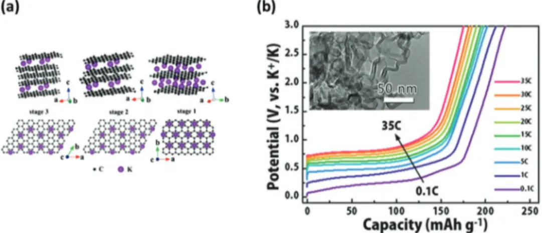
279 mAh g−1 (assuming the full formation of KC8). Some studies indicated that the formation enthalpies of KC8 (−16.5 kJ mol−1) is even more favorable than that of LiC6 (−27.5 kJ mol−1).[265,266] Taking this point into account, the utilization of graphite in KIBs appears certainly less challenging than in NIBs. The potas-sium ion insertion in graphite in non-aqueous electrolyte was first demonstrated by Jian et al.,[259] which showed that graphite has an high reversible capacity of 273 mAh g−1.[257,267,268] More recently Cao et al.[269] showed that an HGCNC displays capacity of 175 mAh g−1 at 35 C and shows promising cyclability (92% capacity retention after 100 cycles) (Figure 19).
Non-graphitizable hard carbon has been also considered as anode material for KIBs. Jian et al.[270] compared the electro-chemical reaction of Na+ and K+ with hard carbon microsphere electrodes derived from sucrose. They showed that, thanks to the higher diffusion coefficient of K ions (compared to that of Na-ions) within its structure, this material is allowing a better high rate performance for KIBs than for NIBs. The same group also investigated hard–soft composite carbon, showing that this composite electrodes display capacity (80 mAh g−1 at 10 C), higher rate capability, and very stable long-term cycling (93% of capacity retention after 200 cycles).[271] Ji's group[259]
investigated the use of soft carbon based electrode, and they showed that the use of this material allows significantly higher performance than graphite at high current density. As illustrate in Figure 20, during test carried out at 5 C the soft carbon elec-trode was able to deliver a capacity of more than 150 mAh g−1, while the graphite electrode was not able to display any signifi-cant capacity.[269,272]
Apart from the carbonaceous materials, potassium titanate (K2Ti4O9, K2Ti6O13, and K2Ti8O17) has been recently investi-gated as anodic materials for KIBs. Kishore et al.[273] reported for the first time the behavior of potassium tetratitanate (K2Ti4O9), synthesized by the solid state method using K2CO3 and TiO2, showing that this material displays an initial capacity of 97 mAh g−1 (theoretical capacity 129 mA h g−1). Dong et al.[274] reported the use of K2Ti6O13 microscaffolds, demon-strating that this material displays excellent rate capability (57 mAh g−1 at 1.0 A g−1). Han et al.,[275] showed that K2Ti8O17 nanorods display a stable capacity exceeding 115 mAh g−1 for 50 cycles.
Table 5 compares some properties of importance for high power applications of selected anodic materials belonging to the families discussed above.[276,277]
Figure 19. a) Structure diagrams of different K-GICs, side view (top row) and top view (bottom row). Reproduced with permission.[259] Copyright 2015,
American Chemical Society. b) Voltage profiles at different depotassiation rates of CNC electrode (inset: HRTEM image of CNC electrode after depotas-siation at the high rate of 35 C). Reproduced with permission.[269] Copyright 2018, John Wiley and Sons.
Figure 18. Comparison of a) rate capability at different current densities and b) achieved specific capacity at maximum current density of different