HAL Id: hal-01023229
https://hal.archives-ouvertes.fr/hal-01023229
Submitted on 11 Jul 2014
HAL is a multi-disciplinary open access
archive for the deposit and dissemination of
sci-entific research documents, whether they are
pub-lished or not. The documents may come from
teaching and research institutions in France or
abroad, or from public or private research centers.
L’archive ouverte pluridisciplinaire HAL, est
destinée au dépôt et à la diffusion de documents
scientifiques de niveau recherche, publiés ou non,
émanant des établissements d’enseignement et de
recherche français ou étrangers, des laboratoires
publics ou privés.
Numerical simulation of arterial dissection during
balloon angioplasty of atherosclerotic coronary arteries
Pierre Badel, Stéphane Avril, Michael Sutton, Susan Lessner
To cite this version:
Pierre Badel, Stéphane Avril, Michael Sutton, Susan Lessner. Numerical simulation of arterial
dissec-tion during balloon angioplasty of atherosclerotic coronary arteries. Journal of Biomechanics, Elsevier,
2014, 47 (4), p. 878-889. �hal-01023229�
Numerical simulation of arterial dissection during balloon angioplasty of atherosclerotic
coronary arteries
Pierre Badel 1, Stéphane Avril 1, Michael A. Sutton 2, and Susan M. Lessner 3
1
Ecole Nationale Supérieure des Mines de Saint-Etienne, CIS-EMSE, CNRS:UMR5307, LGF, F-42023 Saint Etienne, France
2
Department of Mechanical Engineering, University of South Carolina, Columbia, South Carolina 29208, USA
3 Department of Cell Biology and Anatomy, University of South Carolina School of Medicine, Columbia, South
Carolina 29208, USA.
Corresponding author:
Pierre Badel
Center for Health Engineering, Ecole Nationale Supérieure des Mines
158 cours Fauriel, 42023 SAINT-ETIENNE CEDEX 2 France
Phone: +33477420188, Fax: +33477499755
Abstract
Balloon angioplasty is a standard clinical treatment for symptomatic coronary artery disease. In this procedure, controlled damage is applied intraluminally to the wall of a stenotic artery. Dissection of the coronary artery is a commonly observed clinical complication of angioplasty; however, not all dissections can be detected
angioscopically. This work focuses on studying the dissection mechanisms triggered during the early stages of angioplasty in an atherosclerotic coronary artery, addressing the problem by means of a parametric study based on a simplified finite element model and cohesive interface modeling. Our results emphasize the presence of several damage mechanisms, at different locations, that are triggered near the very beginning of the process and evolve competitively, depending on both geometry and material properties of the atherosclerotic vessel. Small-scale damage was evidenced, which would not be detectable by angiography or intravascular ultrasound, but could potentially be sufficient to stimulate smooth muscle cell activation, promoting late-onset complications such as restenosis.
Keywords
Introduction
In advanced atherosclerosis, plaque development can lead to flow-limiting stenosis, resulting in myocardial ischemia accompanied by symptoms such as stable angina. Balloon angioplasty is a standard clinical treatment for symptomatic coronary artery disease. In this procedure, controlled damage is applied intraluminally to the wall of a stenotic artery in order to restore blood flow and to prevent ischemia of the downstream tissue. This induced damaged can take several forms, including irreversible deformation of the tissue caused by overstretch during balloon inflation, plaque fracture, and dissection of the plaque from the underlying vessel wall (Fitzgerald et al. 1992; Honye et al. 1992; Tenaglia 1997). Since arterial wall damage is thought to contribute over the long term to restenosis, leading to eventual re-occlusion of the treated vessel, considerable effort has gone into understanding the mechanisms and consequences of each mode of damage. Computational simulations of arterial damage due to overstretch and inelastic deformation (Balzani et al. 2012; Gasser and Holzapfel 2007a) or to plaque fracture (Ferrara and Pandolfi 2008; Gasser and Holzapfel 2007b) have been reported in the literature.
Dissection of the coronary artery is a commonly observed clinical complication of angioplasty (Honye et al. 1992). Coronary artery dissection can lead to myocardial infarction if the dissected layer partially or totally occludes the vessel lumen, leading to downstream ischemia. Substantial dissections appear as angioscopic filling abnormalities or as overt separation of layers when viewed by intravascular ultrasound (IVUS) (Honye et al. 1992). These may be treated by additional stenting at the time of the original intervention. However, not all dissections can be detected angioscopically. Another type of damage noted clinically is intramural hematoma, or accumulation of blood within the arterial wall, which is most readily identified by IVUS or by intravascular optical coherence tomography (OCT). In one clinical series, a large percentage (86%) of intramural hematomas could be traced to propagation of an intimal tear; however, a smaller number demonstrated no apparent
connection with the lumen by IVUS (Maehara et al. 2002), suggesting that other mechanisms such as damage to the vasa vasorum and subsequent hemorrhage may contribute to their development (Nalbandian and Chason 1965). Arterial dissection or intramural hematoma which is not detected at the time of the original angioplasty can lead to emergent re-occlusion of the treated vessel (Maehara et al. 2002; Tenaglia 1997).
Based on recent experimental work that demonstrated a considerable range of variation in tearing strength of human left anterior descending (LAD) coronary arteries (Wang et al. 2013b), we investigated the question of whether some patients may be more at risk of complications during balloon angioplasty than others, depending on mechanical properties (tearing strength) of the arterial media and intima. These recent experimental data
indicate that critical fracture energy (Gc) is significantly greater for intima than for media in LAD coronaries from patients with non-ischemic cardiomyopathy. We have also shown in mouse models that adhesion strength of plaques depends on plaque composition (Wang et al. 2013a), so it is reasonable to suggest that tearing strength of human coronary artery layers may vary among individuals depending on specific pathology (an obvious example would be connective tissue disorders such as Marfan’s syndrome (Pratt and Curci 2010). Less information is available regarding realistic parameters for Mode II failure, although in some cases this seems to predominate.
Our recent experimental studies have suggested that we re-visit the question of dissection mechanisms during coronary angioplasty. Depending on the respective adhesion or tearing strengths of the arterial constituents in each layer, it is hypothesized in this study that dissection or failure mechanisms may vary during balloon angioplasty. The present paper focuses on the early stages of angioplasty prior to the evolution of inelastic damage in the adjacent, lesion-free wall. The aim is to study what the dissection mechanisms are and especially how they are triggered.
To address this question, our approach entailed a parametric computational study to investigate the relative importance of intimal and medial tearing strength on tissue failure mechanisms in an epicardial coronary artery undergoing balloon angioplasty. We focused our analysis on a simplified model of the LAD coronary since we have experimental data for tearing (dissection) strength of thickened intima and underlying media in terms of critical fracture energy (Gc). A finite element model was developed including cohesive interfaces to describe
possible damage within the arterial wall, both at the plaque-media interface and within the media itself. Various scenarios were tested in which the influence of the geometrical configuration of the plaque within the artery, the mechanical properties of the plaque constituents, and the cohesive zone properties were evaluated.
Materials and methods
We present in this section the FE model that was developed to study how dissection damage may initiate during balloon angioplasty. Briefly, a 2D idealized-geometry model was defined including multiple materials. The constitutive properties were assumed to be hyper-elastic, or elastic in low-interest areas, and isotropic in this plane. Cohesive interfaces were introduced into the mesh to model possible plaque detachment from the media (plaque shoulder fracture or delamination) and/or dissection within the medial layer. Balloon angioplasty was modeled using a displacement-controlled virtual balloon. From this initial construct, a reference model (i.e. a set of reference parameters) was selected and various scenarios were tested by varying parameters to evaluate the
influence of the cohesive properties, and that of the geometric configuration. All the simulations were run in Abaqus/Standard®. Note that a non-patient-specific model was preferred in this work in order not to limit the generality of the results and the phenomena observed.
1. Geometry and mesh
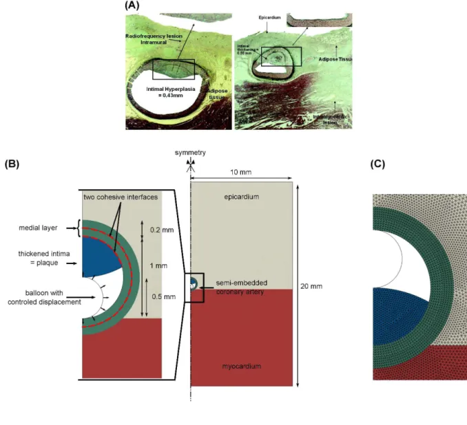
The two-dimensional geometry used in this work was defined based on histological photographs of epicardial coronary arteries as shown in Fig. 1A. The scale of the model was chosen to include the artery itself and its surrounding tissue – myocardium and epicardium – as a semi-infinite domain. A view of the reference geometry of this model is shown in Fig. 1B, where all the dimensions are reported. Note that only one-half of the specimen is actually modeled due to assumed symmetry conditions.
The coronary artery was assumed to consist of a single medial layer containing a partially thickened neointima, i.e., an atherosclerotic plaque. Neglecting the mechanical contribution of the healthy intima is a common and reasonable assumption, since in normal arteries this layer is quite thin and contains relatively little extracellular matrix. Although real arteries consist of three material layers, the intima, media, and adventitia, we have initially chosen to neglect the separate contribution of the adventitia. Instead, we have focused on the initiation and progression of damage in cohesive zones that were incorporated into the model (a) at the plaque-media interface and (b) within the media, to examine whether failure modes may differ depending on the relative resistance to tearing of the two layers. The thickened intimal zone of this artery was modeled as a single homogeneous material for which three geometric configurations were considered. In the reference configuration, the plaque is located on the epicardial side of the vessel wall. In the first alternative configuration, the plaque is located on the myocardial side for the purpose of the sensitivity analysis presented below (see Fig. 1C). The second alternative configuration assumes a concentric plaque with a constant thickness of 0.15 mm. We did not include separate regions for the fibrous cap and lipid core, as seen in thin-cap fibroatheromas (TCFAs)(Virmani et al. 2002), since the lesions being treated by angioplasty are those which cause a critical stenosis; these may be fibrous plaques rather than TCFAs. Previous computational studies have demonstrated that wall stress distributions in lesions having a thick fibrous cap and/or a relatively stiff core are more homogeneous than those in TCFAs (Li et al. 2008; Loree et al. 1992; Versluis et al. 2006).
A specific feature of this model is inclusion of the surrounding tissues: the myocardium in which the artery is semi-embedded and the epicardium, a loose connective tissue. Both are assumed to be perfectly tied to the outer wall of the artery. With this configuration, the boundary conditions on opposite sides of the artery will differ
because the myocardium is much stiffer than the connective tissue/fat on the epicardial side. This difference may contribute to the localization of arterial wall damage during angioplasty.
Lastly, the balloon used for angioplasty was modeled as a thin circular structure whose diameter was increased to perform the angioplasty process. This kind of balloon modeling approach was also previously used by (Gasser and Holzapfel 2007b). In addition, a recent computational study of angioplasty balloon expansion has shown that balloon diameter had a greater impact than balloon internal pressure on the force exerted on the vessel wall (Capelli et al. 2010).
The deformable constituents were meshed with 3-node, plane-strain elements taking into account the pressure as an independent variable. The balloon was modeled using 2-node beam elements. The final mesh is shown in Fig. 1C and includes 26443 elements and 53640 degrees of freedom (mesh density was set based on a preliminary analysis).
2. Constitutive properties
Four different materials were defined and assigned to the different components of the model: thickened intima (or plaque), media, myocardium and epicardium. All components were considered to behave as homogeneous and isotropic materials, and only their passive mechanical response was modeled.
The plaque and medial layer were modeled based on a Neo-Hookean hyper-elastic model. Though simple, this model was deemed sufficient since only the response from physiological to early-angioplasty states is modeled. In addition, in such a cohesive zone problem, the elastic properties of the wall are of secondary importance with respect to the cohesive properties (Merei et al. 2012). The following strain energy function was considered:
( )
-(
-)
= +
W
G
I
K
J 21 3 1
2
2
(1)where
I
1 is the first deviatoric strain invariant (withI
1=
tr
B
,
B
F
F
T•
=
, andF
=
J
−1/3F
) and)
det(
F
J
=
is the volume ratio computed from the gradient tensor F. For infinitesimal deformations, K denotes the bulk modulus (or compressibility modulus) and G denotes the shear modulus. The values of G and K being unknown, they were set within the range of values reported in the literature (Chai et al. 2013; Le Floc'h et al. 2009). They are reported in Table 1.Note that the compressibility parameter of the plaque is of primary importance in this simulation problem. Indeed, atherosclerotic plaques are commonly assumed to be incompressible in the physiological loading range. However in angioplasty, i.e. far beyond this physiological range, the action of the balloon imposes severe plaque deformation, and the plaque may undergo inelastic deformation (Maher et al. 2011) and/or fracture. Modeling these phenomena would require a more complex numerical model and, above all, a method and experiments to identify the associated parameters. The aim of the present study being restrained to the early stages of
angioplasty, it was assumed, as a first approximation in our 2D model, that this phenomenon would be accounted for by the bulk modulus of the plaque. Therefore, we decided to include the compressibility parameter of the plaque in the subsequent sensitivity analysis.
The myocardium and the epicardium were modeled using linear elastic constitutive equations characterized by a Young’s modulus, E, and a Poisson’s ratio, υ. The myocardium stiffness was set in the mid-range of values reported by (Mirsky and Parmley 1973), while the epicardium was assumed to be significantly less stiff. The values of these parameters are listed in Table 1.
3. Cohesive Zone Model
The specific focus of this model was inclusion of two cohesive interfaces to assess the relative potential for damage, detachment or rupture at two locations within the artery. To this aim, cohesive properties – including damage initiation and evolution – were assigned to the edges of elements located between the plaque and the underlying medial layer, and within the medial layer at mid-thickness (see Fig. 1B). The motivation for the choice of a dissection plane at the intima-media boundary arose from reported clinical observations of arterial dissection morphologies visualized by intravascular ultrasound (Honye et al. 1992) as well as reports of intramural hematoma following balloon angioplasty (Maehara et al. 2002).1 The choice of an additional dissection plane within the arterial media (arbitrarily chosen to be midway across the thickness) was based on clinical reports of coronary artery dissection, both spontaneous and iatrogenic, within the media or adjacent to the medial-adventitial boundary (Briguori et al. 2010; Johnson et al. 2012; Shirodaria et al. 2007; Vrints 2010).
The constitutive model associated with these cohesive interfaces was based on a traction-separation response, taking into account the contributions of normal separation (related to mode I fracture) and shear separation
1
Additional cohesive zones may be included in more advanced models, with the selected positions of the CZMs suggested by clinical and/or ex-vivo studies.
(related to mode II fracture). Before damage initiation, the response at these interfaces is linear and characterized by the following equation:
σ
dir =Qdirδ
dir (2)where σdir is the contact stress component in the dir direction and δdir is the separation in dir direction. The
subscript dir denotes either the normal or the tangential direction with respect to the cohesive edge interface definition. Qdir represents a stiffness parameter (unit is MPa/mm) which directly relates the separation in the
cohesive element to the interfacial stress in the neighboring elements on each side of the cohesive edge. The values of parameters Qdir for the reference model of this study are given in Table 2.
Following this linear elastic behavior, damage initiation was defined to model the beginning of degradation in the interface region. Damage begins when the following maximum separation criterion, known as the Damage Initiation Criterion, is met:
max
δ δ
,
δ δ
=
=
n t n t DIC 0 01
(3)where
δ
n0 andδ
t0 are the maximum separation criteria defining the onset of damage in normal or tangential direction in terms of separation. The values of parametersδ
n0 andδ
t0 for the reference model of this study are given in Table 2.Following initiation, damage evolution was described using a scalar damage variable, D, representing the overall damage at each point of the interface. The damage variable, D, monotonically increases from 0 (no damage) to 1 (fracture) and affects the contact stress components according to:
(
)
(
)
if
if
σ σ σ σ σ σ σ = =
−
>
<
−
n n n n n t tD
D
1
0
0
1
(4)where σn and σt are the contact stress components predicted by the elastic traction-separation response (Eq. 2)
without damage. The evolution of the damage variable D was described using an exponential law based on the energy that is dissipated as a result of the damage process (i.e. the fracture energy). The parameters of the
exponential law were automatically fitted by the software providing it with an initial elastic behavior, a damage initiation criterion and critical fracture energies (fracture energy at total fracture, i.e. when D reaches 1). From these data, the damage variable D is computed according to:
f m 0 m n n t t C 0
d
d
D
G
G
δ δσ δ σ δ
+
=
−
∫
(5)where Gc is the critical fracture energy and G0 is the elastic energy at damage initiation as illustrated in Fig. 2.
Here, δm is the so-called effective separation (and
0 m
δ
its value at damage initiation), needed because damage evolves under a combination of normal and tangent separations. This effective separation, δm, is givenby
δ
m=
δ δ
n2+
t2 . Therefore, the input required in this problem is the critical fracture energy. In this study,critical fracture energies available from previous work (Wang et al. 2013b) were used in the reference model, and are reported in Table 2. Note that it was also assumed that the tangent fracture energy (mode II), Gct, was
twice as large as the normal fracture energy (mode I), Gcn. This ratio was maintained constant in all models. In
mixed-mode situations, the software Abaqus® linearly interpolates Gc according to the ratio
t n t
G
m
G +G
=
where Gn and Gt represent the work done by the contact stresses and their conjugate separations in the normal
and tangent directions, respectively, (i.e.
G
c=
G
cnif m = 0 andG
c=
G
ct if m = 1).4. Boundary conditions and sensitivity analysis
Symmetry was first imposed along the vertical centerline of the model (see Fig. 1B). In addition, the only boundary conditions imposed are the displacements of the nodes of the balloon. A radial displacement is imposed to each node from its initial position, di= 0.5 mm, to give a final deformed diameter, df = 1 mm. In the
following, we use inflation progress to denote the variable (d – di)/(df – di) where d is the current diameter of the
balloon. In this form, inflation progress ranges from 0 at the initial state of the model to 1 at its final, fully-inflated, state. Frictionless contact was prescribed between the balloon and the inner wall of the artery.
From the reference configuration of the model described so far, a sensitivity analysis was performed to gain more knowledge of the dissection mechanisms that may be triggered during balloon angioplasty. Two aspects were considered: the geometric configuration of the plaque, and the influence of the constitutive and cohesive properties of the various components. The geometric aspect was addressed simply by comparing the reference
geometric configuration with a configuration in which the plaque is on the opposite side of the wall, i.e. on the myocardial side, and a concentric plaque configuration (plaque covering the entire intimal layer).
The influence of the mechanical response parameters was addressed through different independent scenarios. The first scenario addressed the relative tearing strength of media and adventitia by varying the critical fracture energies Gc of the cohesive interfaces. Independently, the plaque/media Gc and the media/media Gc were scaled
by a factor 1/50 to 50, while keeping Gc twice as large in mode II as in mode I. Similarly, the influence of the
ratio of Gcn to Gct was estimated by running the following simulations. First, both critical fracture energies were
equal, Gct = Gcnref (Gcnref is Gcn at its reference value). Then, from this case, mode II critical fracture energy alone
was varied Gct = 10 × Gcnref, Gct = Gcnref / 10, and mode I critical fracture energy alone was varied, Gcn = 10 ×
Gcnref, Gcn = Gcnref / 10.
Then, the sensitivity to the constitutive parameter K of the plaque, i.e. its compressibility, was addressed by varying K from 15 kPa to 180 kPa. Lastly, the influence of the surrounding tissue was also addressed to evaluate the situation where the artery is partly embedded in the myocardium versus that of the artery being fully
embedded in the loose epicardial tissue. To this aim, the Young’s modulus of the myocardial region of the model was scaled to the same value as that of the epicardial region.
Results
We present in the following section the results of the sensitivity analysis introduced above. For each case, the results extracted from the simulation include:
- The deformed geometries. This result provides qualitative information regarding localization of damage and some hints regarding damage mechanisms.
- For each cohesive interface (plaque/media and media/media), the maps show where the damage initiation criterion, DIC = 1, was reached, and the maximum damage location as well as its value, Dmax.
These results provide the predicted location where dissection initiated and the distribution of damage progress along the edges of the cohesive interfaces.
- For each cohesive interface (plaque/media and media/media), the plots of the maximum value of DIC in the interface, as well as those of δn and δt as a function of the inflation progress (from 0, initial state, to
initiation during balloon inflation. They enable us to distinguish between mode I and mode II evolution, for instance.
1. Reference model
First of all, the main results of the reference model are presented, prior to being compared to the alternative scenarios in the following sections.
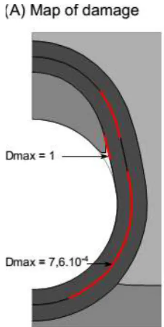
The first visible result is the detachment of the plaque at its shoulder which is obvious from the deformed geometry presented in Fig. 3A. This result is confirmed by the value of the damage variable at the plaque/media interface (Fig. 3B), where a sudden increase up to 1 occurs at 50% of the total balloon inflation, meaning that full detachment is reached. The map of DIC (Fig. 3A) also shows that, at the end of balloon inflation, damage has initiated close to the shoulder of the plaque/media interface, and along almost all the media/media interface, although full separation has not occurred within the media. Plotting the maximum value of the damage initiation criterion DIC (Fig. 3C) during the inflation process shows more specifically that damage is triggered very early in the media, at about 30% inflation, while it is triggered at 50% in the plaque/media interface. The plot of the opening values (Fig. 3D) provides additional information indicating that the detachment of the plaque is mainly due to normal opening (this confirms the visual result) though tangential slip is not negligible. Also, the
media/media interface is subjected to similar values of normal opening and tangential slip until mid-inflation. At this point, the normal opening displacement reaches a maximum followed by a rapid decrease beyond this point, while the tangential slip increases more rapidly and reaches a plateau, so that the normal opening displacement becomes negligible relative to the tangential slip. The rapid decrease in normal displacement beyond mid-inflation is likely due to a much wider contact area between the balloon and the wall at the end of the simulation which tends to close these openings. In addition, we note that the maximum values of D, δn and δt at this
interface are found near the myocardial/epicardial boundary, likely due to the constitutive property heterogeneities in this area that give rise to the development of stress concentrations.
2. Geometric configuration
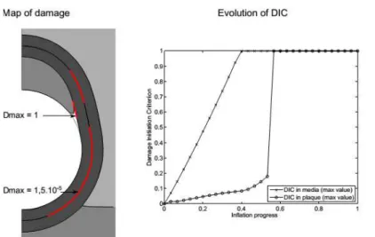
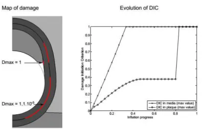
The deformed geometry of the alternative plaque location is shown in Fig. 4A. With respect to the reference, little difference in plaque deformation can be distinguished. More interestingly, in contrast to the reference configuration, DIC = 1 is not observed between the media and the plaque in this configuration, as confirmed by the plot 4B, while dissection is triggered in the media. In addition, in this configuration, the media/media cohesive interface is subjected predominantly to tangential slip rather than to normal opening (Fig. 4C),
increasing the likelihood of mode II failure, while both slip and opening are comparable in the reference configuration.
For the model including a concentric plaque, none of the damage initiation criteria was reached.
3. Critical fracture energies
First, we present here the results of varying the critical fracture energy of the plaque/media interface. Fig. 5 shows the results obtained for the two extreme cases in which Gc of the plaque/media interface is multiplied by
50 and divided by 50. In terms of the deformed geometries, the highest Gc case is very similar to the reference
case, while the lowest Gc case presents a clearly increased plaque shoulder detachment. This visual result is
confirmed by plots of the maximum normal opening at this interface where the value reached at the end of the calculation is much larger for the lowest Gc case (exact value 0.093 mm, out of the scale of the graph). In both
cases, the evolution of opening and slip at the media/media interface present the same trend and similar values.
Next, we examine the effect of varying the critical fracture energy of the media/media interface (results presented in Fig. 6). The most important change evident when looking at the two extreme cases in which Gc of
this interface is multiplied by 50 and divided by 50 is an increase up to 4.1% in the damage variable at the interface for the lowest Gc case (value indicated in 6B). This increase indicates that significant damage is in
progress for this case.
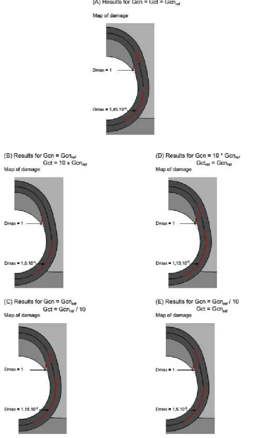
Lastly, we examine the effect of varying the ratio of mode I (Gcn) to mode II (Gct) critical fracture energies
(results presented in Fig. 7). Two types of trends are observed. First, the overall damage value, Dmax, is clearly
dominated by the contribution of mode II in the media-media interface. Indeed, a 10-fold decrease of Gct leads to
714% increase of Dmax (with respect to case Gct = Gcnref), while a 10-fold decrease of Gcn only leads to 10.3%
increase of Dmax (with respect to case Gct = Gcnref). Dmax at the plaque-media interface is not affected.
On the other hand, whether Gct is large or small, there is still the same amount of separation due to mode I
loading at the plaque-vessel interface, and the locations of the damage remain similar at both interfaces. Therefore, it seems that Gct reductions increase the level of damage, but it is still not critical and the plaque is
still separating due to mode I effects.
4. Plaque compressibility
The effect of the plaque compressibility was addressed by varying its bulk modulus K in the range 15-180 kPa. The main results are shown in Fig. 8. For each extreme value, the deformed geometry is noticeably different,
with visible – and obvious – change of volume when K is small. Several changes are also noticeable in the observed damage variables. First, the damage initiation criterion is reached much later in the plaque/media interface when K = 180 kPa (comparing the plots of DIC evolution). Similarly, the plaque is fully detached later in the process of angioplasty, at about 90% of the total inflation, when K = 180 kPa, while it is already detached at 50% inflation when K = 15 kPa (comparing the plots of normal opening). In both cases, the evolution of normal opening and tangential slip at the media/media interface is similar to that of the reference model. On the contrary, these values are much smaller at the plaque/media interface – even zero during most of the inflation – when the plaque is nearly incompressible with K=180 kPa, while they are slightly higher than the reference case in the more compressible case with K = 15 kPa.
5. Surrounding tissue
The result shown here is the extreme case in which the epicardial stiffness value was also assigned to the myocardial region, simulating the case of an artery fully embedded in the loose epicardial tissue (see Fig. 9). Although the final deformed geometry and plaque detachment are very similar in these two cases, the main difference observed in our results affects the media/media interface. In the alternative scenario, the normal opening remains much lower during balloon inflation than it was in the reference model; tangential slip is also slightly lower, and both of these values do not display the peak that is observed in the reference case around mid-inflation. Similarly, the progress of damage is more limited, as D reaches only 5 × 10⁻⁴. These differences are likely due to the fact that partial anchoring of the arterial wall in the myocardium reduces the artery’s deformation in this area, hence inducing mechanical stress concentrations in the vicinity of the myocardium/epicardium interface.
Discussion and future directions
1. Main findings
The model developed in this work focuses on studying the interfacial-cohesion damage mechanisms triggered during the early stages of angioplasty in an atherosclerotic coronary artery, addressing the problem by means of cohesive interface modeling. This work was performed based on a simplified model because the question treated here is not that of patient-specificity. Rather, the objective was to study and understand the possible origin of dissection phenomena during balloon angioplasty which are usually disregarded, in spite of clinical evidence of their occurrence. The general approach presented here was preferred since it may include phenomena that a specific model would not elucidate.
This paper is the starting point toward a comprehensive approach for studying and improving understanding of angioplasty dissection. Several interesting points are raised based on the results of the various simulations presented above. We find two potential mechanisms of damage to the arterial wall that may occur during the early stages of balloon angioplasty. The first of these is the clinically well-documented appearance of plaque detachment at the shoulder region, leading to formation of an intimal flap or partial dissection of the plaque from the underlying media. This mechanism has been elucidated previously in more sophisticated numerical models, for example (Ferrara and Pandolfi 2008; Gasser and Holzapfel 2007a). Clinical complications which could arise from further dissection of an intimal flap, such as re-occlusion of the vessel, are typically pre-empted by
stenting.
Our computational results suggest, moreover, that a second, more subtle form of damage can occur within the arterial media during the early stages of balloon angioplasty, and that the magnitude of this damage depends on the relative tearing or adhesion strength of the plaque and the media. The maps of DIC show that, in almost every one of the simulated cases, damage has initiated along a non-negligible length of the plaque/media interface, and along most of the media/media interface. More precisely, the plots showing the evolution of DIC indicate that damage is triggered in the medial layer early in the inflation process, while damage at the plaque shoulder tends to occur slightly later. These results suggest that the first damage mechanism would be medial dissection within the wall which is triggered by inter-layer normal opening combined with shear slip as indicated by the plots of Figs. 3C, 5, 6 and 8, or even shear slip alone as indicated by the plots of Figs. 4C and 9. This mechanism is hence related to mode II fracture or more generally mixed mode fracture of the underlying biological tissue. Plaque detachment, characterized by a strong normal opening displacement, would actually be the second mechanism, occurring after mid-inflation. This mechanism is clearly related to mode I fracture at the plaque/media interface.
The most striking general trend observed here is that, whatever the configuration (except concentric plaque), damage was always initiated at a very early stage within the medial layer. In addition, when the artery is semi-embedded in the myocardium, the maximum damage always occurred close to the
myocardium/epicardium/media corner. This is probably explained by strong stiffness gradients in this configuration which induce mechanical stress concentrations, in particular medial shear stress.
The results of the sensitivity analysis showed other interesting trends. Damage initiation was found to be
on the myocardial side of the vessel, it was first observed that damage initiation does not occur at the plaque shoulder. Also in this case, as well as in the case of a non-embedded artery, our simulations showed that the damage initiated in the medial layer was mainly related to shear slip within this layer (Fig. 4C and 9). Lastly, the configuration of a concentric plaque did not present any damage initiation, very likely due to the
quasi-cylindrical symmetry which tends to prevent any (normal or tangential) separation from occurring. These results suggest that the damage mechanisms and the risks associated with the balloon-inflation procedure are dependent on the geometric and anatomic configuration of the lesion.
The sensitivity to the tearing strength of the interfaces raises another interesting point. Though the results shown in Figs. 5 and 6 seem to show little difference in the scenarios, it is important to note that the medial dissection damage is sensitive to the critical fracture energy of this interface. This point was highlighted by the maximum damage, Dmax, that was achieved in the low-Gc case with respect to the reference and high-Gc cases. The low-Gc
case, corresponding to a 50-fold decrease of the critical fracture energy, remains clinically sensible and leads to a damage value of 11% while angioplasty is not yet complete in our model. This result demonstrates the likelihood of dissection damage in the medial layer. Studying the relative influence of mode I and mode II fracture energies also highlighted the key role of mode II in medial dissection and that of mode I in plaque detachment. This finding raises questions about the biological consequences of mode I versus mode II damage effects in tissues. This might be an interesting subject for future investigations.
Similarly, the constitutive behavior of the plaque affected the response of the model by either delaying the initiation of plaque shoulder damage or by increasing the effect of this mechanism, while also affecting the level of damage reached in the medial layer.
In summary, by only focusing on the early balloon inflation process, our results emphasize the presence of several dissection damage mechanisms that are triggered near the very beginning of the process and evolve competitively, depending on both geometry and material properties of the atherosclerotic vessel.
2. Relevance of the study and potential clinical implications
Both experimental studies and clinical observations clearly demonstrate the extensive, overt damage to the arterial wall that occurs during balloon angioplasty. In this study, we have focused on the issue of more subtle mechanical damage, particularly slip or separation between tissue planes within the media, which may not be clinically visible during angioplasty. This study revealed that the onset of dissection damage is very early, which is of high importance from the clinical point of view. The use of cohesive interface modeling parameterized by
critical fracture energies demonstrated, indeed, that considering modes of damage other than permanent
deformation is fully relevant. These dissection modes are triggered very early and may not be visible, even when imaging procedures such as IVUS or OCT that readily detect overt dissection and intimal flap formation are performed following the angioplasty. Nevertheless, damage initiation within the media may still have significant local effects at the level of individual smooth muscle cells. The predicted values of maximum opening and tangential slip at the media-media interface are roughly 10-15 micrometers, within the same order of magnitude as the cell size. Overt medial dissection has been associated with smooth muscle cell proliferation in a post-mortem study of patients who died following PTCA (Morimoto et al. 1990) as well as in a rabbit model of restenosis (Dufourcq et al. 1997). The threshold at which SMCs respond to damage or degradation of the surrounding matrix is not well characterized, although it has been reported that SMC interactions with elastin are important at the molecular level for maintenance of a contractile phenotype (Li et al. 1998). Based on these observations, we feel that it is reasonable to suggest that shearing or opening mode damage at the interface of tissue layers in the media may contribute to SMC proliferation and restenosis. This type of small-scale damage would not be detectable by angiography or IVUS, but could potentially alter the mechanical environment of the cells sufficiently to induce biological signal transduction and remodeling or to promote leakage from capillaries of the vasa vasorum in the outer media.
Finally, we would like to suggest that an interesting question for future study pertains to the variation of arterial tearing strength and/or plaque adhesion strength in different patient populations, which has received little attention in the literature. Such variations, if significant, might lead to identification of patient subsets at greater risk of complications such as intramural hematoma or arterial dissection following balloon angioplasty.
3. Limitations of the model
We have focused in this study on addressing a specific question using a simplified computational model of the atherosclerotic coronary artery. A more realistic constitutive model for the plaque would incorporate inelastic behavior to account for the response of the tissue to loading outside the physiological pressure range (for example, (Maher et al., 2011)). Furthermore, structure-based constitutive models which take into account the mechanical response of collagen fibers have been reported for the coronary artery media and could be applied here as well (Hollander et al. 2011; Holzapfel et al. 2005).
The approach based on cohesive interface modeling requires that the location and the direction of possible dissection are pre-defined in the model. This is a major known drawback of this kind of approach. In this
problem, the choice of these locations was guided by clinical knowledge and experience, but more generality could be attained by using other numerical fracture modeling approaches.
The study was restricted to a two-dimensional model. The axial length of plaques is usually limited, which may raise the question of the validity of the plane-strain assumption. Evolution toward a 3D model would enlarge the reach of the present results and possibly help identify new damage initiation mechanisms during angioplasty, for instance due to axial shear.
Acknowledgements
Research reported in this publication was supported by an Institutional Development Award (IDeA) from the National Institute of General Medical Sciences of the National Institutes of Health under grant number P20GM103444, and by the National Science Foundation under grant numbers NSF CMMI-1200358 and EPS-0903795.
Conflict of interest
References Cited
Balzani, D., Brinkhues, S., and Holzapfel, G. A. (2012). "Constitutive framework for the modeling of damage in collagenous soft tissues with application to arterial walls." Computer Methods in Applied Mechanics and
Engineering, 213, 139-151.
Briguori, C., Bellevicine, C., Visconti, G., Focaccio, A., Aprile, V., and Troncone, G. (2010). "In vivo histological assessment of a spontaneous coronary artery dissection." Circulation, 122(10), 1044-6.
Capelli, C., Nordmeyer, J., Schievano, S., Lurz, P., Khambadkone, S., Lattanzio, S., Taylor, A. M., Petrini, L., Migliavacca, F., and Bonhoeffer, P. (2010). "How do angioplasty balloons work: a computational study on balloon expansion forces." EuroIntervention, 6(5), 638-42.
Chai, C. K., Akyildiz, A. C., Speelman, L., Gijsen, F. J., Oomens, C. W., van Sambeek, M. R., van der Lugt, A., and Baaijens, F. P. (2013). "Local axial compressive mechanical properties of human carotid atherosclerotic plaques-characterisation by indentation test and inverse finite element analysis." J Biomech, 46(10), 1759-66.
Dufourcq, P., Louis, H., Dandre, F., Lavie, J., Bonnet, J., and Lamaziere, J. M. (1997). "Phenotypic modification of arterial smooth muscle cells in response to medial dissection." Coron Artery Dis, 8(3-4), 163-70.
Ferrara, A., and Pandolfi, A. (2008). "Numerical modelling of fracture in human arteries." Comput Methods
Biomech Biomed Engin, 11(5), 553-67.
Fitzgerald, P. J., Ports, T. A., and Yock, P. G. (1992). "Contribution of localized calcium deposits to dissection after angioplasty. An observational study using intravascular ultrasound." Circulation, 86(1), 64-70.
Gasser, T. C., and Holzapfel, G. A. (2007a). "Finite element modeling of balloon angioplasty by considering overstretch of remnant non-diseased tissues in lesions." Computational Mechanics, 40(1), 47-60.
Gasser, T. C., and Holzapfel, G. A. (2007b). "Modeling plaque fissuring and dissection during balloon angioplasty intervention." Ann Biomed Eng, 35(5), 711-23.
Hollander, Y., Durban, D., Lu, X., Kassab, G. S., and Lanir, Y. (2011). "Experimentally validated microstructural 3D constitutive model of coronary arterial media." J Biomech Eng, 133(3), 031007.
Holzapfel, G. A., Sommer, G., Gasser, C. T., and Regitnig, P. (2005). "Determination of layer-specific mechanical properties of human coronary arteries with nonatherosclerotic intimal thickening and related constitutive modeling." Am J Physiol Heart Circ Physiol, 289(5), H2048-58.
Honye, J., Mahon, D. J., Jain, A., White, C. J., Ramee, S. R., Wallis, J. B., al-Zarka, A., and Tobis, J. M. (1992). "Morphological effects of coronary balloon angioplasty in vivo assessed by intravascular ultrasound imaging."
Johnson, T. W., Smith, D., Strange, J. W., Bucciarelli-Ducci, C., Lowe, R., and Baumbach, A. (2012). "Spontaneous multivessel coronary intramural hematoma: an insight with OCT." JACC Cardiovasc Imaging, 5(10), 1070-1.
Le Floc'h, S., Ohayon, J., Tracqui, P., Finet, G., Gharib, A. M., Maurice, R. L., Cloutier, G., and Pettigrew, R. I. (2009). "Vulnerable atherosclerotic plaque elasticity reconstruction based on a segmentation-driven optimization procedure using strain measurements: theoretical framework." IEEE Trans Med Imaging, 28(7), 1126-37.
Li, D. Y., Brooke, B., Davis, E. C., Mecham, R. P., Sorensen, L. K., Boak, B. B., Eichwald, E., and Keating, M. T. (1998). "Elastin is an essential determinant of arterial morphogenesis." Nature, 393(6682), 276-80.
Li, Z. Y., Tang, T., J, U. K.-I., Graves, M., Sutcliffe, M., and Gillard, J. H. (2008). "Assessment of carotid plaque vulnerability using structural and geometrical determinants." Circ J, 72(7), 1092-9.
Loree, H. M., Kamm, R. D., Stringfellow, R. G., and Lee, R. T. (1992). "Effects of fibrous cap thickness on peak circumferential stress in model atherosclerotic vessels." Circ Res, 71(4), 850-8.
Maehara, A., Mintz, G. S., Bui, A. B., Castagna, M. T., Walter, O. R., Pappas, C., Pinnow, E. E., Pichard, A. D., Satler, L. F., Waksman, R., Suddath, W. O., Laird, J. R., Jr., Kent, K. M., and Weissman, N. J. (2002).
"Incidence, morphology, angiographic findings, and outcomes of intramural hematomas after percutaneous coronary interventions: an intravascular ultrasound study." Circulation, 105(17), 2037-42.
Maher, E., Creane, A., Sultan, S., Hynes, N., Lally, C., and Kelly, D. J. (2011). "Inelasticity of human carotid atherosclerotic plaque." Ann Biomed Eng, 39(9), 2445-55.
Merei, B., Avril, S., Badel, P., Sutton, M. A., and Lessner, S. M. (2012). "Numerical study of delamination through human aortic media using cohesive elements and two different material laws: Linear elastic and hyperelastic." Biomedical Engineering Society 2012 Annual Meeting, Mira Digital Publishing, Atlanta, GA, USA.
Mirsky, I., and Parmley, W. W. (1973). "Assessment of passive elastic stiffness for isolated heart muscle and the intact heart." Circ Res, 33(2), 233-43.
Morimoto, S., Mizuno, Y., Hiramitsu, S., Yamada, K., Kubo, N., Nomura, M., Yamaguchi, T., Kitazume, H., Kodama, K., Kurogane, H., and et al. (1990). "Restenosis after percutaneous transluminal coronary angioplasty--a histopangioplasty--athologicangioplasty--al study using angioplasty--autopsied heangioplasty--arts." Jpn Circ J, 54(1), 43-56.
Nalbandian, R. M., and Chason, J. L. (1965). "Intramural (Intramedial) Dissecting Hematomas in Normal or Otherwise Unremarkable Coronary Arteries. a "Rare" Cause of Death." Am J Clin Pathol, 43, 348-56.
Pratt, B., and Curci, J. (2010). "Arterial elastic fiber structure. Function and potential roles in acute aortic dissection." J Cardiovasc Surg (Torino), 51(5), 647-56.
Shirodaria, C., Van Gaal, W. J., and Banning, A. P. (2007). "A bleeding kiss: intramural haematoma secondary to balloon angioplasty." Cardiovasc Ultrasound, 5, 21.
Tenaglia, A. N. (1997). "Intravascular ultrasound and balloon percutaneous transluminal coronary angioplasty."
Cardiol Clin, 15(1), 31-8.
Versluis, A., Bank, A. J., and Douglas, W. H. (2006). "Fatigue and plaque rupture in myocardial infarction." J
Biomech, 39(2), 339-47.
Viles-Gonzalez, J. F., de Castro Miranda, R., Scanavacca, M., Sosa, E., and d'Avila, A. (2011). "Acute and chronic effects of epicardial radiofrequency applications delivered on epicardial coronary arteries." Circ
Arrhythm Electrophysiol, 4(4), 526-31.
Virmani, R., Burke, A. P., Kolodgie, F. D., and Farb, A. (2002). "Vulnerable plaque: the pathology of unstable coronary lesions." J Interv Cardiol, 15(6), 439-46.
Vrints, C. J. (2010). "Spontaneous coronary artery dissection." Heart, 96(10), 801-8.
Wang, Y., Johnson, J. A., Fulp, A., Sutton, M. A., and Lessner, S. M. (2013a). "Adhesive strength of
atherosclerotic plaque in a mouse model depends on local collagen content and elastin fragmentation." Journal
of Biomechanics, 46, 716-722.
Wang, Y., Johnson, J. A., Spinale, F. G., Sutton, M. A., and Lessner, S. M. (2013b). "Quantitative measurement of dissection resistance in intimal and medial layers of human coronary arteries." Experimental Mechanics, in press.
List of figures
Figure 1: (A) Histological photograph illustrating the choice of the reference geometry (reprinted with
permission from (Viles-Gonzalez et al. 2011)); (B) Reference model: geometry, dimensions and boundary conditions; (C) Alternative geometry and illustration of the mesh density.
Figure 2: Scheme of principle of the damage evolution model including linear elastic response followed by
exponential softening. Here, G0 is the elastic component of energy and Gc is the total energy.
Figure 3: Results of the reference model: (A) map of the damage variable D ; (B) plot of the damage variable D
at the maximum location in each interface ; (C) evolution of the damage initiation criterion; (D) evolution of the normal opening and tangential slip at each interface during the process. Parameters for this model are the following. At the plaque/media interface, Gc = 0.02 N/mm (mode I) and 0.04 N/mm (mode II); at the
media/media interface, Gc = 0.01 N/mm (mode I) and 0.02 N/mm (mode II); plaque bulk modulus K = 34 kPa.
Figure 4: Results of the model with the alternative geometry: (A) map of the damage variable, D; (B) evolution
of damage initiation criterion; (C) evolution of the normal opening and tangential slip at each interface during the process. Parameters for this model are the following. At the plaque/media interface, Gc = 0.02 N/mm (mode
I) and 0.04 N/mm (mode II); at the media/media interface, Gc = 0.01 N/mm (mode I) and 0.02 N/mm (mode II);
plaque bulk modulus K = 34 kPa.
Figure 5: Results of the sensitivity to the critical fracture energy of the plaque/media interface. (A) Results with
the upper value of Gc and (B) results with the lower value of Gc. Parameters for these models are the following. At the plaque/media interface, (A) Gc = 1 N/mm (mode I) and 2 N/mm (mode II) vs. (B) Gc = 4×10⁻⁴ N/mm
(mode I) and 8×10⁻⁴ (mode II); at the media/media interface, Gc = 0.01 N/mm (mode I) and 0.02 N/mm (mode
II); plaque bulk modulus K = 34 kPa.
Figure 6: Results of the sensitivity to the critical fracture energy of the media/media interface. (A) Results with
the upper value of Gc and (B) results with the lower value of Gc. Parameters for these models are the following. At the plaque/media interface, Gc = 0.02 N/mm (mode I) and 0.04 N/mm (mode II); at the media/media
interface, (A) Gc = 0.5 N/mm (mode I) and 1 N/mm (mode II) vs. (B) Gc = 2×10⁻⁴ N/mm (mode I) and 4×10⁻⁴
Figure 7: Results of the sensitivity to the ratio of mode I to mode II critical fracture energies. Since no change is
observed in terms of opening values and DIC evolution with respect to the reference model, only the map and maximum values of damage are shown.
Figure 8: Results of the sensitivity to the plaque compressibility. (A) Results with the upper value of K and (B)
results with the lower value of K. Parameters for these models are the following. At the plaque/media interface, Gc = 0.02 N/mm (mode I) and 0.04 N/mm (mode II); at the media/media interface, Gc = 0.01 N/mm (mode I) and
0.02 N/mm (mode II); plaque bulk modulus (A) K = 180 kPa vs. (B) K = 15 kPa.
Figure 9: Results for the case of an artery fully embedded in the epicardium. Parameters for this model are the
following. At the plaque/media interface, Gc = 0.02 N/mm (mode I) and 0.04 N/mm (mode II); at the
List of tables
Table 1: Constitutive parameters of the constituents of the coronary artery model (reference parameters).
Table 1: Constitutive parameters of the constituents of the coronary artery model (reference parameters).
Constituent Constitutive model Parameters
Epicardium Linear elastic E = 0.1 kPa , υ = 0.45
Myocardium Linear elastic E = 80 kPa , υ = 0.45
Medial layer Hyper-elastic, Neo-Hookean G = 200 kPa, K = 2 MPa
Atherosclerotic plaque Hyper-elastic, Neo-Hookean G = 20 kPa, K = 34 kPa
Table 2: Parameters of the cohesive interfaces (reference parameters).
Cohesive interface Elastic stiffness parameter Qnormal (MPa/mm) Elastic stiffness parameter Qtangential (MPa/mm) Maximum normal separation criterion
δ
n0 (mm) Maximum tangential separation criterionδ
t0 (mm) Critical fracture energy, Gc (N/mm) Plaque/media 1 1 0.01 0.01 0.02 (mode I) 0.04 (mode II) Media/media 1 1 0.005 0.005 0.01 (mode I) 0.02 (mode II)Figure 1: (A) Histological photograph illustrating the choice of the reference geometry (reprinted with permission from (Viles-Gonzalez et al. 2011)); (B) Reference model: geometry, dimensions and boundary conditions; (C) Alternative geometry and illustration of the mesh density.
Figure 2: Scheme of principle of the damage evolution model including linear elastic response followed by exponential softening. Here, G0 is the elastic component of energy and Gc is the total energy.
Figure 3: Results of the reference model: (A) map of the damage variable D; (B) plot of the damage variable D at the maximum location in each interface; (C) evolution of the damage initiation criterion; (D) evolution of the normal opening and tangential slip at each interface during the process. Parameters for this model are the following. At the plaque/media interface, Gc = 0.02 N/mm (mode I) and 0.04 N/mm (mode II); at the
Figure 4: Results of the model with the alternative geometry: (A) map of the damage variable, D; (B) evolution of damage initiation criterion; (C) evolution of the normal opening and tangential slip at each interface during the process. Parameters for this model are the following. At the plaque/media interface, Gc = 0.02 N/mm (mode
I) and 0.04 N/mm (mode II); at the media/media interface, Gc = 0.01 N/mm (mode I) and 0.02 N/mm (mode II);
Figure 5: Results of the sensitivity to the critical fracture energy of the plaque/media interface. (A) Results with the upper value of Gc and (B) results with the lower value of Gc. Parameters for these models are the following. At the plaque/media interface, (A) Gc = 1 N/mm (mode I) and 2 N/mm (mode II) vs. (B) Gc = 4×10
-4
N/mm (mode I) and 8×10⁻⁴ (mode II); at the media/media interface, Gc = 0.01 N/mm (mode I) and 0.02 N/mm (mode
Figure 6: Results of the sensitivity to the critical fracture energy of the media/media interface. (A) Results with the upper value of Gc and (B) results with the lower value of Gc. Parameters for these models are the following. At the plaque/media interface, Gc = 0.02 N/mm (mode I) and 0.04 N/mm (mode II); at the media/media
interface, (A) Gc = 0.5 N/mm (mode I) and 1 N/mm (mode II) vs. (B) Gc = 2×10⁻⁴ N/mm (mode I) and 4×10⁻⁴
Figure 7: Results of the sensitivity to the ratio of mode I to mode II critical fracture energies. Since no change is observed in terms of opening values and DIC evolution with respect to the reference model, only the map and maximum values of damage are shown.
Figure 8: Results of the sensitivity to the plaque compressibility. (A) Results with the upper value of K and (B) results with the lower value of K. Parameters for these models are the following. At the plaque/media interface, Gc = 0.02 N/mm (mode I) and 0.04 N/mm (mode II); at the media/media interface, Gc = 0.01 N/mm (mode I) and
Figure 9: Results for the case of an artery fully embedded in the epicardium. Parameters for this model are the following. At the plaque/media interface, Gc = 0.02 N/mm (mode I) and 0.04 N/mm (mode II); at the
media/media interface, Gc = 0.01 N/mm (mode I) and 0.02 N/mm (mode II); plaque bulk modulus K = 34 kPa.