HAL Id: tel-02935195
https://tel.archives-ouvertes.fr/tel-02935195
Submitted on 10 Sep 2020
HAL is a multi-disciplinary open access archive for the deposit and dissemination of sci-entific research documents, whether they are pub-lished or not. The documents may come from teaching and research institutions in France or abroad, or from public or private research centers.
L’archive ouverte pluridisciplinaire HAL, est destinée au dépôt et à la diffusion de documents scientifiques de niveau recherche, publiés ou non, émanant des établissements d’enseignement et de recherche français ou étrangers, des laboratoires publics ou privés.
for IoT connectivity in cellular networks
Cesar Augusto Vargas Anamuro
To cite this version:
Cesar Augusto Vargas Anamuro. Opportunity and challenges of Device-to-Device relaying for IoT connectivity in cellular networks. Modeling and Simulation. Ecole nationale supérieure Mines-Télécom Atlantique, 2020. English. �NNT : 2020IMTA0196�. �tel-02935195�
T
HESE DE DOCTORAT DE
L
’É
COLEN
ATIONALES
UPERIEUREM
INES-T
ELECOMA
TLANTIQUEB
RETAGNEP
AYS DE LAL
OIRE-
IMT
A
TLANTIQUE ECOLE DOCTORALE N°601Mathématiques et Sciences et Technologies de l'Information et de la Communication
Spécialité : Informatique
Etude du relayage entre terminaux pour la connectivité des objets
dans les réseaux 5G
Thèse présentée et soutenue à Rennes, le 25/06/2020 Unité de recherche : IRISA
Thèse N° : 2020IMTA0196
Par
Cesar Augusto VARGAS ANAMURO
Rapporteurs avant soutenance :
Philippe Martins Professeur, Télécom Paris Mohamad Assaad Professeur, CentraleSupélec
Composition du Jury :
Président : Martin Heusse Professeur, ENSIMAG, Grenoble Examinateurs : Fabrice Valois Professeur, INSA Lyon
Philippe Martins Professeur, Télécom Paris Mohamad Assaad Professeur, CentraleSupélec
Dir. de thèse : Xavier Lagrange Professeur, IMT Atlantique, Rennes Encadrante : Nadège Varsier Ingénieure Experte, Orange Labs, Meylan
Invité :
Acknowledgements
I address my sincere thanks to my supervisors: Dr. Nadège Varsier and Dr. Jean Schwo-erer, not only for giving me the opportunity to work on this thesis but also for their invaluable support and guidance throughout the development of this research work. I also deeply thank my thesis director, Professor Xavier Lagrange. His knowledge and experience were essential for the development of this research work. I especially appreciate his remarks, recommendations, and rigor during my investigation.
A special thanks to the reviewers: Professor Philippe Martins and Professor Mohamad Assaad for spending time to review my manuscript and for their comments. Also, I would like to express my gratitude to Professor Martin Heusse and Professor Fabrice Valois for being members of the jury in my thesis defense and for their questions and feedback.
I cannot fail to mention my thanks to all the members of the CITY team at Orange Labs Meylan, especially to Juan Carlos for his collaboration in my research. Being part of this research team during the development of my thesis was pleasant and professionally enriching. I also thank the members of the European project ONE5G of which I was a member.
The most important source of emotional support during this time was my family. I am infinitely grateful to my parents Luzmila and Eusebio; my brothers Joel, Jose, and Christian; and my girlfriend Gabriella. They were always by my side despite the thousands of kilometers that separate France and Peru. Finally, I thank my friends and all those people with whom I was able to share pleasant moments throughout these three years in Grenoble.
Abstract
Massive Machine-Type Communication (mMTC) is one of the main services delivered by the fifth Generation (5G) mobile network. mMTC represents a major challenge for 5G network since it is characterized by a large number of low complexity devices that send small data packets. Moreover, mMTC devices are often battery-powered, and the battery is expected to operate for long periods without being recharged or replaced. Traditional cellular networks, which are designed for human communications, are not energy efficient for this type of service. To address this problem, in this thesis, we study the use of Device-to-Device (D2D) relaying as a complementary transmission. In this approach, the mMTC device can transmit its data using a nearby user equipment (UE) as a relay.
First, we calculate the energy consumed in each phase of the communication process for a device located at the cell border that uses Long-Term Evolution for MTC (LTE-M) technology. Then, using a simple model, we compare the energy consumption of cellular and D2D transmission modes, and we determine the optimal relay location. Using stochastic geometry, we analyze the performance of D2D communication with Automatic Repeat reQuest (ARQ) and Hybrid ARQ with Chase Combining (CC-HARQ) with regard to the transmission success probability, the average number of transmissions, and the energy consumption. Finally, we propose an energy-efficient D2D relaying mechanism suitable for mMTC applications thanks to its easy implementation. This mechanism uses a distributed relay selection approach, which prioritizes the selection of the UEs with the best channel qualities. Moreover, we provide an analytical framework to evaluate the performance of our mechanism.
Table of contents
List of figures xiii
List of tables xvii
Nomenclature xix
1 Introduction 1
1.1 Context and Motivations . . . 1
1.2 Contributions . . . 3
1.3 Thesis outline . . . 4
2 Massive Machine-type Communication Overview 7 2.1 Introduction . . . 7
2.2 mMTC 5G Requirements . . . 8
2.3 Cellular Internet of Things . . . 9
2.3.1 LTE-M . . . 10
2.3.2 EC-GSM-IoT . . . 11
2.3.3 NB-IoT . . . 11
2.4 MTC Traffic Model . . . 11
2.4.1 Mobile Autonomous Reporting (MAR) Periodic Reports . . . 12
2.4.2 MAR Exception Reports . . . 12
2.4.3 Network Command . . . 13
2.4.4 Software Update/Reconfiguration . . . 13
2.5 MTC Energy Consumption . . . 13
2.5.1 Energy Consumption Model . . . 13
2.5.2 Energy Consumption Analysis for LTE-M . . . 16
2.5.2.1 MTD Energy Consumption . . . 16
2.5.2.2 LTE-M Battery Lifetime . . . 17
2.5.3.1 Power Saving Mode . . . 21
2.5.3.2 Extended Discontinued Reception . . . 21
2.5.3.3 Energy-Efficient Synchronization . . . 22
2.5.3.4 Signaling Overhead Reduction . . . 22
2.6 Conclusion . . . 23
3 D2D Communications Overview 25 3.1 Introduction . . . 25
3.2 Spectrum Resource for D2D Communication . . . 26
3.3 D2D LTE . . . 27
3.3.1 Architecture . . . 27
3.3.2 Functionalities . . . 28
3.3.2.1 D2D Discovery . . . 28
3.3.2.2 D2D Communication . . . 29
3.3.3 Radio Resource Allocation for Sidelink . . . 29
3.3.3.1 Scheduled Mode . . . 29
3.3.3.2 Autonomous Mode . . . 30
3.4 D2D Relaying . . . 31
3.4.1 D2D Relaying Coverage Scenarios . . . 31
3.4.2 D2D Relaying Phases . . . 31
3.4.2.1 Synchronization Phase . . . 31
3.4.2.2 Discovery Phase . . . 32
3.4.2.3 Data Transmission Phase . . . 34
3.4.3 Relay UE Density Scenarios . . . 34
3.5 Related Studies on D2D Relaying for mMTC . . . 35
3.5.1 Relays Deployed by the Operator . . . 36
3.5.2 UEs as Relays . . . 36
3.6 D2D Relaying Interest for mMTC . . . 37
3.6.1 System Model . . . 37
3.6.2 Energy Consumption Model . . . 38
3.6.3 Minimum-Energy Consumption in D2D Mode . . . 40
3.6.4 Comparison of Energy Consumption in Cellular and D2D Modes . 43 3.6.5 Numerical Results . . . 43
Table of contents ix
4 Performance evaluation of D2D communications with CC-HARQ 49
4.1 Introduction . . . 49
4.1.1 Related Work . . . 50
4.1.2 Key Contributions and Organization . . . 51
4.2 System Model . . . 51
4.2.1 Network Model . . . 51
4.2.2 Propagation Model . . . 52
4.2.3 Retransmission Schemes . . . 53
4.3 Performance Analysis . . . 54
4.3.1 Single Transmission Success Probability . . . 54
4.3.2 Performance of ARQ Scheme . . . 56
4.3.2.1 Global Success Probability for a Given Distance . . . 56
4.3.2.2 Average Number of Transmissions for a Given Distance . 56 4.3.3 Performance of CC-HARQ Scheme . . . 57
4.3.3.1 Global Success Probability for a Given Distance . . . 57
4.3.3.2 Average Number of Transmissions for a Given Distance . 58 4.3.4 Best UE Selected as a Relay . . . 59
4.3.4.1 Performance of ARQ Scheme . . . 59
4.3.4.2 Performance of CC-HARQ Scheme . . . 60
4.3.5 MTD Energy Consumption Modeling . . . 61
4.4 Numerical Results and Discussion . . . 62
4.4.1 Parameters for the Analysis . . . 62
4.4.2 Simulation versus Analytical Results . . . 63
4.4.3 Energy Consumption for a Target Loss Probability of 10% . . . 65
4.4.3.1 Determining the Maximum Number of Transmissions . . 65
4.4.3.2 Energy Consumption Comparison . . . 67
4.5 Conclusion . . . 69
5 Energy-efficient D2D Relaying Mechanism for mMTC Applications 71 5.1 Introduction . . . 71
5.1.1 Related Work . . . 72
5.1.2 Key Contributions and Organization . . . 74
5.2 System Model . . . 75
5.2.1 Network Model . . . 75
5.2.2 Propagation Model . . . 76
5.3 D2D Relaying Protocol Description . . . 77
5.3.2 D2D Relaying Mechanism . . . 77
5.3.3 Random Choice of Time-slot . . . 80
5.3.3.1 Truncated Geometric Random Choice . . . 82
5.3.3.2 Uniform Random Choice . . . 82
5.4 Analytical Model . . . 84
5.4.1 Relay Discovery Probability . . . 84
5.4.1.1 Truncated geometric case . . . 84
5.4.1.2 Uniform Case . . . 85
5.4.2 Number of Slots Used in the Contention Process . . . 86
5.4.2.1 Truncated Geometric Case . . . 86
5.4.2.2 Uniform Case . . . 87
5.4.3 PDF of the MTD-Relay Distance . . . 87
5.4.3.1 Truncated Geometric Case . . . 87
5.4.3.2 Uniform Case . . . 88
5.5 Analysis of the Total Energy Consumption . . . 88
5.5.1 Energy Consumption in Cellular Mode . . . 89
5.5.2 Total Energy Consumption in D2D Mode . . . 90
5.5.2.1 Energy Consumption in the Discovery Phase . . . 91
5.5.2.2 Energy Consumption in the Data Transmission Phase . . 91
5.6 Numerical Results and Discussion . . . 92
5.6.1 Determining the Radius of the Discovery Area . . . 92
5.6.2 Analytical Model Validation . . . 93
5.6.3 Impact of Parameter b . . . 96
5.6.4 Minimization of the Total MTD Energy Consumption . . . 102
5.6.4.1 Optimization in the Uniform Random Choice . . . 102
5.6.4.2 Optimization in the Truncated Geometric Random Choice 104 5.6.5 Comparison of MTD Energy Consumption in Cellular Mode and D2D Mode . . . 106
5.7 Conclusion . . . 110
6 Conclusion and Perspective 111 6.1 Conclusion . . . 111
6.2 Perspective . . . 112
Publications Made during the Thesis 114
Table of contents xi
Appendix A Fundamental Concepts of Stochastic Geometry 125
A.1 Spatial Point Process . . . 125 A.1.1 General Poisson Point Process (PPP) . . . 126 A.1.2 Operations on Poisson Point Processes . . . 127
Appendix B Proof of Equations used in this thesis 129
B.1 Performance of ARQ when the Best UE is Selected as a Relay . . . 129 B.1.1 Transmission Success Probability . . . 129 B.1.2 Average Number of Transmissions . . . 130 B.2 Performance of CC-HARQ when the Best UE is Selected as a Relay . . . . 131 B.2.1 Transmission Success Probability . . . 131 B.2.2 Average Number of Transmissions . . . 132
Appendix C LTE-M Link-Level Simulations 135
C.1 PUSCH . . . 136 C.2 PDSCH . . . 136 C.3 PRACH . . . 138
Appendix D Résumé en français 141
D.1 Contexte de la thèse . . . 141 D.2 Contributions . . . 142
D.3 Comparaison de la consommation d’énergie des modes cellulaire et D2D . 143
D.4 Évaluation des performances d’une communication D2D avec CC-HARQ . 144 D.5 Mécanisme de relayage D2D adapté aux applications IoT . . . 145
List of figures
1.1 Expected growth of massive IoT connections (billion) [1]. . . 2
2.1 CIoT network architecture (based on [2]). . . 10
2.2 CDF of the packet size of uplink reports. . . 14
2.3 MTD operating states. . . 15
2.4 Reporting cycle (based on [3, 4]). . . 15
2.5 Message sequence for LTE-M energy consumption analysis. . . 18
2.6 Cumulative LTE-M energy consumption at 164 dB MCL. . . 19
2.7 PSM and eDRX techniques (based on [5]). . . 21
3.1 D2D communications use cases [6]. . . 26
3.2 Spectrum resource for D2D communication. . . 27
3.3 Simplified D2D architecture (based on [7]). . . 28
3.4 Public safety direct discovery with Model A and Model B [8]. . . 29
3.5 Resource pool for sidelink (based on [9]). . . 30
3.6 Coverage scenarios for D2D relaying. . . 32
3.7 D2D relaying phases. . . 33
3.8 Cell area and inter-site distance. . . 35
3.9 D2D relaying process. . . 38
3.10 Energy consumption in D2D mode versus normalized UE-BS distance, con-sidering BS, UE and MTD aligned. . . 45
3.11 Energy consumption comparison D2D mode versus cellular mode, the BS, the UE, and the MTD are aligned. . . 45
3.12 Total energy consumption depending on the UE location, for dm,b = 800 meters. . . 46
4.1 Network model for D2D autonomous resource allocation. . . 52
4.2 Retransmission scheme. . . 53
4.4 Number of transmissions of ARQ and CC-HARQ as a function of the
modi-fied MTD-relay distance. . . 65
4.5 Average number of transmissions of ARQ and CC-HARQ as a function of the UE density. . . 66
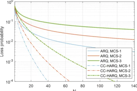
4.6 Loss probability as a function of the maximum number of transmissions. . . 67
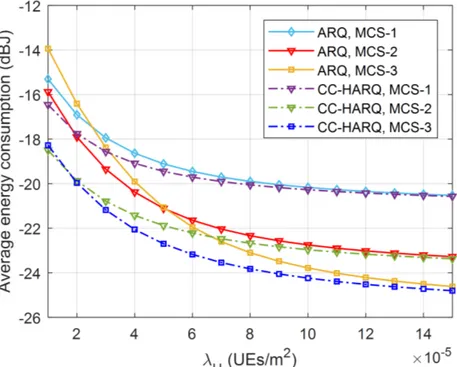
4.7 Average energy consumption of ARQ and CC-HARQ as a function of the UE density. . . 68
5.1 Network model where MTDs and UEs are randomly distributed in a single cell network. . . 75
5.2 Discovery area. . . 78
5.3 D2D relaying procedure. . . 79
5.4 Packet exchange sequence in our D2D relaying mechanism. . . 81
5.5 PMFs of the time slot choice in a network with four relay candidates. . . 83
5.6 Probability of finding at least one UE inside the discovery area. . . 94
5.7 Relay discovery probability as function of the UE density for Rd= 300. . . 94
5.8 Average number of time slots used in the contention process as function of the UE density for Rd= 300. . . 95
5.9 PDF of the MTD-relay distance. . . 96
5.10 Average energy consumption in the discovery phase, data transmission phase, and total in D2D mode. . . 97
5.11 Relay discovery probability as function of the UE density. . . 98
5.12 Average number of time slots used during contention process as function of the UE density. . . 99
5.13 PDF of the MTD-relay distance. . . 100
5.14 Total MTD energy consumption in D2D and cellular modes. . . 101
5.15 Optimal normalized radius of the discovery area. . . 103
5.16 Optimal b parameter. . . 105
5.17 Total MTD energy consumption in cellular mode and D2D mode versus UE density and the MTD-BS distance. . . 107
5.18 Total MTD energy consumption in cellular mode and D2D mode versus UE density and the data packet size. . . 109
A.1 Homogeneous PPP versus inhomogeneous PPP. . . 127
C.1 BLER versus number of repetitions for LTE-M PUSCH at 164 dB MCL. . . 138
C.2 BLER versus number of repetitions for LTE-M PDSCH at 164 dB MCL. . . 139
List of figures xv
D.1 Processus de relayage D2D. . . 143
D.2 Modèle de réseau avec allocation autonome des ressources. . . 144
D.3 Proposition d’un protocole de relayage D2D. . . 147
D.4 PMF du choix du time-slot dans un réseau avec quatre UEs. . . 148 D.5 Comparaison de la consomation d’énergie entre les modes D2D et cellulaire. 149
List of tables
2.1 5G requirements for mMTC . . . 9
2.2 3GPP cellular IoT specifications . . . 12
2.3 Periodicity of inter-arrival time . . . 12
2.4 Power consumption assumptions [3] . . . 16
2.5 LTE-M energy consumption at 164 dB MCL . . . 19
2.6 Total LTE-M energy consumption at 164 dB MCL . . . 20
2.7 Battery Life for LTE-M at 164 dB MCL . . . 21
3.1 UE densities considered in this work . . . 35
3.2 Parameters for the analysis . . . 44
4.1 Simulation parameters . . . 63
4.2 Transmission modes parameters . . . 63
4.3 Maximum number of transmissions N for 10% and 5% loss probability . . . 67
4.4 Energy reduction factor for loss probability less than 10% . . . 69
5.1 Simulation parameters . . . 93
5.2 Ranges of UE densities for relay discovery probability greater than 95% . . 98
5.3 Ranges of UE densities for less than 4 time-slots . . . 99
5.4 Ranges of UE densities for energy consumption less than 1.6 mJ . . . 101
5.5 Qualitative comparison for different values of b . . . 102
5.6 Optimal Rdand W parameters . . . 103
5.7 Percentage of the target UE density range where MTD energy consumption is minimal. . . 105
5.8 Energy reduction factor as a function of the UE density . . . 107
5.9 Energy reduction factor versus the data size for low UE density. . . 108
5.10 Energy reduction factor versus the data size for high UE density. . . 110
C.2 LTE-M PDSCH simulation parameters . . . 137 C.3 LTE-M PRACH simulation parameters . . . 139
Nomenclature
Acronyms / Abbreviations3GPP 3rd Generation Partnership Project 8-PSK 8-ary Phase Shift Keying
ACK Acknowledgement
ARQ Automatic Repeat Request AWGN Additive White Gaussian Noise BLER Block Error Rate
BS Base Station
CDF Cumulative distribution function CIoT Cellular Internet of Things
CP Control Plane
CTS Clear-to-Send
D2D Device-to-Device
DRX Discontinuous reception
EC-GSM-IoT Extended Coverage-GSM-IoT eDRX Extended Discontinued Reception eMBB Enhanced Mobile Broadband EPC Evolved Packet Core
FDD Frequency-division duplex FEC Forward Error Correction
GMSK Gaussian Minimum Shift Keying GSM Global System for Mobile
H-PPP Homogeneous Poisson Point Process H2H Human-to-Human
HARQ Hybrid Automatic Repeat reQuest
IoT Internet of Things
IP Internet Protocol
ISD Inter-site Distance
ISM Industrial, Scientific and Medical
SIC Successive Interference Cancellation
ITU International Telecommunication Union
LPWAN Low-Power Wide Area Networks
LTE-M Long-Term Evolution for Machine-Type Communications M2M Machine-to-Machine
MAC Medium Access Control MAR Mobile Autonomous Reporting MCL Maximum Coupling Loss
MCS Modulation and Coding Schemes MIB Master Information Block
MME Mobility Management Entity
mMTC massive Machine-Type Communication MRC Maximum Ratio Combining
Nomenclature xxi
MTC Machine-Type Communication MTD Machine-Type Devices
NB-IoT Narrowband Internet of Things NLoS Non-line-of-sight
OFDMA Orthogonal frequency-division multiple access
PDF Probability density function
PDSCH Physical Downlink Shared Channel PGW Packet data network gateway
PMF Probability Mass Function
PPP Poisson Point Process
PRACH Physical Random Access Channel PRB Physical Resource Block
PSM Power-saving mode
PSS Primary synchronization signal
PUSCH Physical Uplink Shared Channel QAM Quadrature Amplitude Modulation
QoS Quality of Service
RA Random Access
RC Relay-Candidate
RF Radio Frequency
RR Request-for-Relay
RRC Radio Resource Control
RTS Request-to-Send
SCEF Service Capability Exposure Function SGW Serving gateway
SIB System Information Block
SIR Signal to Interference Ratio
SMS Short Message Service
SSS Secondary synchronization signal
TAU Tracking Area Update
uMTC ultra-reliable Machine-Type Communication
UP User Plane
uRLLC ultra-Reliable Low Latency Communication
Chapter 1
Introduction
1.1
Context and Motivations
The era of fifth-Generation (5G) cellular network has arrived to meet the growing demand for new wireless communication services as well as to improve existing ones. The International Telecommunication Union (ITU) has classified the 5G services into three main categories [10]: (i) enhanced mobile broadband (eMBB), (ii) ultra-reliable low latency communication (uRLLC), and (iii) massive machine-type communication (mMTC). eMBB groups the tradi-tional services currently supported by cellular networks as well as the new applications that require a high data rate across a wide coverage area such as ultra-high-definition video, virtual reality. uRLLC groups the applications that require critical communications, with extremely high reactivity and reliability such as remote surgery, 3D gaming. mMTC applications, also known as massive Internet of Things (IoT), is characterized by a massive number of battery-powered and low-complexity devices that sporadically transmit small data packets, for example, wearables, smart meters, parking sensors, waste management, and many other use cases. Devices in this third category are called Machine-Type Devices (MTD)1.
Due to the huge number of potential mMTC applications, Cisco [11] and Ericsson [1] projections indicate exponential growth of the number of connections associated with these applications. There are currently different wireless technologies to cope with this growth, each connectivity technology having advantages and drawbacks depending on the use case. For short ranges, the most used technologies are Bluetooth [12], ZigBee [13], and Wi-Fi [14], which operate in unlicensed bands and have limitations in terms of Quality of Service (QoS) and security. There are other wireless technologies for mMTC applications, also known as Low-Power Wide Area Networks (LPWAN), which are specially designed
1The name MTD is used to refer to any MTC device, including those of the critical MTC applications.
to provide long-range connectivity. These technologies can be grouped into unlicensed LPWAN (or non-cellular LPWAN) and cellular IoT (CIoT) technologies. Unlicensed LPWAN technologies, such as LoRaWAN [15] and Sigfox [16], have been designed exclusively for long-range mMTC applications. The deployment of these technologies began a few years ago, and today they are important players of the IoT market. On the other hand, the 3rd Generation Partnership Project (3GPP) has proposed three CIoT technologies, namely, Extended Coverage-GSM-IoT (EC-GSM-IoT), Narrowband IoT (NB-IoT), and Long-Term Evolution for MTC (LTE-M). Each of the CIoT technologies was designed for specific use cases, while EC-GSM-IoT is compatible with GSM networks, LTE-M and NB-IoT are based on the fundamentals of LTE. Ericsson estimates that the global number of CIoT connections supported by NB-IoT and LTE-M will overgrow in the coming years, from 100 million in 2019 to 2.5 billion in 2025, i.e., half of the total number of IoT connections projected for that year (see Fig. 1.1).
Fig. 1.1 Expected growth of massive IoT connections (billion) [1].
One of the requirements related to mMTC applications is long battery life since it is often not viable to recharge or replace the batteries due to the considerable number of MTDs and their locations. Many MTDs are placed in locations with poor coverage, such as smart utility meters installed in the building basements, other devices are deployed in deep indoor scenarios suffering an extra penetration loss, such as smoke detectors. The method most used by CIoT technologies to improve coverage is the repetition technique [17], which consists of repeating the same transmission several times; for example, LTE-M supports up to 2048 repetitions [18]. However, the cost of this technique is the increase in both the use of radio resources and MTD energy consumption. The latter being a big issue for these kinds of applications since they require a long battery life, as mentioned above.
1.2 Contributions 3
In traditional cellular communications, all the devices involved in the communication have to establish a connection with the base station (BS). This approach, in some cases, is not the most efficient, especially when the communicating devices are located close to each other. LTE Device-to-Device (D2D) communication is a new approach that takes advantage of the proximity of the devices; it consists of the establishment of direct communication between nearby devices, i.e., the data transmitted does not pass through the base station. D2D communication is one of the key enablers for a variety of 5G services [19], includ-ing public safety services, content sharinclud-ing, coverage extension, vehicle-to-vehicle (V2V) communication, D2D relaying, etc.
In this thesis, we are particularly interested in D2D relaying, which consists of using a device as a relay to help another device that is in poor coverage. The idea is that an MTD with an unfavorable MTD-BS link budget can use a nearby UE (e.g., a smartphone) as a relay instead of transmitting its data directly to the base station wasting radio resources and energy. This new approach involves many challenges such as the allocation of resources for D2D communications, determining when it is convenient to use a relay instead of a direct transmission to the base station, the criteria for selecting a relay, the security of the D2D communication. We will show the advantages of using D2D technology for mMTC applications instead of traditional cellular communication. Our analysis focuses on the energy consumption of MTDs since we consider that this performance metric is one of the most critical requirements to take into account for these types of applications. A part of the work done in this thesis has contributed to the H2020 European project ONE5G [20].
1.2
Contributions
As mentioned before, this thesis focuses on the use of D2D relaying mechanisms to reduce MTD energy consumption. This approach considers that an MTD uses a nearby UE as a relay, establishing a D2D link between both devices. In order to have a tractable analytical model, we consider that the locations of MTDs and UEs form two independent Poisson point processes (PPPs), and then by using the stochastic geometry, we evaluate the performance of D2D communication and compare it with traditional cellular communication. The main contributions of this thesis are summarized as follows:
• Through simulations, we calculate the amount of energy consumed in each phase of the communication process for an MTD at 164 dB Maximum Coupling Loss (MCL) that uses LTE-M technology. In this analysis, we consider the parameters proposed by the 3GPP as well as the repetition mechanism.
• Using a simple model, we compare the energy consumption in cellular mode and the global energy consumption in D2D mode (i.e., the energy consumed by both the MTD and the relay). Based on this analysis, we determine the optimal location of the relay to minimize global energy consumption.
• In a scenario where the MTDs autonomously select the radio resources to be used for the D2D link, we analyze the performance of D2D communication with Hybrid Automatic Repeat reQuest with Chase Combining (CC-HARQ). Using stochastic geometry, we derive formulas for the transmission success probability, the average number of transmissions, and the MTD energy consumption. The performance of the Automatic Repeat reQuest (ARQ) is also analyzed as a reference.
• Considering that the MTD selects the best UE as a relay during the discovery phase, we analyze the performance of both ARQ and CC-HARQ. Then, we compare the performance of both retransmission schemes in terms of energy consumption for different modulation and coding schemes (MCS) levels and considering a target loss probability of 10%.
• We propose a D2D relaying mechanism suitable for mMTC applications thanks to its easy implementation and the amount of energy that it could save. This mechanism uses a distributed relay selection approach (i.e., without the participation of the base station), which prioritizes the selection of the UEs with the best channel qualities. • Using stochastic geometry, we provide an analytical framework to evaluate the
perfor-mance of our D2D relaying mechanism. We derive formulas for the relay discovery probability, the average number of time slots used in the contention process, the proba-bility density function (PDF) of the MTD-relay distance, and the total MTD energy consumption. These formulas are useful for determining the optimal values of the key parameters of our relay selection protocol.
1.3
Thesis outline
The remainder of this thesis is organized as follows:
In Chapter 2, we provide an overview of mMTC applications, including the key 5G requirements, the new cellular IoT technologies, the traffic models, and the energy consump-tion model. We also study the energy consumed by an MTD when sending an uplink report, according to the LTE-M specifications.
1.3 Thesis outline 5
In Chapter 3, we give background information about LTE D2D communication focusing on D2D relaying. Furthermore, in this chapter, we conduct a comparative analysis, in terms of global energy consumption, between traditional cellular communication and an approach that uses a D2D relaying mechanism for data transmission.
In Chapter 4, we show a performance comparison between ARQ and CC-HARQ in terms of the transmission success probability, the average number of transmissions, and MTD energy consumption in D2D communications. Then the analytical results are validated by simulations. As a particular case, we study a scenario where the MTDs select the best UEs as relays. Based on this analysis, we then compare both retransmission mechanisms as a function of the UE density.
In Chapter 5, we propose an energy-efficient D2D relaying mechanism. Through analyti-cal models, we study the performance of our relay mechanism based on the relay discovery probability, the average number of time slots used in the contention process, the probability to select a close relay, and the MTD energy consumption. Simulations validate the analytical results and then we discuss how the key parameter of our relay selection protocol affects performance metrics. Finally, we compare energy consumption when the MTD uses our relaying mechanism and when it uses a cellular transmission.
Chapter 2
Massive Machine-type Communication
Overview
2.1
Introduction
In 2007 the 3GPP initiated the studies related to the feasibility of Machine-Type Communi-cation (MTC) [21]. This group defined the MTC as a form of communiCommuni-cation involving one or more entities that do not necessarily need human interaction [22].
MTC applications are varied and have specific QoS features depending on the use case. They are often grouped into two categories [23], namely, ultra-reliable MTC (uMTC) and massive MTC (mMTC). uMTC applications are characterized by very low latency, high reliability and availability, and in fact, such applications are also part of URLLC 5G category defined in [10]. On the other hand, mMTC applications are characterized by a large number of devices, low mobility, small and infrequent data transmission, long battery life (e.g., smart meters or smart buildings). In this thesis, we focus on connectivity technologies for mMTC applications. Most MTDs are low complexity devices and must operate for many years entirely depending on a low-cost battery [24]. Furthermore, these devices are usually located in places where they suffer a considerable building penetration loss (up to 50 dB [25]) like deep inside buildings or basements. In other words, they generally have an unfavorable link budget. Therefore, the main challenges in mMTC applications are to ensure the connectivity of a massive number of MTDs without degrading the network performance and to reduce the energy consumed by the MTD without increasing the device complexity.
As new connectivity technologies dedicated to mMTC applications, LPWAN technolo-gies are distinguished by their ability to provide high coverage while using low energy consumption. These technologies may operate in licensed bands, also known as CIoT
tech-nologies such as EC-GSM-IoT, NB-IoT, and LTE-M or in unlicensed bands such as Sigfox, LoRa, and Ingenu [24].
The rest of this chapter is organized as follows: Section 2.2 presents the requirements of mMTC applications. The existing cellular IoT technologies designed for mMTC applications are compared in Section 2.3. The traffic model for MTC is shown in Section 2.4. Section 2.5 provides an overview of the MTC energy consumption, including the energy consumption model, an energy consumption analysis of LTE-M, and a survey about energy-efficiency for MTC. Finally, conclusions are drawn in Section 2.6.
2.2
mMTC 5G Requirements
From their inception with the traditional services (e.g., voice and SMS) to the most recent services (e.g., video calls and high-speed internet access), the requirements associated with cellular technologies were centered on humans. As a consequence, the complexity of UEs has evolved over the years; nowadays, one of the most used devices is the smartphone, which has a powerful processor and a high storage capacity. Nevertheless, with the emergence of MTC, many of these requirements become more relaxed, while others become more restrictive compared to human-centered cellular technologies.
MTDs usually perform a specific task and send a data report to the network; for example, smart utility meters send a monthly report. Due to the wide variety of use cases, the 3GPP considers that the network can support up to one million devices per square kilometer. Another characteristic of mMTC applications is the location of the MTDs; many of them are located in places of poor cellular coverage such as deep inside buildings or basements. For this reason, the coverage of the cellular network must be extended; the target for coverage is 164 dB of MCL for a data rate of 160 bps at the application layer [3]. Unlike human applications where the UEs are close to users, many MTDs are located in places of difficult access for humans. Therefore, an essential requirement to maintain low operating costs is the long battery life since recharging the device batteries or changing them would be a complicated task due to the location of the MTDs. For a daily data transfer of 200 bytes in uplink followed by 20 bytes in downlink at an MCL of 164 dB, the battery life must be more than 10 years (15 years is desirable) for a device battery of 5 Wh. MTDs are low-cost devices; this requirement is directly related to the low complexity device. Finally, a requirement less restrictive compared to human applications is the latency, mMTC applications can tolerate a delay of up to 10 seconds in uplink for a 20 bytes application packet (with uncompressed IP header) at 164 dB MCL. Table 2.1 presents a summary of the main requirements of mMTC applications based on [3, 26].
2.3 Cellular Internet of Things 9 Table 2.1 5G requirements for mMTC
Requirement Objective
Connection density The target for connection density in the urban environment is one million devices/km2
Coverage 164 dB of MCL for a data rate of 160 bps at the application
layer
UE battery life At least 10 years for a battery of 5 Wh, a daily data transfer
of 200 bytes uplink followed by 20 bytes downlink at 164 dB MCL
Latency Less than 10 seconds on the uplink for a 20 bytes application
packet (with uncompressed IP header) at an MCL of 164 dB
Complexity Ultra-low device complexity
Enhanced coverage is one of the key features of CIoT technologies. One of the main techniques used for this purpose is repetitions. This technique consists of repeating the same transmission several times, and then all transmissions are combined on the reception side. Ideally, doubling the number of repetitions a 3 dB gain is expected but also doubling the latency while reducing by half the throughput and spectral efficiency.
Regarding battery life, CIoT technologies propose the use of power-saving modes (PSM) and extended Discontinued Reception (eDRX) techniques to save energy when the IoT device is in inactivity periods. However, when the device is in an active state (Tx or Rx state), the coverage has a significant impact on the energy consumed by the device. For example, if the device is located in deep indoor, it will need large numbers of repetitions to successfully transmit its data. The greater is the number of repetitions, the higher is the energy consumption, and the shorter is the lifetime of the battery.
CIoT technologies introduce a series of features that reduce device complexity. Among the most important, we can mention the following ones: the limited frequency bandwidth (1.4 MHz for LTE-M and 200 kHz for EC-GSM-IoT and NB-IoT), only one antenna chain, half-duplex operation in frequency-division duplex (FDD) bands.
2.3
Cellular Internet of Things
Nowadays, cellular networks are widely deployed worldwide. They are formed by cells and base stations. A base station covers a particular area, providing connections to devices located within this area. Cellular networks were optimized for Human-to-Human (H2H) communication, but with the emergence of new applications, they are expected to become
the most attractive technology to support IoT services. They offer scalability, reliability, large coverage, low-cost deployment (reuse of the installed cellular network infrastructure), security, dedicated spectrum, and simplicity of management [27].
CIoT can support IP and non-IP data packets [28]. This hybrid solution allows data com-munication without any overhead for specific applications that do not need IP connectivity. The network architecture of the CIoT is based on the LTE architecture (see Fig. 2.1). The Control Plane (CP) and User Plane (UP) optimization mechanisms for CIoT are implemented on the Mobility Management Entity (MME), serving gateway (SGW), and packet data net-work gateway (PGW) entities. The standard also considers a new netnet-work entity, the Service Capability Exposure Function (SCEF). The interface between MME and SCEF is called T6a and is based on the DIAMETER protocol, which is adapted to transmit small amounts of non-IP data packets over the CP. As shown in the figure, on the new control plane CIoT, the radio access network switches the data between the UE and the MME. Then, the data is transmitted to the PGW via the SGW (IP data) or to the SCEF (non-IP data). With the user plane, both IP (legacy LTE) and non-IP data can be transferred via the SGW and PGW to the CIoT application server.
Fig. 2.1 CIoT network architecture (based on [2]).
3GPP standards developed three new technologies (EC-GSM-IoT, NB-IoT, LTE-M) dedicated to providing cellular services for mMTC applications.
2.3.1
LTE-M
LTE-M extends LTE technology with features to support mMTC applications requiring low to medium data rate [24]. It may provide low complexity, extended coverage, and improved
2.4 MTC Traffic Model 11
battery life while reusing the existing LTE cellular infrastructure. LTE-M operates on a lower system bandwidth of 1.4 MHz and provides bi-directional communication with a data rate of 1 Mbps. It uses single-carrier Frequency Division Multiple Access (SC-FDMA) with 15 kHz tone spacing for the uplink and orthogonal frequency-division multiple access (OFDMA) with 15 kHz subcarrier spacing and 16-QAM modulation for the downlink. LTE-M device is restricted to a maximum transport block size of 1000 bits and typically operates in half-duplex mode. Moreover, it supports PSM and eDRX to extend battery life.
2.3.2
EC-GSM-IoT
The EC-GSM-IoT is a new radio access technology for IoT [3]. It is compatible with existing GSM technologies and uses a system bandwidth of 2.4 MHz and 200 kHz per channel. Two modulation techniques for data transmission are considered, the Gaussian Minimum Shift Keying (GMSK) and 8-ary Phase Shift Keying (8-PSK), achieving a peak data rate of 10 kbps and 240 kbps, receptively. EC-GSM-IoT extends the coverage of the typical GSM by 20 dB using the repetition techniques. Moreover, this technology improves battery lifetime by using PSM and eDRX techniques. The maximum transmission power level of an EC-GSM-IoT device is either 33 dBm or 23 dBm.
2.3.3
NB-IoT
NB-IoT is one of the new cellular technologies proposed by the 3GPP [3]. This technology reuse some LTE technical components to facilitate the deployment in the existing LTE networks. The downlink is based on OFDMA with a system bandwidth of 180 kHz, i.e., one LTE Physical Resource Blocks (PRBs). In the uplink, it uses SC-FDMA with 3.75 and 15 kHz subcarrier spacing. NB-IoT may operate in three different modes: guard-band, in-band, and stand-alone. In guard-band mode, it uses an LTE carrier in the LTE guard-band. In-band mode, it uses one LTE PRB. In stand-alone mode, it may be deployed as a dedicated carrier using a bandwidth larger than 180 kHz (e.g., using one GSM channel of 200 kHz). NB-IoT may use battery-saving features such as PSM and eDRX. The maximum transmission power can be 20 dBm or 23 dBm.
A summary of the specifications of these three cellular technologies is shown in Table 2.2.
2.4
MTC Traffic Model
Table 2.2 3GPP cellular IoT specifications
EC-GSM-IoT NB-IoT LTE-M
Deployment In-band GSM In-band, guard-band,
standalone
In-band LTE
Coverage (dB) 164 164 155.7
Bandwidth 200 kHz per channel 180 kHz 1.08 MHz
Duplexing HD, FDD HD, FDD FD/HD, FDD/TDD
Power class 33 dBm, 23 dBm 23 dBm 20 dBm, 23 dBm
Power saving PSM, eDRX PSM, eDRX PSM, eDRX
2.4.1
Mobile Autonomous Reporting (MAR) Periodic Reports
The MAR periodic reports model is the most common traffic model in mMTC applications; it is used when the device periodically sends a report to the server. This report is self-triggered by the MTD based on its configuration. In this model, it is assumed that the server responds with an acknowledgment (ACK) in 50% of cases. The application payload size distribution is modeled as a Pareto distribution with shape parameter α = 2.5, the minimum payload size of 20 bytes, and the cut-off is 200 bytes. The payload size does not include the header size of the higher layers. The periodic inter-arrival time of this model is divided into four groups, which are shown in Table 2.3.
Table 2.3 Periodicity of inter-arrival time
Periodicity Percentage
1 day 40%
2 hours 40%
1 hour 15%
30 minutes 5%
2.4.2
MAR Exception Reports
The MAR exception reports model is used when the MTD is programmed to send a report when an exceptional event is detected (these events are expected to be rare). It is assumed an uplink application payload of 20 bytes and a latency target of 10 seconds.
2.5 MTC Energy Consumption 13
2.4.3
Network Command
The network command traffic model is used to model the traffic triggered by the server, either by requesting a report from the MTD or when sending commands to the MTD to perform an action. The size of the command (downlink) is 20 bytes, and its periodicity is similar to the MAR periodic reporting. For the uplink, the device responds with an ACK with zero bytes in 50% of cases, and in the remaining 50%, it responds with an uplink report with a payload size similar to the MAR periodic report.
2.4.4
Software Update/Reconfiguration
It is assumed that the device requires a software update/reconfiguration with a periodicity of 180 days. The application payload size distribution is modeled as a Pareto distribution with shape parameter α = 1.5 and a minimum payload size of 200 bytes with a cut-off of 2000 bytes.
Unlike human-centered applications, most mMTC applications are focused on uplink communications [29, 30]. In the network simulations, MAR exception reports and software update/reconfiguration traffic models are usually not considered since the frequency of occurrence is rare. It is considered that 80% of the cases the traffic is MAR periodic reports and 20% network command [31]. Therefore in this thesis, we will conduct a performance analysis of the uplink reports, i.e., when the MTD sends its data packets to the network. In [3], it is assumed 65 bytes for header size without IP header compression and 29 bytes with IP header compression. Therefore, the packet size of the MAR periodic reports, including the headers, varies from 85 bytes to 265 bytes for uncompressed headers, and from 49 bytes to 229 bytes for compressed headers. By using the formula of the truncated Pareto distribution given in [32], the cumulative distribution function (CDF) of the packet sizes of the uplink reports, including the header size, is shown in Fig. 2.2. As it can be observed from the figure, 50% of the reports have a packet size greater than 65 bytes and 110 bytes for compressed headers and uncompressed headers, respectively.
2.5
MTC Energy Consumption
2.5.1
Energy Consumption Model
The energy consumption is a crucial parameter to evaluate the performance of a CIoT technology. The 3GPP proposes a simplified energy state model to compute the total energy
Fig. 2.2 CDF of the packet size of uplink reports.
consumption [3]. This model consists of four states, and at a given time, the device operate in one of these states:
• Active Rx state: The MTD is actively receiving or attempting to receive a signal. • Active Tx state: The MTD is actively transmitting a signal.
• Idle state: The MTD maintains the accurate timing by keeping RF frequency reference active. In this state, the device wakes up to receive paging messages from the network so that it can be reached from the network.
• Power Saving state (Sleep): The MTD releases all radio connections; only the sleep clock is expected to be running. In this state the device is not monitoring paging, so it becomes unreachable from the network.
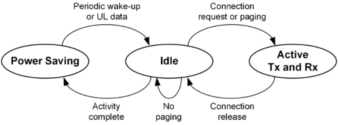
The MTD operating states, as well as the transitions, are shown in Fig. 2.3. The MTD in the sleep state is programmed to wake-up periodically and to switch to the idle state to read the paging channel. The MTD remains in the idle state for a specific time; if there is no new message to be transmitted, it goes into the sleep state (activity complete). The MTD moves from the idle state to the active state when it has uplink data to transmit (connection request). In the idle state, the MTD periodically moves to the active state to check whether there is any paging message for it from the network (paging). This periodicity is also known as the eDRX cycle. When the MTD has finished the transmission or reception of some information, it changes to the idle state (connection release) so that the base station can still reach it.
2.5 MTC Energy Consumption 15
Fig. 2.3 MTD operating states.
In order to calculate the total MTD energy consumption, it is necessary to estimate the proportion of time spent by the MTD in each state during a reporting cycle. A reporting cycle is defined as the time between the transmission of two consecutive data reports, as illustrated in Fig. 2.4. During this cycle, there is an exchange of messages between the MTD and the network. When the device has no data to transmit, it remains in the sleep state, and it wakes up periodically to perform a tracking area update (TAU), i.e., it moves to the idle state to monitor the paging channel in order to check whether there is data for it from the network. At the end of the idle phase, it returns to the sleep state until the next TAU. When the MTD has some data to transmit, it moves to the active state starting with the synchronization phase (system information) and then the connection establishment phase (Random Access procedure). Once the device establishes a connection with the network, it transmits its data and waits for an ACK. Finally, there is an idle phase before the device returns to the sleep state. In the example shown in the figure, we assume that all messages are successfully transmitted to the base station, i.e., the repetition technique is not used.
In the energy consumption model, each operating state has a specific and constant power requirement. When the MTD is in Tx state, the power consumption (energy consumption per unit time) is Pm,T = Pcirc+ Ptx/Aeff, where Pcircrepresents the power consumption due to the circuitry, Ptxdenotes the transmission power, and Aeffis the power amplifier efficiency. In [3], the 3GPP gives the parameters to be used in the energy consumption analysis. It is assumed a transmission power of 23 dBm, a power amplifier efficiency of 44%, and 90 mW for other analog and baseband circuitry. When the MTD is in Rx state, the Radio Frequency (RF) receiver circuit is active; in this state, the power consumption Pm,Ris considered constant. Let Pidle and Psleeprespectively be the power consumption during the idle, and sleep states. Thus, the total energy consumed by the device is computed as:
Etotal= Pm,Ttm,T + Pm,Rtm,R+ Pidletidle+ Psleeptsleep, (2.1)
where tm,T, tm,R, tidle, and tsleepare the proportion of time spent by the device in Tx, Rx, idle, and sleep states, respectively. The power consumption assumptions are given in Table 2.4.
Table 2.4 Power consumption assumptions [3]
MTD state Power consumption (mW)
Tx active 545
Rx active 90
Idle 3
Power saving (Sleep) 0.015
2.5.2
Energy Consumption Analysis for LTE-M
2.5.2.1 MTD Energy Consumption
As a complementary part of my thesis, in my research team at Orange Labs, an internship1 was carried out whose first objective was to develop link-level simulations for evaluating the performance of LTE-M, especially the data rate and MTD energy consumption. Appendix C shows more details about this work, including the simulation parameters. In this study, it is considered a scenario where the MTD is at 164 dB MCL and transmits a data packet of 200 bytes. The device is in coverage, and therefore, it is synchronized with the base station. In this study, it is shown that to guarantee a Block Error Rate (BLER) lower than 10%, the number of retransmissions for Physical Uplink Shared Channel (PUSCH) and Physical
2.5 MTC Energy Consumption 17
Downlink Shared Channel (PDSCH), are respectively 512 and 256. As a consequence, the data rate for PUSCH and PDSCH, are respectively 608 bps and 3364 bps. However, to determine the time of each message, we use the formula given by (C.2).
The energy consumption analysis includes all messages exchanged between the MTD and the base station from the Physical Random Access Channel (PRACH) preamble transmission to the connection release message. All the sequences of messages considered in the analysis are shown in Fig. 2.5.
When the MTD wakes up, it listens to the synchronization messages sent by the base station. After that, it starts the random access procedure by sending the Random Access Preamble(message 1); 64 repetitions are necessary to guarantee a PRACH detection probabil-ity of 99% (see Fig. C.3 in the Appendix C). The base station replies with a Random Access Response(message 2) which contains scheduling information such as the radio resources to be used by the MTD to transmit a RRC Connection Resume Request (message 3). The base station sends the RRC Connection Resume (message 4). The MTD transmits later the
RRC Connection Resume Completeand the RLC ACK for message 4 (message 5a); in the
same message, the Uplink Data is transmitted (message 5b). After transmitting its data, the MTD receives the RLC ACK for Uplink Data (message 6) and the Application Downlink (message 7) and the MTD responds with RLC ACK Downlink Data (message 8). The base station sends the RRC Connection Release (message 9) and finally, the MTD responds with an RLC ACK for Connection Realease (message 10).
Table 2.5 shows a summary of the energy consumed by the MTD for each message exchanged with the base station. The sizes of all messages and the power consumption in each state are similar to those used in [25]. From the table, we can see that message 5 (uplink data) consumes a little more than half of the total energy consumption. Besides, the random access procedure (from message 1 to message 5a) consumes almost a quarter of the total energy consumption. Fig. 2.6 illustrates how energy consumption increases with each message transmitted, reaching up to 2830 mJ at the end of the communication.
2.5.2.2 LTE-M Battery Lifetime
In this section, we estimate the number of years that an MTD at 164 dB MCL powered by a 5 Wh battery remains operational, assuming that it sends a 200 bytes uplink report and receives 65 bytes downlink acknowledgment. First, we calculate the energy consumed to send one report and then the daily energy consumption considering the MAR periodic report models. Before the sequence of messages illustrated in Fig. 2.5, the MTD executes a synchronization process, which includes the Primary Synchronization Signal (PSS), the Secondary Synchronization Signal (SSS), the Master Information Block (MIB) and the
2.5 MTC Energy Consumption 19
Table 2.5 LTE-M energy consumption at 164 dB MCL
Message Size (bytes) Time (ms) Energy (mJ) Percentage
1 64 36,8 1.30% 2 7 256 20,48 0.72% 3 7 512 294,4 10.40% 4 20 256 20,48 0.72% 5a 22 512 294,4 10.40% 5b 200 2631,6 1513,2 53.47% 6 3 256 20,48 0.72% 7 65 256 20,48 0.72% 8 3 512 294,4 10,40% 9 8 256 20,48 0,72% 10 3 512 294,4 10,40%
System Information Blocks (SIB). In addition to these messages, it will also be considered one second of waiting time in light sleep between the uplink transmission and the downlink ACK, twenty seconds in light sleep after the release in case the eNB sends more information, and the rest of the time PSM. The duration of all these messages is given in [25]. Table 2.6 summarizes the energy consumption of all messages exchanged between the MTD and the base station for the transmission of a report. In total, the MTD consumed 3035.4 mJ per report and remains active for 28.8 seconds.
Table 2.6 Total LTE-M energy consumption at 164 dB MCL
Procedures Time (s) Power (mW) Energy (mJ)
PSS/SSS 0.88 80 70.4
MIB 0.25 80 20
SIB 0.65 80 52
Waiting DL ACK 1 3 3
Waiting before PSM 20 3 60
Message sequence (Fig. 2.5) 6.02 2830
Total 28.8 3035.4
To determine the battery life, we consider the same inter-arrival time periodicity given in Table 2.3. First, we determine the daily reports Nreport and then the daily MTD energy consumption in active state Eactive, which can be computed as Eactive= NreportEreport, where Ereport= 3035.4 mJ is the total energy consumption per report. The daily energy consumption when the MTD sleeps can be derived as Esleep= tPSMEPSM, where tPSMis the time the device sleeps during the day; it can be computed as tPSM= 86400 − 28.8Nreport seconds. Thus, the total daily energy consumption can be computed as Etotal= Eactive+ Esleep. Then, we can determine the number of years that the MTD powered by a 5 Wh battery can remain operative. Table 2.7 resumes these calculations. From the table, we can see that the battery lifetime requirement (greater than ten years) is met only when the period is one message per day.
2.5.3
Related Studies on Energy-Efficient MTC
Optimization of energy consumption is one of the main challenges for mMTC applications. In this section, we present how some authors address this problem in a cellular IoT context. Typically MTDs transmit or receive data sporadically. Taking advantage of the fact that MTDs are inactive for a long time, 3GPP introduces two new techniques to improve the
2.5 MTC Energy Consumption 21 Table 2.7 Battery Life for LTE-M at 164 dB MCL
Periodicity Daily reports Total energy (J) Battery life (years)
1 day 1 3.035 11.39
2 hours 12 36.425 1.31
1 hour 24 72.850 0.67
30 minutes 48 145.699 0.34
battery life of these devices: the PSM and the eDRX. Fig 2.7 illustrates both PSM and eDRX techniques.
Fig. 2.7 PSM and eDRX techniques (based on [5]).
2.5.3.1 Power Saving Mode
Power Saving Mode is specified by the 3GPP Release 12 [28]. This mode allows to improve the battery life of MTDs since the device sleeps for long periods. The power consumption is significantly minimized while the device is not transmitting or receiving anything. When the device is dormant, it is unreachable for the network since it is not monitoring the paging messages sent by the base station; however, it remains registered with the network. The device using PSM wakes up for data transmission or a periodic TAU. After that, the device remains reachable for a short time before it goes back to sleep.
2.5.3.2 Extended Discontinued Reception
The discontinuous reception (DRX) technique consists of periods of sleep and wake-up to check whether the device has a paging message from the base station. The device must be synchronized with the base station, and it has to read the control messages every specific period. The eDRX technique [33], proposed by the 3GPP Release 13, allows a greater
reduction of MTD energy consumption. This technique extends the DRX cycles up to 40 minutes to allow an MTD to stay longer in sleep state between paging occasions.
In [34], the authors propose an Enhanced PSS (ePSS) and a novel DRX mechanism. The objective is to reduce the re-synchronization time and thus the device energy consumption. This ePSS can also be used to reduce the paging message processing time when there is no paging message for the MTD. In [35], the authors combine the mechanisms of relaying and DRX and propose an energy-efficient relay selection scheme. The results show that when the relays use the DRX, they can significantly reduce their energy consumption
The general objective of an MTD is to transmit some information to the network so it must establish communication with the base station. Nevertheless, it must first synchronize with the base station and then start the random access procedure before transmitting its data. The goal of many studies in the literature is to minimize the energy consumption of the synchronization and random access procedure.
2.5.3.3 Energy-Efficient Synchronization
Synchronization is the first step that a cellular device must perform in order to transmit or receive some information. In the case of MTDs, the fundamental issue is the longer synchronization acquisition time, which occurs due to the long period that these devices remain sleeping. This problem was addressed in [36, 37].
Some studies seek to save energy by reducing the computational complexity of the synchronization. In [36], the authors propose two low complexity algorithms for SSS detection to resynchronize quickly. The computational complexity and energy consumption are reduced while maintaining performance similar to the conventional method. In [37], the authors propose the use of simply-differential correlation-based timing synchronization based on Zadoff-Chu sequences. They suggest reducing the computational complexity using a recursive implementation simply differential metric.
In [34], the authors show that in the synchronization process, the energy consumption due to computational calculations is negligible in comparison to the energy consumption when the device is in the active state. They propose a novel DRX scheme for fast re-synchronization and thus to reduce the MTD energy consumption in this phase.
2.5.3.4 Signaling Overhead Reduction
Once the device is synchronized, the second step is to try to establish a connection with the base station through a random access procedure. During this procedure, there is an exchange
2.6 Conclusion 23
of control messages between the MTD and the base station, consuming a significant amount of energy. Therefore some authors aim to optimize this procedure.
One solution is the Radio Resource Control (RRC) resume procedure [38]; in this procedure, the goal is to optimize the number of signaling messages that are needed to establish a connection in LTE. The authors in [39] propose the use of a Polling service with a wide range of periods. This proposition takes into account the periodicity of most MTC traffic. This solution reduces the signaling overhead avoiding the collision caused by the random access.
In [40], the authors propose that MTDs use a buffer for packet aggregation. The random access only triggers if the number of packets in the buffer reaches a certain threshold. The optimization of energy configures the threshold value. This method saves energy by reducing the number of random access procedures. However, the drawback would be additional access latency due to the accumulation of several packets in the buffer. An improvement to this technique is presented in [41]. In this study, a new packet generated by an MTD does not remain in its buffer, but it is transferred to a neighboring MTD that have the number of packets in its buffer close to a threshold value. Thus, the number of random access procedures and the waiting time of a packet in the buffer are reduced.
2.6
Conclusion
In this chapter, we give an overview of mMTC applications and a brief survey about energy efficiency for these applications. We summarize the main requirements and the new cellular technologies for mMTC applications. An essential section of this chapter is the model of energy consumption which will be used in later chapters.
Among the MTC requirements identified, the most challenging and that have received the most attention from the research communities are the coverage and the device battery life. In order to improve the device battery life, the 3GPP proposes the PSM and eDRX techniques, which allow the device to sleep for long periods; however, the disadvantage of these techniques is that the device remains reachable for a short time. To extend the coverage, the 3GPP proposes the use of techniques such as repetitions, which is simple but effective to meet the coverage requirement. However, the main disadvantage of this technique is the high energy consumption, especially when the device is in poor coverage and requires a large number of repetitions.
In order to reduce the energy consumed during the exchange of messages between the MTD and the base station, in the literature the authors address their research on two
objectives, the first approach is to reduce the energy consumed during synchronization and the second approach is to reduce the energy consumption due to the control messages.
Through simulations according to the LTE-M specifications, the energy consumed by an MTD located at the cell border that sends a 200 bytes uplink report has been calculated. The results show that the data message represents half of the total energy consumption and the rest of the energy consumed is due to the control messages. A percentage of the total energy consumption could be reduced by reducing the number of control messages. However, a greater reduction would be achieved by reducing energy consumption during data transmission. To reduce energy consumption in the data transmission phase, the path loss between the MTD and the base station must be reduced. In this sense, the idea of using a relay is an exciting alternative to reduce energy consumption and extend the coverage. This technique will be detailed in the next chapter.
Chapter 3
D2D Communications Overview
3.1
Introduction
In traditional cellular communications, all communications pass through the base station. This configuration is not very efficient in some cases like when the UE is far from the base station; as an alternative to solve this problem appears the idea of D2D communication in cellular networks. D2D communication in mobile networks (LTE-D2D) is defined as direct communication between nearby devices without going through the base station. It is a promising technology to improve the performance of cellular networks since it takes advantage of the proximity for efficient use of radio resources, improving data rates, reducing latency, and improving energy efficiency. For this reason, it is being considered as a key enabling technology in 5G cellular networks [42].
D2D communication is not a new technology; it has been used mainly in non-cellular technologies (in the unlicensed band) such as Bluetooth, Wi-Fi Direct, ZigBee. These non-cellular technologies can also establish direct communication between devices, but in general, they have low spectrum and energy efficiency, short communication distance, and vulnerability to interference [43]. These problems are addressed more efficiently by LTE-D2D technology [44].
Initially, D2D communication was proposed for public safety services [45]. However, as shown in many studies reported in the literature there are many other potential use cases such as extending network coverage [46], offloading network coverage [47, 48], social proximity services [49], D2D relaying [50–53], V2V communication [54], local multicasting [55]. The possible D2D use cases are summarized in Fig. 3.1.
Although in some new use cases, D2D communication has advantages over traditional cellular communications, there are still many challenges that this technology must overcome in order to be successfully implemented in the future mobile network. Some of these
Fig. 3.1 D2D communications use cases [6].
challenges are efficient discovery, interference management, power allocation, resource allocation, and security.
The remainder of this chapter is organized as follows: Section 3.2 shows how D2D communication is categorized according to the use of the frequency spectrum. Section 3.3 describes the LTE D2D technology including the architecture, the functionalities, and the resource allocation modes. The D2D relaying technique is presented in Section 3.4. A survey about the D2D relaying for mMTC is given in Section 3.5. In Section 3.6, we present a comparative study that shows the interest of D2D for mMTC, the content of this section has been published in [56] and [57]. Finally, Section 3.7 concludes the chapter.
3.2
Spectrum Resource for D2D Communication
According to the use of the spectrum resource, D2D communication can be categorized into two groups [58]: inband D2D when it occurs on the cellular spectrum and outband D2D when it occurs on the unlicensed spectrum, usually on the industrial, scientific and medical (ISM) bands. In the case of inband, devices communicate directly using the cellular spectrum of their network provider, i.e., both cellular and D2D communications share the cellular spectrum. Inband D2D can be divided into two subgroups: underlay (non-orthogonal) and
3.3 D2D LTE 27
overlay (orthogonal). In underlay inband D2D, the same resources are used in cellular and D2D communications, which could cause interference between both types of communication. In overlay inband D2D, a group of the cellular resources is dedicated to D2D communications which avoid interference. Fig. 3.2 illustrates the different categories of D2D communications according to the use of the spectrum. In this thesis, we will focus on LTE D2D technology in overlay inband in order to mitigate interference between D2D and cellular communications. In other words, we assume that the BS allocates dedicated resources for D2D links.
Fig. 3.2 Spectrum resource for D2D communication.
3.3
D2D LTE
3.3.1
Architecture
The 3GPP specifies the D2D architecture in [8]; it is based on the conventional LTE architec-ture, but introduces a new entity, called Proximity Services (ProSe) function, in the Evolved Packet Core (EPC) (see Fig. 3.3). The ProSe function is a logical function and its primary role is to provide configuration and authorization to UEs for discovery and direct communication and to manage the ProSe context of the UEs. Moreover, this function authorizes UE the use of a specific ProSe application.
Two new logical interfaces, PC3 and PC5, are introduced. A UE that wants to use a Prose application must first contact the ProSe function by exchanging messages via the PC3 interface. Once the UE is authorized, it can initiate the process of discovery or
communication with other UEs via the PC5 interface. Sidelink is the terminology to refer to the direct communication over PC5.
The uplink channel is reused for sidelink since (i) the interference from the D2D link to the base station is limited, and (ii) higher D2D energy efficiency is obtained adopting the SC-FDMA [43].
Fig. 3.3 Simplified D2D architecture (based on [7]).
3.3.2
Functionalities
The 3GPP defines two main functionalities for supporting LTE D2D, namely, discovery and communication. When the UEs are in-coverage, these functionalities can be network assisted, i.e., the base station can transmit configuration and control information to the UEs.
3.3.2.1 D2D Discovery
D2D discovery allows the detection of useful information provided by the UEs in physical proximity. The 3GPP specifies two direct proximity discovery protocols [8], namely, model A and model B, which are represented in Fig. 3.4. Model A (“I’m here”) supports both open and restricted types of discovery. In this model, there are announcing UEs and monitoring UEsthat monitor information of interest from announcing UEs. Model B (“Who is there?”), used mainly for restricted type. In this model, only the UEs willing or authorized to help the source UE will respond. Two roles are defined: the discoverer UE, which transmits a request containing information about what is interesting to discover, and the discoveree UE, which receives the request and can respond with information related to discoverer’s request.
3.3 D2D LTE 29
Fig. 3.4 Public safety direct discovery with Model A and Model B [8].
3.3.2.2 D2D Communication
D2D communication allows to establish direct communication between UEs without passing through the base station. However, before establishing communication between UEs, these devices must know in advance if they are close to each other. For this reason, it is often considered that D2D communication is preceded by a discovery phase.
3.3.3
Radio Resource Allocation for Sidelink
In D2D discovery and D2D communication, resource allocation can be performed in two modes: scheduled and autonomous.
3.3.3.1 Scheduled Mode
In this mode, the UE requests resources from the base station via radio resource control (RRC) signal; the base station assigns resources that the UE should use in the D2D link. This mode is similar to the allocation of resources in traditional cellular communications; therefore, it is feasible only when the UEs are in coverage. In the case of sidelink discovery,

![Fig. 3.1 D2D communications use cases [6].](https://thumb-eu.123doks.com/thumbv2/123doknet/11583054.298212/49.892.165.698.158.568/fig-d-d-communications-use-cases.webp)
![Fig. 3.4 Public safety direct discovery with Model A and Model B [8].](https://thumb-eu.123doks.com/thumbv2/123doknet/11583054.298212/52.892.231.686.163.579/fig-public-safety-direct-discovery-model-model-b.webp)