HAL Id: hal-01688099
https://hal.archives-ouvertes.fr/hal-01688099
Submitted on 24 Jul 2018
HAL is a multi-disciplinary open access
archive for the deposit and dissemination of
sci-entific research documents, whether they are
pub-lished or not. The documents may come from
teaching and research institutions in France or
abroad, or from public or private research centers.
L’archive ouverte pluridisciplinaire HAL, est
destinée au dépôt et à la diffusion de documents
scientifiques de niveau recherche, publiés ou non,
émanant des établissements d’enseignement et de
recherche français ou étrangers, des laboratoires
publics ou privés.
The effect of punch’s shape on die compaction of
pharmaceutical powders
Moulay S. Kadiri, Abderrahim Michrafy
To cite this version:
Moulay S. Kadiri, Abderrahim Michrafy. The effect of punch’s shape on die compaction of
pharmaceu-tical powders. Powder Technology, Elsevier, 2013, 239, pp.467-477. �10.1016/j.powtec.2013.02.022�.
�hal-01688099�
The effect of punch's shape on die compaction of pharmaceutical powders
M.S. Kadiri
a,⁎
, A. Michrafy
baUniv Hassan 1, ENSA, Equipe MO2P, BP 77 Khouribga, Morocco
bUniversité de Toulouse, Mines Albi, CNRS, Centre RAPSODEE, Campus Jarlard, F-81013 Albi Cedex 09, France
a b s t r a c t
Keywords: Powder compaction Punch's shape effects Density distribution Stress distribution Finite element modelling Numerical simulation
This paper investigates the compaction of pharmaceutical powders using different shapes of punches. We in-troduce a model of mechanical behaviour Drucker–Prager Cap (DPC), using the approach of compressible continuous media. The model parameters that are depending on the material density, were identified from experimental data and a calibration process was applied on Microcrystalline Cellulose (MCC) powder. In ad-dition, the mathematical formulation of the boundary problem of compaction in rigid tools brings back to an optimization problem with constraint, which is solved by finite element method. The Drucker–Prager Cap model, which is implemented in Abaqus/Standard software, was employed using a user subroutine, USDFLD. Three kinds of typical pharmaceutical tablets are considered: flat-face tablet and concave face tablet with two different depths. Results of simulations of die compaction cycle as compression, decompression and ejection, reproduce the powder compaction process for the studied shaped punches. The effects of the punch's shape on the compaction process were observed on the distribution and the maximum of stress and density in the compact. Examination of the density gradient according to the shape, suggests a capping tendency, which in-creases with the punch depth. This study illustrates the potentiality of the FEM method, which could be used as an efficient tool to predict the density and the stress distributions into shaped compacts and to provide a diagnostic of the capping problems.
1. Introduction
The pharmaceutical industry has invested vast amounts of time and money in the study of the powder compaction. This expenditure is quite reasonable because the tablet can be self-administered by the patient; it can be manufactured with several forms and different col-ours and introduces a constant dose of active ingredient. The tablet is obviously more profitable to manufacture than parenteral dosage forms that must be administered, in most cases by trained personnel. So, more than 80% of the drugs in USA are formulated to produce oral dosage forms. Compared to oral dosage forms, tablets are the manufacturer's dosage form of choice because of their relatively low cost of manufacture, package and increased stability[1]. Contrary to the metallic powders, the compression of pharmaceutical powders has no difficulties linked to the complicacy of the tablet shape. We find simple forms in general (flat, concave…). As a result, the difficul-ty of the flow of material for complex forms does not meet (or little) in the pharmaceutical tablets. However, several phenomena may lead to non-conformity of tablets. The friction between powder and die during the compaction process leads to heterogeneity of the density distribution into the tablet. This heterogeneity continues during the decompression and ejection phases and leads to a dispersion of
mechanical characteristics and sometimes to heterogeneity of the ac-tive ingredient for the scored tablets. Because of the powder proper-ties and the parameters of compaction process, the tablet expansion during decompression and ejection phases is well known in the phar-maceutical industry as a redoubtable phenomenon for production. Thus, the interest to control the compaction process parameters and to analyse the fundamental properties of powders is very important. The aim of the pharmaceutical powder compaction is to produce a good tablet without capping, with a sufficient mechanical strength, with uniform weight and with other properties. However, considering the powder (or powder mix) properties, which are very sensitive to handling, to provenance, or to manipulation, the success of the com-paction process and the manufacturing of a good tablet need an un-derstanding of the fundamental properties. These properties, which can be physicochemical and/or mechanical, allow explaining how a formulation could act during compaction.
Moreover, unsuccessful tablets are not always due to formulation. The process parameters as speed of compaction, punch shape, lubrica-tion[2], temperature[3]and humidity changes, and state of mainte-nance of punches and die are often responsible of disturbance during production.
Considering the fact that about 70% of pharmaceutical tablets are biconvex, we are interested in this work by the effect of the punch shape on the powder behaviour during compaction.
The computational modelling of powder compaction has typically been carried out by two different approaches: the discrete method
⁎ Corresponding author. Tel.: +212 600626210. E-mail address:kadiri@enstimac.fr(M.S. Kadiri).
and the continuum method. In this work, the continuum model meth-od was used. The compaction behaviour of pharmaceutical powders can be studied using the principles of continuum mechanics at macro-scopic level, i.e. phenomenological models. A variety of continuum models from the soil mechanics literature have been developed from experiments on different geo-materials as described by Drucker et al.[4], Schofield and Wroth[5], Di Maggio and Sandler[6], Gurson
[7]and Green[8]. Most of these models are governed primarily by el-liptical caps that determine the densification yield loci during the compaction process. However, elliptical caps fail to capture the shear-ing phenomenon in powders, which is extremely important durshear-ing the decompression and the ejection phases of powder compaction. Only the Drucker Prager/Cap (DPC) model is able to capture these phenomena because of the presence of a shear yield surface in addi-tion to an elliptical cap. Hence, the DPC model has gained wide accep-tance as a good constitutive model for modelling powder compaction. DPC models have been used for the analysis of compaction of phar-maceutical powders. These models can represent the densification and hardening of the powder, as well as the interparticle friction. DPC model have been used for pharmaceutical powders by A. Michrafy et al.[2], S. Kadiri et al.[9,10], J.C. Cunningham et al.[11], C.-Y. Wu et al.[12], G. Frenning[13], and recently by L.H. Han et al.[14]and T. Sinha et al.[15,16].
This work investigates the pharmaceutical powder compaction in cylindrical flat and curved punches. The approach is based on the detailed calibration of the powder behaviour in flat punch using DPC model and the analysis of punch curvature effects on the density dis-tribution during the compaction cycle. The material parameters of the model were identified by an experimental procedure. Numerical simulation of the compaction process using finite element method, gives us access to displacement, strain and stress fields in the tablet. The unloading and ejection phases are often neglected or the reso-lution method is not specified. Because the structure must release strain energy to remain in equilibrium, it is important to use adequate methods to avoid unstable response. In this study, the unloading step was simulated successfully using the Riks method, implemented in Abaqus. Results of the distribution of density gradients according to the punch deep curvature and tendency to the capping of tablets were discussed.
This paper is organized as follows:Section 2presents the mate-rials and methods; results are introduced in Section 3, where we present the experimental results of parameter identification and the numerical simulations. Finally,Section 4summarizes the conclusions. 2. Materials and methods
2.1. Materials
The microcrystalline cellulose Vivapur® 102 (MCC 102) is often used as a pharmaceutical excipient. Characteristics of the powder MCC 102 provided by JRS (J. Rettenmaier and Sohne) is shown in
Table 1. This powder having good flowability, compressibility and compactability, was used to identify the model parameters. A scan-ning electron microscopy image of the powder MCC 102 is presented inFig. 1.
The bulk density which is defined as the ratio of the mass over the volume of powder, is determined by measuring the volume of a known mass of powder sample, that may have been passed through a sieve into a graduated cylinder, or a measuring vessel, or by measur-ing the mass of a known volume of powder that has been passed
through a volumeter into a cup. The bulk properties of powders de-pend on preparation, treatment and storage of the sample, i.e. how it was handled. In this work, various masses were filled in a graduated cylinder with a known diameter. The obtained bulk density of MCC 102 is approximately 0.31 ± 0.01 g/cm3.
In addition, the relative density is expressed as:
Relative density ¼ Bulk density=True density: ð1Þ
Thus, the initial relative density ρ0is equal to 0.195. 2.2. Drucker–Prager Cap model
A short presentation of the DPC model is made here. For more de-tails, this model was described in several papers[9,12,14–16]. The Drucker–Prager Cap model is implemented in the Abaqus Software. The yield function is defined with three surfaces represented in
Fig. 2: the shear failure surface Fsdefining the correlation between the cohesion d and the internal friction angle β, the elliptical surface (or cap surface) Fcwhich can expand or contract according to the vol-umetric strain and the transition surface Ftbetween Fsand Fc. The evolution of the cap surface is described with the hardening function pbwhich is the position of the cap on hydrostatic pressure axis for each density state.
p= 1/3(σx+ σy+ σz) hydrostatic (compressive) stress; q = {(1/2) [(σx− σy)2+ (σy− σz)2+ (σx− σz)2]}1/2 Mises equivalent shear stress; where σx, σy, and σzrepresent the principal directions of stress. Six parameters are required to define the yield surface of the mod-ified DPC model: β, d, pa, R, pband α and two elastic parameters, Young's modulus E and Poisson's ratio ν, are required for describing the elastic behaviour of powders. In order to identify these parame-ters, we use experimental tests with instrumented die, shear cell and diametrical crushing.
The powder is characterized by mechanical properties (d, β, E) which evolve with the relative density of the powder, a constant
Table 1
Properties of MCC Vivapur® from J. Rettenmaier and Sohn.
Powder Mean particle size True density Bulk density MCC Vivapur 102 90 mm 1.59 ± 0.002 g/cm3 0.31 ± 0.02 g/cm3
Fig. 1. Scanning electron microscopy image of powder MCC (Vivapur® 102).
Poisson's ratio and an evolution of the hardening function pbwith vol-umetric plastic strain during compression.
For a cylindrical and homogeneous compact (state of the powder bed during compression in a cylindrical die well lubricated for in-stance), the hydrostatic pressure stress is expressed as:
p ¼ 1=3 σð zþ 2σrÞ
and the Mises equivalent stress is expressed as: q ¼ σj z−σrj
where σzand σrare the axial and radial stresses, respectively.
2.3. Material parameter identification for the DPC model 2.3.1. Cohesion and internal friction angle
Cohesion and internal friction angle have been characterized by measurement of tensile strength by axial and diametrical crushing under the hypothesis that the behaviour of the tensile strength is de-scribed by Drucker–Prager model (linearity between applied hydro-static pressure and maximal shear).
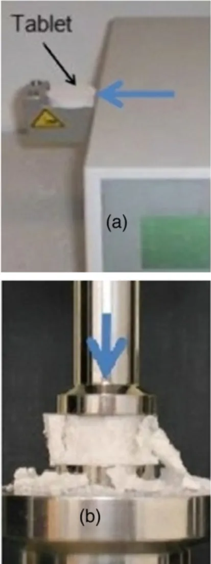
The diametrical crushing load was measured with the Erweka® TBH 30 apparatus (Fig. 3a). The axial crushing load was measured by an Instron® press (Fig. 3b). These tests were performed on tablets of MCC Vivapur 102 prepared with a cylindrical die with section of 1 cm2.
In order to use these tests with the DPC model, we have to write them in the p-q plane.
For diametral test, the coordinates of the point A of the failure line (Fig. 4) are:
p ¼ 2σD=3 and q ¼ 13ð Þ1=2σD ð2Þ
where σD= 2F/πDt is the tensile strength, F is applied load, t thick-ness of the tablet, D diameter of the tablet. In diametral crushing test, the principal directions of stress are σx=−σDand σy= 3σD. For more details, an analysis of the diametral test is published by Procopio et al.[17]and for more theoretical study[18,19].
For uniaxial test, the coordinates of the point B of the failure line (Fig. 4) are:
p ¼ σz=3 and q ¼ σz ð3Þ
where σzis the axial failure stress, and principal directions of stress σx= σy= 0.
Fig. 4introduces a graph locating axial and diametral tests in DPC model.
We note inFig. 4that both parameters d and β can be absolutely identified from diametral and uniaxial tests. Indeed, we can determine both points A and B corresponding respectively to tensile strength and axial failure stress. For every state of density, we have a unique failure line which passes by both points A and B. Thus, the cohesion d and the angle of internal friction β will be identified.
2.3.2. Cap shape parameter R and hardening function pb
The position of the cap shape is determined by the cap shape pa-rameter R and hydrostatic compression yield stress (hardening func-tion) pb. The parameter R is the eccentricity of the ellipse, which defines the cap. InFig. 5, the point B(p,q) corresponds to the end of compression. This point is on the surface Fcand proves the following equation[20,21]:
p−pa
ð Þ2þ Rq= 1 þ η−η= cos βð ð ÞÞ2
h i1=2
–R d þ pð atan βÞ ¼ 0 ð4Þ
where η is a small number (typically 0.01–0.05) used to define a smooth transition surface between the shear failure surface Fsand
Fig. 3. (a) Diametrical crushing with the Erweka® TBH 30 apparatus; (b) Axial crushing test with Instron® Press.
the cap Fc. To simplify the calculations, we took 1 + η− η/cos β ≈ 1. The equation of Fcbecomes:
p−pa
ð Þ2þ Rqð Þ2−R2ðd þ patan βÞ2¼ 0 ð5Þ
where pais the centre of the ellipse (seeFig. 2). The pressure pais de-termined by:
pa¼ pð b−RdÞ= 1 þ R tan βð Þ: ð6Þ
First, we identify both parameters R and pa. In addition to Eq.(5), it is necessary to introduce a second equation that will be deduced as follows.
Considering the associated flow rule in the cap region Fc, the incre-ment vector of inelastic strain dεinis normal to the cap F
c. The strain increment vector dεincan be decomposed in a volumetric component dεp= dεvoland a deviatoric component dεq:
dεp¼ dεvol¼ 2dεrþ dεz dεq¼ 2=3ð Þ dεð z−dεrÞ ð7Þ
where dεris the radial strain increment and dεzis the axial strain increment.
By neglecting the radial strain to the strain deformation in die compaction, we can write:
dεp=dεq¼ 2=3: ð8Þ
Eq.(8)shows that the slope of the normal to the cap Fcin the point B(p,q) is equal to 2/3. Therefore, the slope of the tangent to the cap on Bis equal to−3/2, thus:
dq=dp ¼ − p−pð aÞ= R2q
! "
¼ −3=2: ð9Þ
Combining Eqs.(5) and (9), we obtain the following polynomial:
2 tan2β ð Þ= 3qð Þ h i pa2þ 4d tan β½ð Þ= 3qð Þ þ 1&paþ 2d2 ! " =ð Þ− 2=33q ð Þq−p h i ¼ 0: ð10Þ
Solving Eq.(10)determines the parameter pa. The eccentricity R is deduced from Eq.(9)and consequently the hardening function ppis calculated from Eq.(6).
It is also possible to determine the parameters R and pbthrough measurements from a triaxial compression test commonly used in metal powders.
2.3.3. Elastic parameters (Poisson's ratio and Young's modulus) 2.3.3.1. Poisson's ratio ν. The die is supposed to be rigid and conse-quently the radial strain is null. Hooke's law states that:
σr−v σ# zþσr$¼ 0
where ν is the Poisson's ratio.
We measured the transfer ratio (ratio of the radial stress to the axial stress) of MCC Avicel PH102 for different temperatures (from elastic range to plastic deformation)[3]. The compaction was made in a cylindrical die of 11.28 mm in diameter and at ambient temper-ature (T = 20 °C), with an aspect ratio equal to 0.22 (H = 2.5 mm, D = 11.28 mm) that gave a transfer ratio α approximately constant
Fig. 5. Decomposition of the strain increment vector.
Fig. 6. Axial crushing test.
Fig. 7. Two cycles loading–unloading by compression of MCC Vivapur 102 tablet.
Fig. 8. Strengths of MCC Vivapur 102 tablets: (a) diametral tensile strength σD; (b) axial
in the range 0.4–0.45, which is similar to the values given in the liter-ature[10,24]. So, if we write:
σr¼ ασz
and with the Hooke's law[22,23]: ασz−v σð zþ ασzÞ ¼ 0
then; α= 1 þ αð Þ ¼ v:
It follows that, during the loading phase, the evolution of the ratio α/(1 + α) varies slightly from 0.29 in the elastic step to the value 0.31 for the plastic behaviour. In the following, we assumed the value 0.29 for the elastic Poisson's ratio and the value 0.31 for the plastic Poisson's ratio. This last value reaches 0.5 for metallic powders at full density.
2.3.3.2. Young's modulus.The axial compression (without die) is used to estimate the Young's modulus E (Fig. 3b). We use the macroscopic re-sponse of tablet that is given by the stress–strain curve. A cylindrical tablet of MCC Vivapur 102 is placed between two punches (Fig. 6). The upper and lower punches were lubricated with a magnesium stea-rate to reduce the role of friction that leads generally to a non-uniform stress state. Tablets was prepared with a cylindrical die (Height = 90 mm) and (Section = l cm2), with respect to the condition Height/ diameter > 2. These tablets were made by application of a force be-tween 1 and 11 kN on a powder bed of 2.5 g of MCC Vivapur 102 pow-der. These forces correspond to axial stresses between 10 and 110 MPa. For reproducibility, two cycles loading–unloading were realized for every test. For each force level (corresponding to a given relative density), we evaluate the Young's modulus E by:
σz¼ Eεz ð12Þ
where σzis the applied stress and εzis the axial strain of tablet.
Young's modulus E is the slope of the curve of the applied stress– strain. We chose to make the Young's modulus equal to the slope of the linear portion where curves of load and unload coincide (portion surrounded inFig. 7). The axial strain is equal to d/H where d is the dis-placement of the upper punch and H is the initial height of the com-pact. The elasticity of the frame was measured and was taken into account in the calculation of the strain of the compact. The obtained Young's modulus is a macroscopic response from the real behaviour of the compact.
2.3.4. Powder-die wall friction
During compaction, the powder friction at the die wall induces non-uniform axial stress and produces density gradients within the compact. The friction effect could be quantified by the wall friction co-efficient during compaction. The friction coco-efficient was determined by an indirect method based on Janssen–Walker theory[25]. This ap-proach was applied by Michrafy et al.[2]to three pharmaceutical
Fig. 9. Cohesion (a) and friction angle (b) of MCC Vivapur 102 estimated by axial and diametral tests with Drucker–Prager Cap model (fitted to zero porosity).
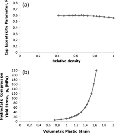
Fig. 10. (a) Cap eccentricity parameter R; (b) hydrostatic compression yield stress pb.
powders, and recently by Han et al.[14]. The friction coefficient μ was calculated as:
μ ¼ ln σlow=σupp
! "
=ð−4αH=DÞ ð13Þ
where D and H are the diameter of the die and the height of the pow-der in the die respectively. σupprepresents the upper punch stress, σlowthe lower punch stress and α the radial–axial transfer ratio. 3. Results
3.1. Cohesion and angle of internal friction
We used diametral and uniaxial compression tests to identify the cohesion and the internal friction. The obtained results are presented inFig. 8; the denser tablet has a higher strength. The evolutions of co-hesion and friction angle are shown inFig. 9. These results are similar to results obtained by Han et al.[14]for MCC Avicel PH101 having similar properties (mean particle size and true density) as MCC Vivapur 102. The results of the friction angle are rare and sometimes contradictory in literature. Stanley et al.[26]estimated the angle of internal friction of titanium dioxide using a shear cell. His results show that with increasing pressure, friction angle decreases.
Nevertheless, another result of Sinka et al. [27]shows rather a growth of the angle of internal friction and an exponential evolution of cohesion. However, our results are similar to those obtained by Han et al.[14]for Avicel PH101. Recently, Diarra et al.[28]obtained results comparable to ours for a cosmetic powder.
3.2. Parameters for defining cap surface
The parameters to define the cap surface are the eccentricity R and the hardening function pb. These parameters are determined from the stress strain curve during compression of the powder and the resolu-tion of Eq.(10)introduced before. The hardening behaviour in the
Fig. 12. Friction coefficient μ plotted as function of relative density.
Fig. 13. Finite element model of die compaction using flat-face punches.
Fig. 14. Finite element model of die compaction using concave face punches R20.
model and the variation of the relative density are defined in terms of the volumetric plastic strain:
εpv¼ ln ρ=ρð 0Þ ð14Þ
where ρ is the current relative density, and ρ0is the initial relative density on filling of die. The eccentricity R is approximately constant (little variation between 0.557 and 0.613) (Fig. 10a).Fig. 10b shows an increasing of the compression yield stress pbwith the volumetric plastic strain. The trends are comparable with those published in the literature. Recently, Diarra et al. found similar trend of R and pb
[28]. Han et al. found the same trend for pb, but the eccentricity R in-creases with relative density[14].
3.3. Young's modulus
Fig. 11shows the evolution of Young's modulus E obtained by uniax-ial compression plotted as function of relative density. There is a grow-ing trend of Young's modulus with densification of tablets. These results are similar to results obtained by Han et al.[14]for MCC Avicel PH101, for low stresses (b105 MPa).
3.4. Powder-die wall friction
The friction coefficient was determined using the approach de-scribed before.
The result is presented inFig. 12for MCC Vivapur 102 (unlubricated powder). This result is comparable to those found in the literature
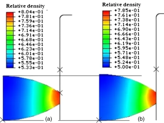
Fig. 16. Density distribution of powder compacted by flat-face punches: (a) at maximum compaction; (b) after decompression.
[2,9,14,27]. As shown inFig. 12, the friction coefficient decreases in the first stage of densification (relative density b 0.55), and tends towards an asymptotic value approximately equal to 0.4. As a comparison, Sinka et al. found a value around 0.5 for microcrystalline cellulose with-out lubrication[27]. Han et al. found a value around 0.21 for MCC Avicel PH101[14]. For the simulation, a mean constant value of 0.4 was taken. 3.5. Finite element simulation
The commercial software Abaqus® (Simulia) was used to simulate the uniaxial single-ended die compaction process of MCC Vivapur® powder. In this simulation, we used the visual Fortran compiler to
implement subroutine. The user subroutine (USDFLD) enabled to up-date the elastic parameters and the parameters of the failure curves when the relative density changed. The powder was modelled as a deformable continuum, while the punches and die were modelled as analytical rigid bodies without any deformation. The wall friction effect was considered by adopting a Coulombic boundary condition on the interfaces powder/wall and powder/punch. A constant friction coefficient equal to 0.4 was taken.
The numerical simulations correspond to three different geometries. A first case with flat-face punches and two concave face punches scored R10 and R20 having a certain curvature. The curvatures of punches R10 and R20 are arcs of circles with radius 10 mm and 20 mm respectively.
Fig. 18. Density distribution of powder compacted by concave-face R10 punches: (a) at maximum compaction; (b) after decompression.
Due to the axial symmetry, half of the powder bed was meshed with el-ements of type “CAX4R” four-node axisymmetric elel-ements as plotted in
Fig. 13for flat-face punches,Figs. 14 and 15for concave face punches. One of the ideas that we want to investigate is to understand how the applied load, on the flat and curved punches, will be transmitted to the powder during the compaction. For the comparison of the effect of the three shapes on the density distribution, the same dis-placement of 7 mm was assumed in the simulation. At the end of compaction, the height of the flat tablet is 3 mm, which corresponds to 0.8 of the relative density.
The model was validated, by observing a good agreement between finite element prediction and experimental measurement of loading and unloading curves, and by a comparison between predicted density distribution and experimental axial density presented in[10].
In the three cases, numerical simulation produces a gradient of density distribution throughout the height of the tablet. This hetero-geneity of the density distribution is principally owed to the friction imposed between tools and powder. So, the load of compression im-posed by the upper punch is not completely transmitted within the tablet. These results are similar to those obtained by Aydin et al.[20]
and Michrafy et al.[21]in sense where the upper edges are the densest
and the lower edges are the least dense. Also, similar results are ob-tained by Han et al.[14] for MCC powder and recently by Diarra et al. [28]for cosmetic powder. The friction prevents the powder from sliding along the interfaces of punches and die. As a result, very dense regions are developed on the upper edges of the tablet. During decompression, we can see an elastic relaxation and a decrease of rel-ative density (Fig. 16b).
Figs. 17 and 18show the density distribution at maximum com-paction using flat-face punches, the upper edges are the densest in the case of concave-face punches. But, we have a less dense core near to the symmetry axis. This result is qualitatively similar to X-ray tomography measurements obtained by Sinka et al.[27]. We also note that with decreasing the punch depth, the least dense zone at the lower edges increases. Furthermore, the important densification in the upper edges is owed to the maximum values of axial stress. The upper punch and the die are subjected on the upper edges to repeated stresses, which lead to a localized attrition or to shipping of punch coating, and decrease their shelf life. This shelf life is strongly reduced by the powder stick on the punch head.
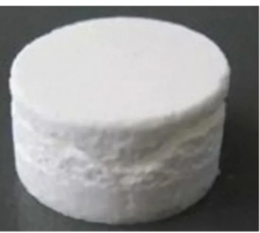
For flat-face punches, the stress distributions after decompression and during ejection are illustrated inFig. 19. The Von Mises stress dis-tribution introduces a contour of maximum shearing in about 45°. If the powder has a tendency to capping, it is in these areas where the crack initiation is possible. We can see inFig. 20a tablet of lac-tose with capping at approximately 45°. For concave face punches (Figs. 21 and 22), we see that the maximum values of Von Mises stresses are in the upper edges of the tablet. On the contrary, the min-imal values are close of symmetry axis. We note that there is an effect of the punch form on the stress distribution in the tablet. Indeed, as the punch depth increases, Von Mises stress increases. The stress dis-tribution changes during ejection where a part of the tablet is free to dilate and a part is compelled by the die wall. This situation could fa-cilitate cracks propagation and capping after ejection.
The obtained results in this study are in general agreement with the results of[13,29]. Indeed, whether for lactose powder or cellulose powder, the DPC model predicts a shear band at 45° indicating a po-tential capping (as a conical shape) in the middle of the compact. This explains two things: (i) the presented simulations in various works
Fig. 20. Capping of a tablet of lactose after ejection.
(including ours) cannot differentiate a plastic powder (cellulose) from fragmentary one (lactose), (ii) for some powders such as calcium carbonate CaCO3, more localized bands may occur (Fig. 23) and cannot be predicted by these simulations. Significant progress in improving these predictions should be developed.
4. Conclusions
The simulation of the compaction powder process allowed to re-produce the density and the stress distribution into the tablet and to calculate maximum efforts during compaction process. The obtained results show heterogeneity of the density distribution and the stresses in the tablet. Density distribution in the tablet is a result of the stress transmission that depends on the internal friction, as well as boundary conditions, contact powder/tools and lubrication. The heterogeneity of the density distribution has effects on mechanical resistance of the tablet and on its use properties. Indeed, the less dense parts are
subjected to damaging during manipulations, transport, or stocking and can have fast dissolution also. Moreover, this heterogeneity con-tinues developing during the decompression and the ejection phases. During decompression, the tablet could be subjected to an elastic relaxation which would lead to its capping. The tablet is subjected to stresses in tension, which can separate interparticle surfaces. More-over, in all cases, obtained results show very dense regions with strong shear stresses on the upper edges where the tablet may have a tendency to capping or crack initiation during decompression and ejection.
There is also an effect of the punch form on the density and stress distributions.
A powder that behaves well with a flat-face punches, may lead to non-compliant tablet with other shape of punches. However, these simulations are insufficient to predict the capping phenomenon. De-velopment efforts are required to improve their predictions. References
[1] M. Kottke, E. Rudnic, Tablet dosage form, Modern Pharmaceutics, 2002, pp. 287–333 (New York).
[2] A. Michrafy, M. Kadiri, J. Dodds, Wall friction and its effects on the density distri-bution in the compaction of pharmaceutical excipients, Transactions of the Insti-tution of Chemical Engineers 81 (2003) 946–952.
[3] A. Michrafy, S. Haas, M.S. Kadiri, K. Sommer, J. Dodds, The effects of ambient tem-perature on the compaction of pharmaceutical powders, Proceedings of the Insti-tution of Mechanical Engineers, Part E: Journal of Process Mechanical Engineering 220 (2006) 1–6.
[4] D. Drucker, R. Gibson, D. Henkel, Soil mechanics and work hardening theories of plas-ticity, Transactions of the American Society of Civil Engineers 122 (1957) 338–346. [5] A. Schofield, C. Wroth, Critical State Soil Mechanics, McGraw-Hill, London, 1968. [6] F.D. Maggio, I. Sandler, Material model for granular soils, Journal of Engineering
Mechanics (1971) 935–950.
[7] A. Gurson, Continuum theory of ductile rupture by void nucleation and growth: part I—yield criteria and flow rules for porous ductile media, Journal of Engineer-ing Material Technology (Transactions ASME) (1977) 2–15.
[8] R. Green, A plasticity theory for porous solids, International Journal of Mechanical Sciences 14 (1972) 215–224.
[9] M.S. Kadiri, Compression de poudres pharmaceutiques et interaction avec l'outillage, Ph.D. thesis, Institut National Polytechnique de Toulouse, France, 2004. Fig. 22. Stress distribution of powders compacted by concave-face punches R10: (a) after decompression; (b) during ejection.
[10] M.S. Kadiri, A. Michrafy, J. Dodds, Pharmaceutical powders compaction: experi-mental and numerical analysis of the density distribution, Powder Technology 157 (2005) 176–182.
[11] J. Cunningham, I. Sinka, A. Zavaliangos, Analysis of tablet compaction. I. Charac-terization of mechanical behavior of powder and powder/tooling friction, Journal of Pharmaceutical Sciences 93 (8) (2004) 2022–2039.
[12] C.-Y. Wu, O.M. Ruddy, A.C. Bentham, B.C. Hancock, S.M. Best, J.A. Elliott, Modelling the mechanical behaviour of pharmaceutical powders during compaction, Pow-der Technology 152 (2005) 107–117.
[13] G. Frenning, Analysis of pharmaceutical powder compaction using multiplicative hyperelasto-plastic theory, Powder Technology 172 (2007) 103–112.
[14] L. Han, J. Elliott, A. Bentham, A. Mills, G. Amidon, B. Hancock, A modified Drucker– Prager cap model for die compaction simulation of pharmaceutical powders, In-ternational Journal of Solids and Structures 45 (2008) 3088–3106.
[15] T. Sinha, J. Curtis, B. Hancock, C. Wassgren, A study on the sensitivity of Drucker Prager cap model parameters during the decompression phase of powder com-paction simulations, Powder Technology 198 (2010) 315–324.
[16] T. Sinha, R. Bharadwaj, J. Curtis, B. Hancock, C. Wassgren, Finite element analysis of pharmaceutical tablet compaction using a density dependent material plastic-ity model, Powder Technology 202 (2010) 46–54.
[17] A.T. Procopio, A. Zavaliangos, J.C. Cunningham, Analysis of the diametrical com-pression test and the applicability to plastically deforming materials, Journal of Materials Science 38 (2003) 3629–3639.
[18] S.P. Timoshenko, J.N. Goodier, Theory of Elasticity, 3rd ed. McGraw-Hill, New York, 1970.
[19] G. Hondros, The evaluation of Poisson's ratio and the modulus materials of a low tensile resistance by the Brazilian (indirect tensile) test with particular reference to concrete, Australian Journal of Applied Science 10 (3) (1959) 243–268.
[20] I. Aydin, B. Briscoe, K. Sanliturk, The internal form of compacted ceramic compo-nents: a comparison of a finite element modelling with experiment, Powder Technology 89 (1996) 239–254.
[21] A. Michrafy, D. Ringenbacher, P. Tchoreloff, Modelling the compaction behaviour of powders: application to pharmaceutical powders, Powder Technology 127 (3) (2002) 257–266.
[22] W.M. Long, Radial pressures in powder compaction, Powder Metallurgy 6 (1960) 73–86.
[23] W.M. Long, Die design and related questions in powder compaction, 2nd Sympo-sium of Special Ceramics, 1962, pp. 327–340.
[24] M. Es-Saheb, Uni-axial strain rate effects in pharmaceutical powders during cold compaction, Journal of Materials Science 27 (1992) 4151–4159.
[25] R.M. Nedderman, Statics and Kinematics of Granular Materials, Cambridge Uni-versity Press, New York, 1992.
[26] N. Stanley-Wood, M. Sarrafi, Variations in, and relationships of surface area, inter-nal angle of friction and compact diametral fracture strength with degree of com-paction, Particle and Particle Systems Characterization 5 (4) (1988) 186–192. [27] I. Sinka, J. Cunningham, A. Zavaliangos, The effect of wall friction in the
compac-tion of pharmaceutical tablets with curved faces: a validacompac-tion study of the Drucker–Prager cap model, Powder Technology 133 (2003) 33–43.
[28] H. Diarra, V. Mazel, A. Boillon, L. Rehault, V. Busignies, S. Bureau, P. Tchoreloff, Fi-nite element method (fem) modeling of the powder compaction of cosmetic products: comparison between simulated and experimental results, Powder Technology 224 (July 2012) 233–240.
[29] C.-Y. Wu, B.C. Hancock, A. Mills, A.C. Bentham, S.M. Best, J.A. Elliott, Numerical and experimental investigation of capping mechanisms during pharmaceutical tablet compaction, Powder Technology 181 (2008) 121–129.