Detection Of Static Eccentricity Fault In Saturated Induction Motors By Air-gap Magnetic Flux Signature Analysis Using Finite Element Method
16
0
0
Texte intégral
(2) N. Halem et al.. J. Fundam Appl Sci. 2013, 5(1), 53-68. 54. In the ideal case the stator and rotor have the same geometric axis (fig. 1a), in the case of static eccentricity the rotor rotates around its own geometric axis (fig. 1b), which is not the geometric axis of the stator, in case of dynamic eccentricity (fig. 1c); the rotor is not concentric and rotates around the geometric axis of the stator [3]. However even in new machines eccentricity usually occurs due to the build-up of tolerances during manufacturing stage [6].. Cr. Cr Cs=Cr. Cs. Cs. (a). (b). (c). Fig. 1. Types of eccentricity faults, (a) concentric rotor, (b) static eccentricity, (c) dynamic eccentricity In induction motors the majority of faults are connected to the mechanical and rotor faults, while 80% of mechanical faults result in eccentricity [7]-[8]. The detection of incipient eccentricity faults in induction motors is one of the most important objectives in the maintenance of industrial systems. Traditionally the Motor Current Signature Analysis (MCSA) is used to diagnose all of the trouble types in induction motors. The initial work in the detection of eccentricity taking account rotor slot related formulas using MCSA and vibration was done by Cameron [9], since there many research works head to detect the eccentricity fault in induction motor using MCSA [10]-[11]-[12]. By another eye, several research works affirmed that MCSA has a limited usability to detect faults in induction motor especially in some cases. Usually MCSA is used to detect a high levels of both eccentricity types, it mean when the static and dynamic eccentricity exist together, but it is very difficult to detect such faults if they appear individually [13]-[5], for those authors the fault signatures are presented in stator current spectrum only if the two kinds of eccentricity exist together and it is not easy to distinguish them. In addition, it will be difficult to diagnose the low level static eccentricity with traditional MCSA technique, for them other signals such as noise, bearing vibration and temperature may have to be used in these cases for detecting fault signature [3]. For Concari et al, diagnostic procedures based only on sideband current components may fail in some.
(3) N. Halem et al.. J. Fundam Appl Sci. 2013, 5(1), 53-68. 55. cases for them other induction motor quantities help to detect signatures produced by the different faults such as stray flux and vibrations [14]. Many research works head to use others induction motor quantities to detect SE fault signatures such air gap magnetic flux density [13]-[15], terminal voltages of induction machines at switch-off [5]. Magnetic saturation phenomena is an invariant parameter induction motors, several work research investigate that the magnetic saturation is necessary to study and analyze induction motor suffered from eccentricity fault [16]-[7], while most of induction motor models neglected it. In spite of its inconveniences of a long time of calculation and a need of powerful computers, the power and versatility of the FEM are by now well known and have led to rapid growth in its use. FEM is able to closer the reality and extend accurate results, also unlike other methods FEM offers a high space harmonics of induction motor which open a restful way to diagnose and study the induction motor using signature analysis. The air gap magnetic field contains full information of the stator condition and mechanical parts of the induction motor, the Fast Fourier Transform (FFT) application to air gap magnetic flux density is used to detect different fault in induction motors, the approach is known as flux signature analysis (FSA). The usability of analysis of external magnetic field to detect faults in induction motor have proved by several papers, the majority of those papers are interested on diagnosis of broken rotor bar [17]-[18]-[14]-[15], stator winding short-circuits [19, 20], net voltage asymmetry [21] wound rotor phase disconnection [22], dynamic eccentricity [13]. This paper heads to diagnose low levels of purely SE in induction motor using TSFE method, short description of this technique modeling will be presented in first part of paper. The application of FSA to detect purely SE in induction motor for constant and non linear permeability is included in the second part of paper.. 2.. MODELLING OF INDUCTION MOTOR USING TSFE METHOD. In 1988 the Time Stepping Finite Element (TSFE) technique proposed by researchers of GEC research center [23, 24]. Several authors head to the application of this technique for studying and analyzing eccentricity fault in induction motors [10], for them the assumption that currents and fluxes are sinusoidal varying restrict the solution if information such as stator current harmonics and torque pulsation are required, the alternative would be the full timestepping. Several papers have been used TSFE method to diagnose different faults in induction motors, most of these papers are focused on the diagnosis of broken rotor bar [25][26-28], in case of eccentricity analysis [10, 29, 30], in case of stator winding turn fault [31]..
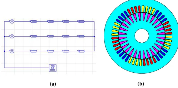
(4) N. Halem et al.. J. Fundam Appl Sci. 2013, 5(1), 53-68. 56. TSFE analysis of induction motor based circuit-coupled method Generally the induction motor is excited by an external voltage source, from many models based on finite elements method, only the Circuit-Coupled Finite Element Method (CircuitCoupled FEM) can close this reality, here the external electric circuit which contains the three voltage sources is coupled to the finite element domain which contains the magnetic circuit of the electric machine (fig. 2) [32]-[28]. In table 1, specifications of the studied induction motor.. (b). (a). Fig. 2. Circuit coupled FEM mode: a electric circuit; b magnetic circuit. Flux density (T). 2 1.5 1 0.5 0. 0. 2000 4000 6000 8000 Magnetic field strength (A/m). 10000. Fig. 3. Magnetization characteristic of core. An initial iron relative permeability of 1000 is assigned to the laminated iron core. For a comparison the calculation are also done for a saturated ferromagnetic material for which the laminated iron region is modeled by a B-H curve (fig. 3)..
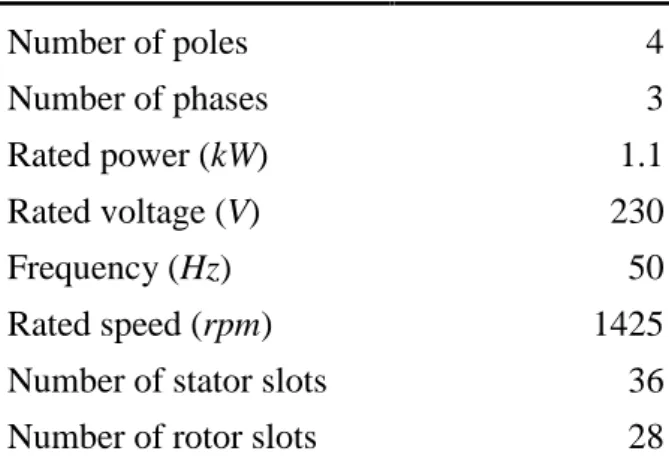
(5) N. Halem et al.. J. Fundam Appl Sci. 2013, 5(1), 53-68. 57. Table 1. Specifications of studied induction motor Number of poles. 4. Number of phases. 3. Rated power (kW). 1.1. Rated voltage (V). 230. Frequency (Hz) Rated speed (rpm). 50 1425. Number of stator slots. 36. Number of rotor slots. 28. For Preston [23] the transient magnetic field in terms of magnetic vector potential A , the reluctivity, conductivity , and current density J can be expressed as:. A A A J x x y y t. (1). The last term represents current induced in conducting material when flux changes with time. For Salon [33] and Lombard [34] the full transient performance can be obtained by accounting for the mechanical equation of the motor and the transient motional induced eddy current in the rotor bars can't be neglected as in equation (1), the complete system is based on the differential equation in compact form: A A E V A t . (2). Where V is the speed of the moving parts, E is the electrical scalar potential applied by the external circuit. So the problem is considered as transient alike. When the motor is loaded the voltage time step must be accompanied by rotor motion corresponding to the slip. The method is direct one if the iron nonlinearity is incorporated in the transient analysis and the external voltage sources are implied within the system of finite element set of simultaneous equation. Static eccentricity fault diagnosis using air gap magnetic flux density signature analysis In this paper the induction motor under low levels of purely SE (5 and 10 %) is modeled with high precision using TSFE method. In the finite element model the geometry of induction motor has two different centers; stator and rotor centers. Ideally the two centers are placed at the same position, so the air gap is symmetrical, by shifting the rotor center away from the.
(6) N. Halem et al.. J. Fundam Appl Sci. 2013, 5(1), 53-68. 58. stator center the space-fixed minimum air gap will be formed, this technique is used to model the SE in induction motor. Frequencies given by the following relationship:. 1 s f f h kR nd s p . (3). are used to detect eccentricity-related fault signatures in the stator current, the vibrationrelated spectrum and air gap magnetic flux density. Here nd 0 in case of static eccentricity,. nd 1, 2,3,... in case of dynamic eccentricity ( nd is known as eccentricity order), f s is the fundamental supply frequency, R is the number of rotor slots, s is the slip, p is the number of pole pairs, k is any integer and is the order of the stator time harmonics that are present in the power supply driving the motor 1, 3, 5,.... [5]. It was shown that some of research works leaned on the amplitude variations and the appearing of new components around which called principal slot harmonics (PSHs) to diagnose the eccentricity fault in induction motor [35]. PSHs are given by the following relationships [36]: The lower (first) principal harmonic:. R f PSH 1 f s 1 1 s p . (4). The upper (second) principal harmonic:. R f PSH 2 f s 1 1 s p . (5). Obviously, the frequencies given by (4) and (5) depend on machine load, by other words; position of PSHs in stator current spectrum depends on rotor speed. However, the existence of PSHs in current line spectrum depends on the number of pole pairs and rotor slots which lead that the detection of eccentricity fault in stator current spectrum around the PSHs is effective only for some combination of number of pole pairs and rotor slots. As will be shown, for modeled induction motor, both PSHs exist in stator current and air gap magnetic flux density spectrums. More details of combination of number of pole pairs-rotor slots are presented in [5]-[38]-[37]-[36]. However for all machines static and dynamic eccentricity-related components result around the fundamental harmonic is given by [5]:. f ecc f s k f r. (6).
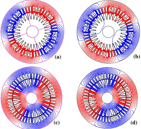
(7) N. Halem et al.. J. Fundam Appl Sci. 2013, 5(1), 53-68. 1 s f. fr . p. 59. (7). s. Where k 1, 2,3,... Figure 4a, b, c presents the magnetic flux distribution, the flux line maps are taken from healthy and faulty saturated induction motor under 10% of SE at starting operation and steady state operation it can be observed that when static eccentricity occurs, the magnetic flux distribution is deformed.. Isovalues Results Quantity : Equi flux Weber. Is o v a lu e s R e s u lts Quant i t y : Equi f l ux Weber Ti m e ( s. ) : 400E- 6 Pos ( deg) : - 1, 738E- 3 Li ne / Val ue 1 / - 141, 9593E- 6 2 / - 131, 03934E- 6 3 / - 120, 11938E- 6 4 / - 109, 19942E- 6 5 / - 98, 27946E- 6 6 / - 87, 35951E- 6 7 / - 76, 43954E- 6 8 / - 65, 51958E- 6 9 / - 54, 59963E- 6 10 / - 43, 67967E- 6 11 / - 32, 75971E- 6 12 / - 21, 83975E- 6 13 / - 10, 91979E- 6 14 / 0 15 / 10, 92013E- 6 16 / 21, 84009E- 6 17 / 32, 76004E- 6 18 / 43, 6791E- 6 19 / 54, 59996E- 6 20 / 65, 51992E- 6 21 / 76, 43988E- 6 22 / 87, 35984E- 6 23 / 98, 27979E- 6 24 / 109, 19975E- 6 25 / 120, 11972E- 6 26 / 131, 03968E- 6 27 / 141, 95964E- 6. (b). (a). Time (s.) : 400E-6 Pos (deg): -1,738E-3 Line / Value 1 / -148,75917E-6 2 / -137,43452E-6 3 / -126,10988E-6 4 / -114,78523E-6 5 / -103,46059E-6 6 / -92,13595E-6 7 / -80,81131E-6 8 / -69,48667E-6 9 / -58,16202E-6 10 / -46,83738E-6 11 / -35,51274E-6 12 / -24,1881E-6 13 / -12,86346E-6 14 / -1,53881E-6 15 / 9,78583E-6 16 / 21,11047E-6 17 / 32,43511E-6 18 / 43,75975E-6 19 / 55,08439E-6 20 / 66,40904E-6 21 / 77,73368E-6 22 / 89,05832E-6 23 / 100,38296E-6 24 / 111,7076E-6 25 / 123,03225E-6 26 / 134,35689E-6 27 / 145,68154E-6. Isovalues Results Quantity : Equi flux Weber Is o v a lu e s R e s u lts Quant i t y : Equi f l ux Weber Ti m e ( s. ) : 4 Pos ( deg) : 33, 579E3 Li ne / Val ue 1 / - 1, 06158E- 3 2 / - 979, 91631E- 6 3 / - 898, 25114E- 6 4 / - 816, 58596E- 6 5 / - 734, 92079E- 6 6 / - 653, 25556E- 6 7 / - 571, 59038E- 6 8 / - 489, 92515E- 6 9 / - 408, 25998E- 6 10 / - 326, 59477E- 6 11 / - 244, 92957E- 6 12 / - 163, 26438E- 6 13 / - 81, 59919E- 6 14 / 0 15 / 81, 7312E- 6 16 / 163, 3964E- 6 17 / 245, 06159E- 6 18 / 326, 72679E- 6 19 / 408, 39199E- 6 20 / 490, 05717E- 6 21 / 571, 7224E- 6 22 / 653, 38757E- 6 23 / 735, 0528E- 6 24 / 816, 71798E- 6 25 / 898, 38315E- 6 26 / 980, 04832E- 6 27 / 1, 06171E- 3. (c). (d). Time (s.) : 4 Pos (deg): 33,588E3 Line / Value 1 / -1,07347E-3 2 / -991,29917E-6 3 / -909,13166E-6 4 / -826,96415E-6 5 / -744,79665E-6 6 / -662,6292E-6 7 / -580,4617E-6 8 / -498,29419E-6 9 / -416,12668E-6 10 / -333,95921E-6 11 / -251,7917E-6 12 / -169,62421E-6 13 / -87,45671E-6 14 / -5,28921E-6 15 / 76,87828E-6 16 / 159,04578E-6 17 / 241,21327E-6 18 / 323,38078E-6 19 / 405,54826E-6 20 / 487,71576E-6 21 / 569,88327E-6 22 / 652,05077E-6 23 / 734,21822E-6 24 / 816,38573E-6 25 / 898,55323E-6 26 / 980,72074E-6 27 / 1,06289E-3. Fig. 4. Flux lines distribution: a starting operation of healthy motor; b starting operation of faulty motor with 10% SE; c steady state operation of healthy motor; d steady state operation of faulty motor with 10% SE.
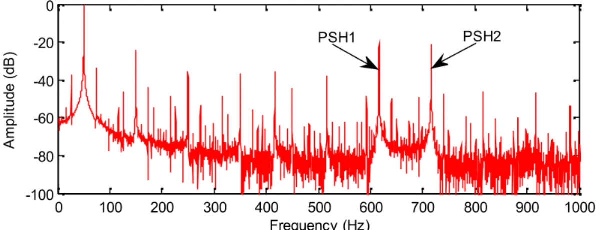
(8) N. Halem et al.. J. Fundam Appl Sci. 2013, 5(1), 53-68. 60. Radial induction (T). 1.5 1 0.5 0 -0.5 -1 -1.5. 0. 90. 180 Angle (degree). 270. 360. 270. 360. 270. 360. (a). Radial induction (T). 1.5 1 0.5 0 -0.5 -1 -1.5. 0. 90. 180 Angle (degree). (b). Radial induction (T). 1.5 1 0.5 0 -0.5 -1 -1.5. 0. 90. 180 Angle (degree). (c) Fig. 5. Radial induction distribution in induction motor air gap with non-linear magnetization characteristic: a healthy at full-load; b with 10% SE at full-load; c with 10% SE at no-load Spectrum analysis of air gap magnetic flux density of healthy and faulty motor Figure 6, presents the air gap flux density spectrums for full-load healthy induction motor under non-linear permeability, it can clearly shown that the PSH1 and PSH2 occur.
(9) N. Halem et al.. respectively at. J. Fundam Appl Sci. 2013, 5(1), 53-68. 1 0.048 / 2 28 1 50 Hz 616.4 Hz. 61. and 716.4 Hz, also the air gap magnetic. flux density spectrum under saturated motor is very rich by the expectation harmonic components, such saturation harmonics and saturation related harmonics. Figure 7 shows the air gap magnetic flux density spectrum for full-load faulty induction motor under non-linear permeability, the index signatures of SE fault are successfully appeared around fundamental harmonic and PSHs.. Amplitude (dB). 0 PSH2. PSH1. -20 -40 -60 -80 -100. 0. 100. 200. 300. 400 500 600 Frequency (Hz). 700. 800. 900. 1000. Fig. 6. Air gap magnetic flux density spectrum for full-load healthy induction motor under non-linear permeability. Amplitude (dB). 0 PSH2. PSH1. -20 -40 -60 -80 -100. 0. 100. 200. 300. 400 500 600 Frequency (Hz). 700. 800. 900. 1000. Fig. 7. Air gap magnetic flux density spectrum for full-load faulty induction motor with 10% SE under non-linear permeability Static eccentricity index signatures around fundamental harmonic Figure 8a, b, c shows the spectrums of the air gap magnetic flux density around fundamental harmonic of healthy and faulty saturated induction motor. It can clearly observed that the components at frequency f s kf r are successfully appeared. For k 1 , the specific fault harmonics occur at f s f r 26.2 Hz and 73.8Hz . As shown in fig. 7b with 5% of SE and fig..
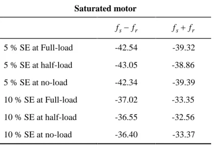
(10) N. Halem et al.. J. Fundam Appl Sci. 2013, 5(1), 53-68. 62. 7c with 10% of SE, the amplitude of low side-band component at frequency f s f r increases from -42.54dB to -37.02dB, also the amplitude of upper-side-band component at frequency. f s f r increases from -39.32dB to -33.35dB. Also as shown in fig. 7c the severity of SE fault. Amplitude (dB). with 10% leads to generate the side-band component frequency at f s 2 f r 97.6 Hz . 0 -20 -40 -60 -80. 0. 25. 50 Frequency (Hz). 75. 100. Amplitude (dB). (a). 0 fs -fr. -20. fs +fr. -40 -60 -80. 0. 25. 50 Frequency (Hz). 75. 100. Amplitude (dB). (b). 0 fs -fr. -20. fs +fr. -40. fs +2fr. -60 -80. 0. 25. 50 Frequency (Hz). 75. 100. (c). Fig. 8. Zoom around fundamental harmonic of the air gap magnetic flux density spectrum at full-load saturated motor: a healthy motor; b with 5% of SE; c with 10% of SE.
(11) N. Halem et al.. J. Fundam Appl Sci. 2013, 5(1), 53-68. 63. Table 2. Amplitude of side-band components around fundamental harmonic for 5% and 10% of SE and different loads in dB Saturated motor. fs fr. fs fr. 5 % SE at Full-load. -42.54. -39.32. 5 % SE at half-load. -43.05. -38.86. 5 % SE at no-load. -42.34. -39.39. 10 % SE at Full-load. -37.02. -33.35. 10 % SE at half-load. -36.55. -32.56. 10 % SE at no-load. -36.40. -33.37. Static eccentricity index signatures around PSHs In addition of SE fault index signatures around fundamental harmonic, fig. 9a, b, c presents the frequency spectrums of the air gap magnetic flux density around PSHs for saturated healthy and faulty induction motor, which indicate the sensibility of the air gap magnetic flux density and its high ability to detect a low levels of SE fault. 0. Amplitude (dB). -20. PSH2. PSH1. -40 -60 -80 -100 550. 600. 650 Frequency (Hz). (a). 700. 750.
(12) N. Halem et al.. J. Fundam Appl Sci. 2013, 5(1), 53-68. 64. 0. Amplitude (dB). -20 -40. fs -(R+1)fr. fs -(R-1)fr. fs +(R-1)fr. fs +(R+1)fr. -60 -80 -100 550. 600. -20 -40. 650 Frequency (Hz). 700. 750. (b). 0. Amplitude (dB). PSH2. PSH1. PSH2. PSH1 fs -(R+1)fr. fs -(R-1)fr. fs +(R-1)fr. fs +(R+1)fr. -60 -80 -100 550. 600. 650 Frequency (Hz). 700. 750. (c) Fig. 9. Zoom around fundamental harmonic of the air gap magnetic flux density spectrum at full-load, saturated motor: a healthy motor; b with 5% of SE; c with 10% of SE.. For full-load motor the frequency components around PSH1 occur at. f s R 1 f r 592.6 Hz and 640.2Hz , while the frequency components around PSH2 occur at f s R 1 f r 692.6 Hz and 740.2Hz . Table 3 summarize the amplitudes and frequencies of components around PSHs. The clearly observation that the amplitudes of sideband components increase when the degree of SE fault doubled..
(13) N. Halem et al.. J. Fundam Appl Sci. 2013, 5(1), 53-68. 65. Table 3. Amplitude of side-band components around PSHs for 5% and 10% of SE at fullloaded motor in dB saturated motor Around PSH1. Around PSH2. f s R 1 f r. f s R 1 f r. f s R 1 f r. f s R 1 f r. 5 % SE. -55.02. -56.43. -55.44. -53.84. 10 % SE. -48.54. -49.60. -48.90. -47.20. 3. CONCLUSION In this paper, a highly precise modeling TSFE method is used to diagnose low levels of purely SE fault in three phase saturated induction motor. The failure of MCSA to detect the index frequencies of purely SE is successfully replaced by the efficiency and sensibility of the air gap magnetic flux density signature analysis, where the basic known index of SE around fundamental and PSHs were appeared very clearly even under very small degree of SE.. 4. REFERENCES [1] Arkkio A and Lindgren O, 1994. Unbalanced magnetic pull in a high speed induction motor with an eccentric rotor. ICEM, Paris, France: 53-58. [2] Tenhunen A, 2001. Finite-element calculation of unbalanced magnetic pull and circulating current between parallel windings in induction motor with non-uniform eccentric rotor. Proc, Electromotion, Bologna, Italy: 19-24. [3] Li X., Wu Q., Nandi S, 2007. Performance analysis of three-phase induction machine with inclined static eccentricity. IEEE Trans Ind App 43(2): 531-541. [4] Dorell D. G, 2011. Sources and characteristics of unbalanced magnetic pull in three-phase cage induction motor with axial-varying rotor eccentricity. IEEE Trans Ind Appl 47(1): 12-24. [5] Nandi S., Ilamparithi T. C., Lee S. B., Hyun D, 2011. Detection of eccentricity faults in induction machines based on nameplate parameters. IEEE Trans Ind Appl 58(5): 1673-1683. [6] Dorell D. G., Thomson W. T., Roach S, 1997. Analysis of air-gap flux, current, vibration signals as a function of the combination of static and dynamic air-gap eccentricity in 3-phase induction motors. IEEE Trans Ind Appl 33(1): 24-34..
(14) N. Halem et al.. J. Fundam Appl Sci. 2013, 5(1), 53-68. 66. [7] Faiz J., Ebrahimi B. MToliyat H. A, 2009. Effect of magnetic saturation on static and mixed eccentricity fault diagnosis in induction motor. IEEE Trans Magnetics 45(8): 31373144. [8] Akar M, 2012. Detection of a static eccentricity fault in a closed induction motor by using the angular domain order tracking analysis method. Mechanical Systems and signals Processing 34 (2013): 173-182. [9] Cameron J. R., Thomson W. T., and. Dow A. B, 1986. Vibration and current monitoring for detecting air-gap eccentricity in large induction motors. Proc Inst Electr Eng 133(3): 155163. [10] Thomson W. T., Barbour A, 1998. On-line current monitoring and application of finite element method to predict the level of static airgap eccentricity in three-phase induction motors. IEEE Trans Energy Conversion 13(4): 347-357. [11] Benbouzid M. H., Kliman G. B., Fellow L, 2003. What stator current processing-based technique touse for induction motor rotor faults diagnosis. IEEE Trans Energy Conversion 18(2): 238-244. [12] Sahraoui M., Ghoggal A., Zouzou S. E., Benbouzid M.E, 2008. Dynamic eccentricity in squirrel cage induction motors –simulation and analytical study of its spectral signatures on stator currents. Simulation Modelling Practice and Theory 16(4): 1503-1513. [13] Vitek O., Janda M., Hajek V, 2010. Effects of eccentricity on external magnetic field of induction machine. Melecon 15th IEEE Mediterranean Electrotechnical conference 939-943. [14] Concari C., Franceschini G., Tassoni C, 2008. Differential diagnosis based on multivariable monitoring to assess induction machine rotor conditions. IEEE Trans industrial electronics 55(12): 4156-4166. [15] Ceban A., Pusca R., Romary R, 2012. Study of rotor faults in induction motors using external magnetic field analysis. IEEE Trans Ind Electronics 59(5): 2082-2093. [16] Nandi S, 2004. A detailed model of induction machines with saturation extendable for fault analysis. IEEE Trans Ind Appl 40(5): 1302-1309. [17] Belkhayat D., Romary R., El Adnani M., Corton R., Brudny J.F., 2003. Fault diagnosis in induction motors using radial field measurement with an antenna. Institute of Physics publishing London (UK) Meas Sci Technol 14(2003): 1695-1700. [18] Kia S. H., Henao H., Capolino G. H., Martis C, 2006. Induction machine broken bars fault detection using stray flux after supply disconnection. IEEE 32nd Annual Conference Ind Electronics 1498-1503..
(15) N. Halem et al.. J. Fundam Appl Sci. 2013, 5(1), 53-68. 67. [19] Henao H., Demian C., Capolino G. A, 2003. A frequency-domain detection of stator winding faults in induction machines using an external flux sensor. IEEE Trans Ind Appl 39(5): 1272-1279. [20] Yazidi A., Henao H., Capolino G.A., Artioli M., Filippetti F., Casadei D, 2007 Flux signature analysis: An alternative method for the fault diagnosis of induction machines. IEEE Power Tech Russia: 675-680. [21] Bacha K., Gossa M., Henao H., Capolino G. A, 2006. Comparative investigation of diagnosis media of stator voltage asymmetry and rotor broken bars in induction machines. IEEE 32nd Annual Conference on Ind Electronics: 5040-5045. [22] Ondel O., Yazidi A., Boutleux E., Clerc G., Henao H., Casimir R., Capolino G.A, 2004 Comparative study of two diagnosis methods induction machine. IEEE International Conference on Industrial Technology: 159-165. [23] Preston T. W., Reece A. B. J., Sangha P. S, 1988. Induction motor analysis by timestepping technique. IEEE Trans Magnetics 24(1): 471-474. [24] Sangha P. S, Preston T. W., Reece A. B. J, 1989. Design analysis by finite-element timestepping technique. Proc of IEE Forth Int Conf On Electrical Machines and Drives: 11-15. [25] Bangura F., Demerdash N. A, 1999. Performance and torque-ripple characterization in induction motor adjustable-speed drives using time-stepping coupled finite-element statespace techniques. IEEE Trans Ind Appl 35(5): 982-990. [26] Povinelli R. J., Bangura J. F., Demerdash N. A., Brown R. H, 2002. Diagnostics of bar and end-ring connector breakage faults in polyphase induction motors through a novel dual track of time-series data mining and time-stepping coupled finite element-state space modeling. IEEE Trans On Energy Conversion 17(1): 39-46. [27] Halem N., Zouzou S. E., Srairi K, 2011. Analysis of induction motor with broken bars and constant speed using circuit-coupled method. J. Fund. App. Sci., 2011, 3(2): 106-120. [28] Zouzou S. E., Khelif S., Halem N., Sahraoui M, 2011. Analysis of induction motor with broken rotor bars using circuit-field coupled method. International conference on electric power and Energy Conversion Systems, Sharjah, UAE: 15-17. [29] Bangura F., Demerdash N. A, 2000. Comparison between characterization and diagnosis of broken bars/end-ring connectors and airgap eccentricities of induction motor in ASD's using a coupled finite element-state space method. IEEE Trans On Energy Conversion 15(1): 48-56..
(16) N. Halem et al.. J. Fundam Appl Sci. 2013, 5(1), 53-68. 68. [30] Faiz J., Ebrahimi B. M., Akin B., Toliyat H. A, 2009. Comprehensive eccentricity fault diagnosis in induction motors using finite element method. IEEE Trans Magnetics 45(3): 1764-1767. [31] Vaseghi B., Takorabet N., Meibody-tabar F, 2009. Transient finite element analysis of induction machines with stator winding turn fault. Progress in electromagnetics research, PIER 95: 1-18. [32] Sadowski N., Carlson R., Arruda S. R., Silva C. A., Mazenc M. L, 1995. Simulation of single-phase induction motor by general method coupling field and circuit equations. IEEE Trans Magnetics 31(3): 1908-1911. [33] Salon S. J., Burow D. W., Ashly R. E., Ovacik L., DeBotoli M. J, 1993. Finite element analysis of induction machine in the frequency domain. IEEE Trans Magnetics 29(2): 14381441. [34] Lombard P., Meunier G, 1992. A general method for electric and magnetic coupled problem in 2D and magnetodynamic domain. IEEE Trans Magnetics 28(2): 1291-1294. [35] Faiz J., Ebrahimi B. M., Akin B., Toliyat H. A, 2010. Dynamic analysis of mixed eccentricity signatures at various operating points and scrutiny of related indices for induction motor. IET Electr. Power Appl 4(1): 1-16. [36] Joksimovic G., Riger J., Wolbank T., Peric N., Vasak M, 2011. Stator line current spectrum content of a healthy cage rotor induction machine. SDEMPED, Bologna, Italy. [37] Joksimovic G, 2010. Stator current harmonics in saturated cage and wound rotor induction motors. XIX international conference on electrical machines, ICEM 2010, Rome, Italy. [38] Joksimovic G, 2010. Line current spectrum analysis in saturated three-phase cage induction machine. Electrical Engineering, Springer Verlag, 91(8): 425-437.. How to cite this article Halem N, Zouzou S E, Srairi K, Guedidi S and Abood F A. Detection of static eccentricity fault in saturated induction motors by air-gap magnetic flux signature analysis using finite element method. J Fundam Appl Sci. 2013, 5(1), 53-68..
(17)
Figure

+7


Documents relatifs
Furthermore, analysis of the stator current was conducted in healthy cases and in the presence of defects, the second method of fault detection in this work,is based on
have proposed a new model for bearing fault detection using stator currents, which shows that such faults produce very small amplitude and frequency modulations of the stator
At the limit, when the estimated number of broken bars is null, the initial rotor position has no influence on the stator currents computed by the model as it has been stated
L’archive ouverte pluridisciplinaire HAL, est destinée au dépôt et à la diffusion de documents scientifiques de niveau recherche, publiés ou non, émanant des
This solution serves then as a source for a perturbation problem allowing leakage flux in the inner region of the core (Fig. 3, middle), followed by another problem allowing
In Section 4, the supremacy of the new observer over standard ones is illustrated by simulation, using the model developed and experimentally validated in (Ouadi et al, 2004a) for
4, where the chosen supply frequency creates a resonance between the exciting slotting force harmonic F slot 0 and the stator breathing mode number 0: main slotting lines are
Indeed, the air-gap flux density is locally inverted (or switched) over the coil phase leading to a bipolar flux-linkage. Even for configurations which are difficult to model, such
