To link to this article : DOI:10.1111/aor.12476
URL :
http://dx.doi.org/10.1111/aor.12476
To cite this version :
Macé, Marc and Denis, Grégoire and Jouffrais,
Christophe Simulated prosthetic vision: The benefits from
computer-based object recognition and localization. (2015) Artificial Organs,
vol. 39 (n° 7). pp. E102-E113. ISSN 0160-564X
O
pen
A
rchive
T
OULOUSE
A
rchive
O
uverte (
OATAO
)
OATAO is an open access repository that collects the work of Toulouse researchers and
makes it freely available over the web where possible.
This is an author-deposited version published in :
http://oatao.univ-toulouse.fr/
Eprints ID : 15215
Any correspondence concerning this service should be sent to the repository
administrator:
[email protected]
Simulated Prosthetic Vision: The Benefits of
Computer-Based Object Recognition and Localization
Marc J.-M. Macé, Valérian Guivarch, Grégoire Denis, and Christophe Jouffrais
CNRS & University of Toulouse, IRIT, Toulouse, France
Abstract: Clinical trials with blind patients implanted with
a visual neuroprosthesis showed that even the simplest tasks were difficult to perform with the limited vision restored with current implants. Simulated prosthetic vision (SPV) is a powerful tool to investigate the putative functions of the upcoming generations of visual neuro-prostheses. Recent studies based on SPV showed that several generations of implants will be required before usable vision is restored. However, none of these studies relied on advanced image processing. High-level image processing could significantly reduce the amount of infor-mation required to perform visual tasks and help restore visuomotor behaviors, even with current low-resolution implants. In this study, we simulated a prosthetic vision device based on object localization in the scene. We evalu-ated the usability of this device for object recognition,
localization, and reaching. We showed that a very low number of electrodes (e.g., nine) are sufficient to restore visually guided reaching movements with fair timing (10 s) and high accuracy. In addition, performance, both in terms of accuracy and speed, was comparable with 9 and 100 electrodes. Extraction of high level information (object recognition and localization) from video images could drastically enhance the usability of current visual neuroprosthesis. We suggest that this method—that is, localization of targets of interest in the scene—may restore various visuomotor behaviors. This method could prove functional on current low-resolution implants. The main limitation resides in the reliability of the vision algorithms, which are improving rapidly. Key Words:
Visual impairment—Blindness—Visual neuroprosthesis— Simulated prosthetic vision—Computer vision.
Among all the sensory deprivations, blindness is one of the most disabling in our society. Visual neuroprostheses, which combine a camera with a neural interface implanted over the retina or the visual cortex, have been proposed for quite a long time as a potential solution to restore sight (1–4). Electrical microstimulations of the visual system evoke visual percepts called phosphenes, even for early blind (3). These percepts are generally white-to-yellow round or oval shapes spread across the visual field, depending on the location of the stimulation.
Visual neuroprostheses have been developed for the retina, the optic nerve, and the visual cortex (5–8). Around the world, only a handful of
individu-als have been implanted with cortical or optic nerve array of electrodes and a few dozen received retinal implants, usually for a limited period of time. Based on the perceptual reports of this limited set of patients, general rules regarding the phenomenology of phosphenes have been established. Each electrode of an implanted array usually elicits one phosphene, but sometimes more than one or no phosphene at all depending on microstimulation location and inten-sity. A given electrode elicits a phosphene at a rela-tively fixed position across stimulation repetitions, and several electrodes may be simultaneously switched on to display a pattern of multiple phosphenes although phosphene fusion may occur on adjacent electrodes.
Relying on these basic rules of phosphene genera-tion, a classical method to restore vision, the so-called “scoreboard” (6) method, consists of estab-lishing a direct mapping of the visual information from the camera image onto the electrode array. Because the numbers of pixels in the image is usually much higher than the number of electrodes available
onto the array, a down-sampling is performed on the input images. This resampling is sometimes comple-mented with a simple edge detection filter to increase local contrasts on edges (9).
Because of the low numbers of implanted patients, less than a hundred around the world in 2014 (10), it is difficult to investigate functional recovery, and several research groups have developed simulated prosthetic vision (SPV) devices. The classical method relies on sighted subjects wearing a virtual reality (VR) helmet. The subject is deprived of normal viewing and only perceives phosphenes displayed in the VR helmet. A convenient advantage of simula-tion is that all the parameters of phosphene elicita-tion can be freely adjusted and tested. These parameters include the number, density, and position of the implanted electrodes, the dropout rate to simu-late nonfunctional electrodes, the apparent lumi-nance of the phosphenes, the methods for image conversion and filtering, etc. Despite large differ-ences between the simulation of prosthetic vision and actual neuroprosthesis, it is possible to approxi-mately define the minimal number of phosphenes required to perform different tasks.
When using the scoreboard method, the number of phosphenes, which depends on the number of electrodes, is critical for the usability of the neuroprosthesis. Several SPV studies aimed to define the minimal number of phosphenes necessary to perform various visual and visuomotor tasks. Reading isolated letters or spelling words becomes possible with a monocular array of 256 electrodes (16 × 16) subtending 1.5° (11). However, 625 phosphenes (25 × 25 grid covering 10 × 10°) provide much more comfort and increase the reading speed to acceptable levels (12). In mobility tasks, a grid of 25 × 25 phosphenes covering 30° of visual angle is sufficient to walk nearly at the same speed as sighted subjects while avoiding collisions with small obstacles (13). This resolution is, however, insufficient to per-ceive distant landmarks in navigation tasks. Object recognition becomes possible with 256 phosphenes in extremely constrained tasks with 4 different black objects and up to 3 min to identify each object (14). Subjects recognize and manipulate black figures with almost 500 phosphenes covering a visual field of 10 × 7° (15). More than 600 phosphenes are required in more open recognition tasks with a set of 20 objects (16,17). A face recognition task requires a minimum of 625 (25 × 25) to 1024 (32 × 32) phosphenes (18), whereas achieving a fair level of scene recognition requires more than 2000 phosphenes (17). This high number of phosphenes is a huge obstacle in the development of usable visual
prosthesis. Indeed, during the last 40 years, the number of electrodes available on implantable arrays has been restricted to a hundred at most (1,4,19). For photodiode-based subretinal implants, microelec-tronic techniques allow for the dense packing of active elements (1500 to 5000 photodiodes [20,21]), but these implants have not demonstrated functional superiority compared with 60 + electrodes in epiretinal implants (8,22), probably due to electrical crosstalk or sub-optimal electrode stimulation. For cortical or epiretinal implants, a higher number of electrodes has been advertised for a long time without effective results. Based on previous observa-tion on the pace of progress, a 25 × 25 electrode array, which could be usable for a variety of basic tasks, is probably at least a decade away from being commercially available.
Other important points to consider are the con-straints related to array implantation and phosphene elicitation. With retinal implants, the phosphenes appear most of the time as white or yellow spots, round or oval with a diffuse surround. The phosphenes do not usually appear as regularly dis-posed dots in register with the matrix that generates them, and large distortions are present even with retinal implants (23). It is difficult to elicit pho-sphenes everywhere in the visual field, especially in the fovea. In the visual cortex, the space is limited to insert an implant within the calcarine fissure, where the central part of the visual field is represented. In the retina, because the stimulation could lead to unpredictable results, ganglion cell bodies, which are stimulated by epiretinal implants, are repelled on the rim of the fovea and their retinotopic organization is disrupted in this part of the visual field. Furthermore, some of the electrodes are not producing any percep-tion, while others are producing more than one. Brightness of the phosphenes is not freely adjustable and is decaying rapidly as ganglion cells show rapid adaptation to a constant stimulation (24). In addition, electrical crosstalk between the different channels occurs when the array density is high (25). All these observations are not systematically included in simu-lators of prosthetic vision, although they cause important difficulties in patterned image perception and interpretation.
These three important limitations (number of implantable electrodes, variability in phosphene elicitation, constraints on the implantation site) lead to a perception that is largely different from what has originally been captured by the camera. It then poses a great challenge on the usability of visual neuroprosthesis. As a matter of fact, there is always a long learning period required to recognize and
localize simple contrasted forms within a reasonable delay (26).
All these observations convey the idea that the scoreboard method, which consists of displaying a pattern of phosphenes that matches as closely as pos-sible the video stream originating from the camera, will not be usable before implanting arrays with several hundreds or thousands of electrodes, each one actually eliciting a unique discernible phosphene. Furthermore, increasing the number of electrodes has been very slow for the last 40 years and could finally prove useless if the process of evoking numer-ous simultanenumer-ous distinct phosphenes is not entirely resolved. This implies managing the fine control of complex spatiotemporal patterns of evoked phosphenes including problems related to spatial and temporal fusion, brightness (and color), quantity of injected current, signal crosstalk, etc. It would then be conceivable to display image-like stimuli through a visual neuroprosthesis.
A few research groups have proposed to use computer vision to overcome the limitations of the scoreboard approach (27,28). There are two main reasons behind this idea. First, most of the visual neuroprostheses include an external camera and an image processing unit. Second, computer vision algo-rithms become more and more accurate and efficient (29–31). They start to be usable in real-time and in real-world conditions on mobile platforms to extract specific features in the images. Thus, one may conceive a visual rendering, even for current low-resolution prostheses, that highlights some character-istics of the extracted features (location, depth, size [28,32,33]). This is a functional alternative to the current scoreboard restitution strategy.
In this work, we investigated and evaluated this approach in a reach-and-touch task requiring object discrimination and localization. We developed an SPV coupled with a real-time object recognition system (31). When an object of interest was recog-nized and localized within the camera image, its posi-tion was displayed by switching on a unique phosphene at the corresponding location.
The first objective of the study was to verify if a reduced set of electrodes (nine, compared with one hundred) was sufficient to fulfill object localization and reaching tasks provided that high-level informa-tion is extracted from the visual scene with computer vision techniques. Nine electrodes may be considered as unreasonably low, but disposed as a cross shape, they could be used to guide the user quickly toward a target following cardinal directions. Another objec-tive of the experiment was to compare if the position of the implanted array (central vs. lateral), which
modifies the positions of the phosphenes in the visual field, had an impact on performance. To answer these questions, 4 arrays were simulated and tested: 2 with 9 electrodes and 2 with 100 electrodes, either spread-ing out over the whole visual field or located over one hemifield only. These simulations reflect plausible implantations in the retina or primary visual cortex.
Fourteen sighted subjects participated in the experiment. They were able to locate and touch objects with an array of nine electrodes only. In addi-tion, there was no difference in accuracy and only a minor difference in response time between the con-ditions with an array of 9 and 100 electrodes, being central or lateral. These findings suggest that current implants (e.g., the Argus II with 60 electrodes), despite their low resolution, could be associated with image processing techniques to restore useful visuomotor behaviors.
SUBJECTS AND METHODS Participants
Fourteen subjects (eight men and six women; mean age 24.6, standard deviation [SD] 2.9; range 22–32) volunteered in this experiment. Two subjects were familiar with the setup and the SPV, whereas the other 12 were naive. All subjects had normal or corrected-to-normal vision.
Ethics statement
This experiment was conducted according to the ethical recommendations of the Declaration of Hel-sinki and was approved by a local ethical committee (CLERIT) of the University of Toulouse. All sub-jects gave written informed consent to participate and were informed that they could discontinue the study at any time.
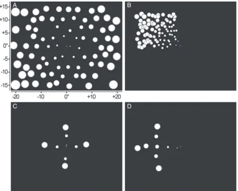
Phosphene layouts
There were four (4) different configurations of phosphenes in the experiment, supposedly evoked by four (4) different implants. Figure 1 shows the four phosphene layouts. The first one, 100Central, was used as a reference layout with 100 electrodes spread across a large portion of the visual field (Fig. 1A). A typical drop rate of 10% was applied to account for nonfunctional electrodes (12,18). Therefore, only 90 phosphenes were actually displayed. This optimal layout was compared with an array with the same number of electrodes but implanted at the periphery (100Lateral, Fig. 1B), as it would be for an implant partly covering the right side of the retina or a corti-cal implant over the most accessible part of the primary visual cortex. We also simulated a neural
interface with a limited number of electrodes (nine) implanted over the fovea (Fig. 1C: 9Central) or lat-erally (Fig. 1D: 9Lateral). For a situation where the system would interactively guide the user, the layout in the form of a cross shape is efficient to indicate the cardinal directions (left/right/up/down) as well as the distance (two phosphenes at different distance from the center). No dropout was simulated for these nine electrode layouts as individual testing of the elec-trodes could be pursued during the implantation pro-cedure to ensure that each electrode is functional.
The first block of the experiment used the 100Central layout. For the three following blocks, the different phosphene layouts were used according to a pseudo-random order that differed among subjects. This procedure removed a potential influence of training on behavioral performance. After these four blocks, the subjects were retested in a fifth block with the 100Central layout to observe the potential effect of learning. The subjects first followed a quick famil-iarization phase when starting with a new phosphene layout.
To simulate the experience with a real implant, which elicits phosphenes at a fixed position in the visual field, the instructions were to fixate a small purple cross at the center of the screen and to use head movements instead of eye movements to induce phosphene variations. The eyes were tracked within the head-mounted display (HMD), and the experi-menter monitored the subject’s eye position during each trial. The subjects were asked to look at the
cross as soon as their eyes moved away from the central fixation spot. Most of the subjects had no difficulty in fixating on the central cross. However, two to four subjects, for a few trials, moved the eyes away from the cross, especially for conditions with lateral displays. The experimenter had to remind them to keep fixating on the central cross. Their per-formance was not significantly different compared with the performance of the other subjects.
Material
The phosphene layouts were displayed with a 1280 × 1024 resolution in an NVisor SX-60 HMD (NVIS Inc., Reston, VA, USA), subtending 44 × 34° of visual angle. The binocular camera (Bumblebee II - 03S2, Point Grey, Richmond, BC, Canada), mounted at the top of the HMD, captured two video streams at a resolution of 320 × 240 pixels and a rate of 48 frames per seconds. The viewing angle was 100° and the acquired images were combined to recon-struct depth using Triclops API from Point Grey. Eye position was monitored with an eye-tracker (Eye-Track 6 - VR6; Applied Science Laboratories, Bedford, MA, USA) compatible with the NVisor HMD.
The experiment was controlled by a PC running home-made software developed in C++. A second computer was used to perform object recognition and distance estimation in real time. A third computer was used for eye-tracking as well as phosphene rendering.
FIG. 1. The four phosphene layouts used
in the experiment: (A) 100Central, (B) 100Lateral, (C) 9Central, and (D) 9Lateral. X and Y axis represent the field of view in degrees of visual angle. Subjects had to fixate constantly on the small cross at the center of the screen.
Computer vision
In this experiment, SpikeNet Vision (SNV) (bio-inspired algorithm from SpikeNet Technology, Toulouse, France) was used to perform real-time rec-ognition of learned objects. SNV is a supervised model-based object detection algorithm that relies on large-scale networks of asynchronously firing neurons (34). SNV is based on the principle that the earliest firing neurons generally correspond to the most strongly activated ones. Selecting these first firing neurons only is a way to respond to the most salient features in the image. As such, SNV is defined as a model-based object recognition engine relying on saliency maps. SNV is very rapid (it can simultane-ously detect a large number of targets within 20 ms) and is quite resistant to image transformations, which makes it a good choice for this type of application (31). The target objects were seven common objects (a computer mouse, a cordless telephone, a credit card, a cup, a small bottle, a remote control, and a jar of chocolate spread). They were all learned by SNV in several positions on the table. Each object required from 15 to 35 models (depending on viewing angle and distance) to be recognized everywhere on the table. When detection occurred, the position of the target was converted into the coordinate system of the phosphene array. Then, when an object was rec-ognized and localized within the image, its position was rendered to the subject by lighting up a unique phosphene at the closest location in the phosphene layout. Therefore, the subject did not receive any clue about the distance or the shape of the detected object.
Although accuracy of the algorithm was not evalu-ated specifically in the current study, we computed a rate of misses (number of times a target was visible in the field of view of the camera and not detected) during the experiments. The analysis of 24 random
trials (6 per condition) showed that there were less than 5% misses per trial in average. The detection rate was favored over the false alarm rate, so that the subject could be confident that a target present in the camera image would be detected with certainty and displayed as a phosphene. The false alarm rate was around 0–5 per trial, generally corresponding to distant objects in the room. An estimation of the distance to the detected objects was available through stereo correspondence performed by Triclops SDK from the camera provider. These dis-tance estimates were used to filter out targets detected farther than 80 cm away (distance of the farthest targets). This filtering decreased the number of phosphenes displayed on false detections. In real life, similar filtering could be used when the subject is looking for objects in his or her peripersonal space. It is important to note that the remaining false detec-tions, within the peripersonal space, were much less stable in time than correct detections. Then, the sub-jects quickly learned to ignore them when relying on phosphene stability.
SPV
In our device, the simulated implant is fully described in a text file, which contains the number and location of the simulated electrodes, the dropout percentage (defective electrodes are randomly selected), and the quantity of jitter added on the evoked phosphene position.
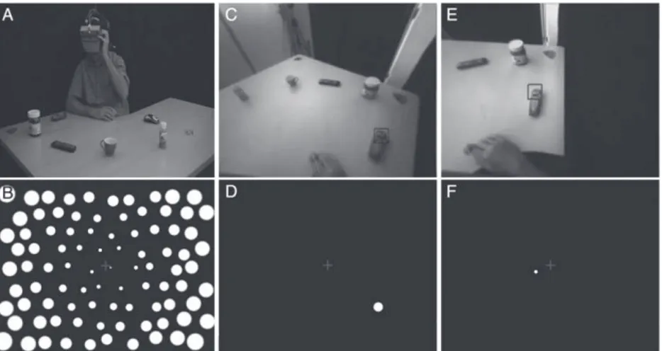
Figure 2C shows an example of a simulated implant, with 100 phosphenes spread over the visual field. The phosphenes were white with a luminance of 100% over a black background. They were roundly shaped with a Gaussian profile. The size of the phosphenes ranged from 0.4° to 3.4° depending on their distance from the center of the screen (fovea). This simulates the cortical magnification factor,
FIG. 2. (A) Global view of the setup with
seven objects disposed on the table in front of the subject. The subject is wearing an HMD, on top of which a binocular camera is mounted. (B) Current phosphene layout. Here, all the phosphenes of 100Central con-dition are lit up for illustration purpose. Only one phosphene is switched on at any moment during the experiment. (C) Subjec-tive view from the head camera with the detected target indicated with a square. (D) SPV rendering corresponding to panel C: the phosphene closest to the target object is switched on. (E and F) Same as panels C and D after the subject moved the camera to bring the detected object in the center of the visual field. A different phosphene is now switched on, to reflect the new position of the detected object in the visual field.
where microstimulation of the visual cortex evokes phosphenes with an increasing size as eccentricity increases. A random jitter was added to the location of the simulated phosphenes (maximum amplitude of half a degree of visual angle) to model the discrep-ancy observed between the expected and the real location of phosphenes elicited by cortical microstimulation (18). Finally, the SPV simulates nonfunctional or ineffective electrodes, which are usually reported to count up to 10% (4).
Procedure
Subjects were seated on a swivel chair in front of a table with a quadrant shape. They were wearing an HMD on top of which a stereo camera was attached. The subjects were also wearing earphones to listen to instructions during the experiment. Because the device was too heavy (around 1.5 kg) to be tolerated during 2 to 3 h, a lifting system was installed on the ceiling of the room, vertically to the chair, to subtract around 1 kg of the total mass. Great care was taken to lessen any discomfort experienced by the subjects wearing the device and regular breaks were made between the blocks of trials.
The task was to locate a precise object among seven objects positioned on a table. The subjects only relied on the phosphene-like information displayed in the SPV to locate the object. To evaluate the func-tional performance of the device in the task, the subject had to reach the object with the hand. Before the beginning of the experiment, the subjects were given approximately 5 min to get familiar with the setup and practiced for a few trials. The experiment was divided in five blocks, corresponding to the four phosphene layouts. The first block always included the 100Central condition and was repeated at the end (fifth block). A block was divided in six series of seven trials for a total of 42 trials per phosphene layout. So each subject performed 210 trials in total (42 trials per block × 5 blocks).
There were seven different objects to locate, pseudo-randomly located among 11 identified loca-tions on the table. The subjects did not see the table and the 11 positions before the experiment. During a post-experiment debrief, 10 out of the 12 naive sub-jects reported that they thought that obsub-jects were placed at completely random locations on the table. Furthermore, there was no significant difference between the first three and the last three trials in each series. These observations confirm that the subjects did not notice or take advantage of any organiza-tion in the spatial display of the objects or in the procedure.
A trial started with the announcement, in the ear-phones, of the object to locate. The models corre-sponding to this object were loaded into SNV and the one phosphene closest to the object’s location within the camera image was lit up. The subject could then freely move the head to find the location of the object and try to touch it with the right hand. After a contact with the table or the object, the subject had to bring back the hand to the resting position and wait for the announcement of the next object. A trial was correct if the first object to be touched was the target object, and if this contact occurred within 3 SDs of the average time to touch an object (calculated afterward on all subjects together). Accidental contact (with the wrist or elbow) with other objects placed in front of the target was not considered as an error, and the touched object was immediately relocated to another position. The remaining trials were considered as incorrect.
Once the subject had made an attempt for each of the seven objects, music was played through the ear-phones to mask any auditory clues produced by the experimenter moving the objects into a new configu-ration. After six series with a phosphene layout, a new phosphene layout was loaded for the next block of six series. The whole experiment had an average duration of two and a half hours, and was followed by a questionnaire about the experiment. The experi-ment was entirely filmed with the subject’s agree-ment for post hoc analysis. The layout of the objects on the table and the sequence of the objects to touch were randomly generated and were different for each subject. With seven objects randomly located, the probability of reaching the target object by chance is 1/7 (chance level = 14.3%).
After a few trials, the behavior of the subjects became stereotyped. They adopted an efficient strat-egy to determine rapidly and precisely the location of the objects. If the object was not detected in the first place (resting position, “looking” straight ahead), the subject started moving their head from one side to the other. Detection frequently occurred in periph-ery (Fig. 2C,D). As soon as it occurred, the subject turned their head toward the target to stabilize the phosphene in the center of the visual field (Fig. 2E,F). Obviously, with lateral arrays (9Lateral and 100Lateral), the most central position was a few degrees off-centered. Once the phosphene was stable, the user could reliably approximate the posi-tion of the object before reaching it.
Data analysis
Analysis of the behavioral results included the accuracy (the percentage of correct trials among all
trials) and speed (time between the announcement of the target object and the contact with the correct objet). This analysis was performed on the log files of the experiment with Matlab (Mathworks, Natick, MA, USA). Statistical tests were completed with R software (R Foundation, Boston, MA, USA).
Because time measurements tend to have long tail distributions, we used median times instead of averaged times. Indeed, medians are less sensitive to distribution skewness. We then performed non-parametric statistics. Comparisons between two groups or conditions were based on Wilcoxon tests. Comparisons with more than two conditions used Friedman’s test. The significance level for all tests was set to 0.05.
RESULTS
The grand average time to touch an object for the 14 subjects in all 5 conditions was 20.0 s. Trials that were longer than three times the average SD (3 × 17.4 = 72.2 s) were discarded. They represented only 1.4% of the trials. After video verification, nearly all of them corresponded to technical issues (e.g., eye-tracker repositioning) or unexpected pauses (problems with the HMD cables, HMD dis-comfort).
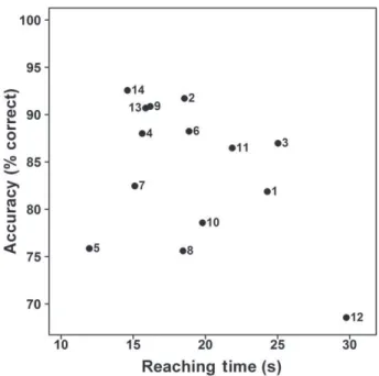
The results of subject (S) 12 strongly contrasted with those of the other subjects. His average reaching time was longer than 3 SDs above the average of all the other subjects (29.8 s vs. 18.2 s), and his accuracy was more than 3 SDs below the average accuracy of the other subjects (68.5% vs. 85.4%) (see Fig. 3). The subject was hence considered as an outlier and was excluded from further analysis. Without S12, the average time for correct reaching was 18.2 s (SD average: 3.8) and the accuracy was 85.4% correct (SD average: 5.9).
Learning effect
The same 100Central layout was used in the first (100Central1) and the last (100Central2) block for each subject to observe a potential learning effect between the first and last blocks of the experiment. Three blocks of 42 trials separated the first (100Central1) and last (100Central2) blocks. A Wilcoxon test on speed (z = 1.72, P = 0.048) and accuracy (z = −2.31, P < 0.018) revealed significant differences with subjects being faster and more accu-rate to perform the task at the end of the experiment. These effects were limited with half a second decrease in reaching time (16.0 vs. 16.6 s) and a 6% increase in accuracy (91.4% vs. 85.7%) after a 2-h experience with the device. In the next sections, 100Central2 is used as the reference layout.
We previously mentioned that two subjects had earlier experience with the device. These two non-naive subjects (S13 and S14, see Fig. 3) had perfor-mances that were comparable with those of some naive subjects, namely S2, S4, and S9. This result also indicates that learning was very limited.
Phosphene layout
The main independent variable of the experiment was the phosphene layout. Figure 4 represents the performance of the subjects across the different phosphene layouts. Figure 4A shows the median time to reach an object and Fig. 4B the percentage of correct reaching. Friedman’s tests indicated that the phosphene layouts had a significant effect on the average time to reach an object (χ2= 7.98, degree of
freedom [d.f.] = 3, P = 0.046) but not on the percent-age of correct reaching (χ2= 7.14, d.f. = 3, P = 0.067).
Post hoc analysis for the reaching time did not reveal any significant difference between specific conditions (significant global effect only).
Number of electrodes
One goal of the experiment was to assess the pos-sibility to perform object localization with a small set of electrodes. To answer this question, we compared conditions with 9 electrodes (9Central and 9Lateral) versus conditions with 100 electrodes (100Central2
FIG. 3. Average time to reach an object (in seconds) as a
func-tion of accuracy (% correct) for all subjects in all condifunc-tions together. In the lower right-hand corner, subject S12 clearly appears as an outlier. S13 and S14, the two non-naive subjects, have a performance comparable with S2, S4, and S6.
and 100Lateral). There was no significant difference, neither in the reaching time (z = −1.12, P = 0.26) (Fig. 4C) nor in the accuracy of the response (z = −0.47, P = 0.69) (Fig. 4D).
Position of electrodes
Another aim of the study was to determine the impact of the position of the phosphenes in the visual field on task performance. When comparing central (100Central2 and 9Central) with lateral (100Lateral and 9Lateral) layouts, there was a significant differ-ence in reaching time (Wilcoxon: z = 2.75, P < 0.001) and in accuracy (Wilcoxon: z = −4.17, P < 0.001). As expected, this indicates a better performance when phosphenes were closer to the line of sight than when they were presented in periphery.
Object-to-object performance
Seven different objects were used in this experi-ment and although the choice of these particular objects was arbitrary, some general observations can be derived from the analysis of the performance across the different objects. The analysis of variance for the median reaching time reveals a significant difference between objects (χ2= 34.32, d.f. = 6,
P <0.01). A significant difference was also present
for the percentage of successful reaching (χ2= 17.81,
d.f. = 6, P < 0.001). The Tukey test in post hoc analy-sis reveals that for the average time of reaching, the credit card differs from all other objects with a much longer time. Concerning the success rate, we observed a better performance for the spread jar than the other objects, and a worse performance for the credit card and the bottle than the other objects.
DISCUSSION
Number and localization of the electrodes
Many SPV studies relying on the scoreboard method showed that 300 to 500 phosphenes are needed to start reading a text (11,14) and that 1000 to 2000 phosphenes are required to identify faces (18) or recognize visual scenes (17). Few SPV studies con-sidered object recognition tasks, often with simplified situations. The phosphene count required to recog-nize objects was found between 250 and 500 in favor-able conditions (14,17) (a reduced set of large white objects on a dark background). With an embedded localization algorithm, the number of phosphenes needed to localize and reach an object in the peripersonal space with a high accuracy is drastically reduced. The results of the present experiment show
FIG. 4. (A) Median reaching time (in seconds) and (B) mean reaching accuracy across phosphene layouts. (C) Median reaching time and (D) mean reaching accu-racy for small and large arrays of electrodes (respectively 9 and 100 electrodes). The horizontal line indicates chance level in the task (=14.3 %).
that a 10 × 10 array of electrodes is sufficient to reach accuracy higher than 85% in a challenging object recognition task, without sacrificing speed. All seven objects were present at the same time and finding the target required head scanning movements most of the time. In these conditions, the average time to touch the correct object was 17 s and 20% of the trials lasted less than 10 s. A recognition and reaching task with an optical nerve implant was published by Duret et al. (35). The task was much simpler: locating and reaching a single white object on a black table, and an average duration of 40 s was necessary to perform it, although comparison is difficult as this result was obtained with a real neuroprosthesis. Another recently published study by Zrenner’s group (22) also reported object recognition and local-ization tasks, with a retinal implant. Four white objects among six were placed around a white plate on a black table in front of the subjects. One point was awarded for each correctly recognized object and the average score for the eight subjects was 1.5 out of 4, which is low but still significantly different from chance level. The time to recognize the objects was not reported but the subjects had no time constraints whatsoever.
In addition to the layouts with a hundred elec-trodes, we tested object recognition and reaching performance with nine phosphenes only, organized as a plus sign. Although the number of phosphenes was drastically reduced, we were expecting similar accuracy. Indeed, we made the hypothesis that the accuracy mainly depends on the robustness of the embedded vision system and not on the number of electrodes/phosphenes in the implant that then serves as a “guiding device.” This is what happened as the accuracy for the 2 array sizes (9 vs. 100 elec-trodes) was virtually the same with 85% correct. However, we were expecting a longer time to reach the objects, at least to compensate for the poor space mapping available with nine electrodes only. Surpris-ingly, the results were very close: the median reach-ing time was not significantly different with 17.0 s for 100 electrodes and 18.2 s for 9 electrodes (P = 0.26). Because this mode of operation is not relevant for perceiving a visual scene layout, it could be switched on and off, on user demand, within a more important array (i.e., current 60 electrodes arrays).
Several sites along the visual pathway are possible candidates to insert a neural implant such as the retina, the optic nerve, the thalamus, or the visual cortex. However, the surgery to insert a neural implant into the optic nerve or the thalamus is espe-cially difficult. In addition, their topical organization is quite complex, especially for the optic nerve, which
induces nonhomogenous distributions of the phosphenes (35). The more obvious locations for visual implants are the retina or the cortex and most of the development efforts are targeting these struc-tures. The placement of the array of electrodes within these structures is, however, also constrained: epiretinal implants are placed over the macula, a few degrees apart from the optical axis, to avoid the area where ganglion cell bodies are repelled on the rim of the fovea. Subretinal or suprachoroidal implants could be implanted directly behind the fovea if no residual vision subsists. In this study, we have focused on simulating cortical implants, but the 9Lateral array (Fig. 1D) would require minor adjustments to accurately simulate an epiretinal implant, the same being true for 9Central layout (Fig. 1C) with subretinal or suprachoroidal implants. If we consider a cortical implantation site, we should note that in area V1 of the visual cortex, the visual field corre-sponding to the fovea is represented within the calcarine sulcus and the peripheral part of the visual field extends externally to the sulcus, on the posterior pole of the occipital lobe, which is more easily acces-sible for an implantation. Accordingly, a cortical implant would preferably be placed in the periphery of the visual field (9Lateral, Fig. 1D or 100Lateral, Fig. 1B). We evaluated the usability of such arrays of electrodes/phosphenes positioned laterally com-pared with arrays positioned centrally and showed that the localization and reaching times were slightly increased (+2.7 s) and the accuracy was decreased by 7.1%. In this condition, the user must compensate for the absence of three quarters of the visual field, including its central portion. Then, we would have expected a larger impact on performance, in keeping with the large performance drop demonstrated by Sommerhalder et al. (36) in reading tasks at 10–20° of eccentricity. This difference of performance could be explained by the efficient use of the integrated infor-mation provided to the user in the form of unique phosphenes indicating without ambiguity the posi-tion of the target in space. A complementary expla-nation is that reading in the peripheral field requires high-resolution vision, which is not the case for guiding the hand toward a unique object in space.
With these different simulations, we showed that the phosphene number and location play a marginal role in the execution of a specific visuomotor task, that is, locating and reaching an object in the peripersonal space. With this recognition and local-ization method, the absence of 10% of the phosphenes (simulation of nonfunctional electrodes) or the jitter in the position of the phosphenes did not affect the performance.
Learning
Because the same array (100Central) was used at the beginning and the end of the experiment, it was possible to look for a potential learning effect. After 2 h using the device, the success rate increased sig-nificantly (+5.7%), while the time needed to localize an object slightly decreased (also significantly: −0.7 s). Still, this corresponded to a performance pro-gression by a few percentage points. It was reaching a plateau before the end of the first 100Central block and may be characterized as a familiarization effect. Although the interaction with the SPV was straight-forward, additional clues could be used after some practice to increase the performance. First, the sub-jects had to learn how to filtrate the possible false detections from the computer vision system by relying on stable phosphenes and ignoring flickering phosphenes. The subjects probably also learned to evaluate the angle on the pitch axis of the camera to accurately determine the distance of the objects on the table and avoid contact with the closest objects. Other visual tasks (reading, object recognition, eye-hand coordination, etc.) executed in SPV showed a learning effect (14), which was also the case for real implants based on the scoreboard approach (26). The improvement is generally attributed to perceptual learning, as well as the acquisition of the expertise required to extract meaningful information from a constantly changing set of illuminated phosphenes.
The very weak learning effect observed during the current experiment could be related to the simplicity of the information to process: only one phosphene, corresponding to one identified object. With this ren-dering method, the mapping between the rendered phosphenes and the position of objects in space is straightforward and does not require any expertise. The only thing to estimate is the distance, which can be deduced from head tilt after a few trials. The ability to fully use the implant right after surgery would give a major advantage to such a neuroprosthesis.
Computer vision in neuroprosthetics
There were important performance differences between the objects to locate. The chocolate spread jar, for example, led to the best behavioral perfor-mance and was considered as easy by all subjects. On the contrary, the credit card led to poor performance and was considered as the hardest object to locate by the subjects. These results first come from differences in detection performance of the artificial vision system. The computer vision algorithm relies on the salient features of an object. With this algorithm, an object with a complex shape or a rich texture is easier
to locate than a simple object. This is what happened with the credit card, being more prone to misses (absence of detection) or false alarms than other objects.
To reach a good detection performance during the whole experiment, 15–35 models were created for each object, which ensure that these objects could be recognized at any position in the peripersonal space. In less controlled situations, as in a house for example, the number of objects to recognize would be much larger and supervised learning of the objects would be impractical. Fortunately, several solutions exist. First, we recently observed the advent of large databases of tagged images (37) where objects are identified by their name and shape. The project Google Goggles also demonstrates that automatic tagging of a large variety of objects within natural images is already possible. The growing number of pictures available over the Internet constitutes an expanding database to train and improve such algo-rithms. Second, we may also envision a system with collaborative working or crowdsourcing to rapidly constitute a database of tagged images that could be specifically useful for blind people (38). Finally, object recognition algorithms that simultaneously model and track SMAT objects (they automatically generate new models of the objects to keep the track-ing effective) may also be considered to constitute efficient databases (39).
In the meantime, the efficacy of current algorithms could be improved by tagging the objects with stick-ers whenever possible at home or at work for example. This tagging would ease the detection and discrimination of objects by the artificial vision system. Another idea would be to focus on specific and important objects such as faces or blocks of text to constrain the visual detection difficulties and still convey pertinent information about the visual scene. In such a case, the SNV algorithm could be replaced easily with specialized algorithms dedicated to spe-cific needs (e.g., text or face detection algorithms [40,41]).
Usage scenario
In the present study, we evaluated the usability of a visual neuroprosthesis based on object recognition and localization. Although encouraging, the results are specific to a precise context: the user is looking for an explicit object in his or her surroundings. The restriction applied to a particular object (it could be a set of objects) is necessary because the bandwidth of the implant is limited, and the user only knows the 2D location of the target and nothing about its shape or distance. Displaying too many objects
at once would clutter the view and render the neuroprosthesis unusable. A real-life application of this system may rely on two different modes. First, according to the ongoing task or context, the system may activate a few preselected models only (faces, blocks of text, doors). Second, the user may interact with the neuroprosthetic device to select a precise object or a set of objects to look for. These different modes could be very easily and discretely selected on an adapted interface.
Efficient interaction could rely on vocal recogni-tion to input names of objects or people to find. Inter-faces implying gesture recognition, either from cameras (Kinect from Microsoft) or myo-electrical devices (Myo band from Thalmic Labs) are also becoming a reality and could be used to interact more naturally with the device. It is also quite easy to design automatic modes where human faces in the peripersonal space would be continuously located and displayed. According to the task that the user is doing, automatic mapping of space could provide the main landmarks of a specific place, including, for example, the doors, windows, tables, and chairs in a room, or the public transportation logos in the street. These different modes could be selected orally or manually depending on the interface.
CONCLUSION
A few decades after the cochlear implant, retinal implants are improving and are close to restoring an impoverished vision to blind people. Depending on the task to perform, 500 to 1000 electrodes are required to restore functional visual perception with a classical scoreboard method (6,42). In this study, we proposed an alternative method based on object rec-ognition in order to display pertinent information only. With this method and in the context of this experiment, only nine electrodes were necessary to restore basic visuomotor processes such as object localization and reaching.
Acknowledgments: We acknowledge Florian Dramas who provided valuable help for setting up the experiment. We also thank Simon J. Thorpe for numerous advices and support.
REFERENCES
1. Brindley GS, Lewin WS. The sensations produced by electri-cal stimulation of the visual cortex. J Physiol 1968;196:479–93. 2. Dobelle WH, Mladejovsky MG, Girvin JP. Artificial vision for the blind: electrical stimulation of visual cortex offers hope for a functional prosthesis. Science 1974;183:440–4.
3. Humayun MS, de Juan E, Dagnelie G, Greenberg RJ, Propst RH, Phillips DH. Visual perception elicited by electrical
stimulation of retina in blind humans. Arch Ophthalmol 1996;114:40–6.
4. Schmidt EM, Bak MJ, Hambrecht FT, Kufta CV, O’Rourke DK, Vallabhanath P. Feasibility of a visual prosthesis for the blind based on intracortical microstimulation of the visual cortex. Brain 1996;119:507–22.
5. Veraart C, Wanet-Defalque M-C, Gérard B, Vanlierde A, Delbeke J. Pattern recognition with the optic nerve visual prosthesis. Artif Organs 2003;27:996–1004.
6. Dobelle WH. Artificial vision for the blind by connecting a television camera to the visual cortex. ASAIO J 2000;46: 3–9.
7. Humayun MS, de Juan E, Weiland JD, et al. Pattern electrical stimulation of the human retina. Vision Res 1999;39:2569–76. 8. Humayun MS, Dorn JD, da Cruz L, et al. Interim results from the international trial of Second Sight’s visual prosthesis. Oph-thalmology2012;119:779–88.
9. Buffoni L-X, Coulombe J, Sawan M. Image processing strat-egies dedicated to visual cortical stimulators: a survey. Artif Organs2005;29:658–64.
10. Chuang AT, Margo CE, Greenberg PB. Retinal implants: a systematic review. Br J Ophthalmol 2014;98:852–6.
11. Cha K, Horch KW, Normann RA, Boman DK. Reading speed with a pixelized vision system. J Opt Soc Am A 1992;9:673–7. 12. Dagnelie G, Barnett DG, Humayun MS, Thompson RW. Paragraph text reading using a pixelized prosthetic vision simulator: parameter dependence and task learning in free-viewing conditions. Invest Ophthalmol Vis Sci 2006;47:1241– 50.
13. Cha K, Horch KW, Normann RA. Mobility performance with a pixelized vision system. Vision Res 1992;32:1367–72. 14. Hayes JS, Yin VT, Piyathaisere DV, Weiland JD, Humayun
MS, Dagnelie G. Visually guided performance of simple tasks using simulated prosthetic vision. Artif Organs 2003;27:1016– 28.
15. Fornos AP, Sommerhalder J, Pittard A, Safran AB, Pelizzone M, Pérez Fornos A. Simulation of artificial vision: IV. Visual information required to achieve simple pointing and manipu-lation tasks. Vision Res 2008;48:1705–18.
16. Li S, Hu J, Chai X, Peng Y. Image recognition with a limited number of pixels for visual prostheses design. Artif Organs 2011;36:266–74.
17. Zhao Y, Tian Y, Liu H, Ren Q, Chai X. Pixelized images recognition in simulated prosthetic vision. 7th Asian-Pacific Conference on Medical and Biological Engineering—IFMBE Proceedings. 2008;492–6.
18. Thompson RW, Barnett DG, Humayun MS, Dagnelie G. Facial recognition using simulated prosthetic pixelized vision. Invest Ophthalmol Vis Sci2003;44:5035–42.
19. Normann RA, Maynard EM, Rousche PJ, Warren DJ. A neural interface for a cortical vision prosthesis. Vision Res 1999;39:2577–87.
20. Zrenner E, Wilke R, Sachs H, et al. Patients allow recognition of letters and direction of thin stripes. World Congr Med Phys Biomed Eng - IFMBE Proc2009;25:444–7.
21. Chow AY, Chow VY, Packo KH, Pollack JS, Peyman GA, Schuchard R. The artificial silicon retina microchip for the treatment of vision loss from retinitis pigmentosa. Arch Ophthalmol2004;122:460–9.
22. Stingl K, Bartz-Schmidt KU, Besch D, et al. Artificial vision with wirelessly powered subretinal electronic implant alpha-IMS. Proc R Soc B Biol Sci 2013;280:20130077.
23. Humayun MS, Weiland JD, Fujii GY, et al. Visual perception in a blind subject with a chronic microelectronic retinal pros-thesis. Vision Res 2003;43:2573–81.
24. Pérez Fornos A, Sommerhalder J, da Cruz L, et al. Temporal properties of visual perception on electrical stimulation of the retina. Invest Ophthalmol Vis Sci 2012;53:2720–31.
25. Chen SC, Suaning GJ, Morley JW, Lovell NH. Simulating prosthetic vision: I. Visual models of phosphenes. Vision Res 2009;49:1493–506.
26. Brelén ME, Duret F, Gérard B, Delbeke J, Veraart C. Creat-ing a meanCreat-ingful visual perception in blind volunteers by optic nerve stimulation. J Neural Eng 2005;2:S22–8.
27. Barnes N, He X, McCarthy C, et al. The role of vision process-ing in prosthetic vision. Annual International Conference of the IEEE Engineering in Medicine and Biology Society, 2012;308–11.
28. Parikh N, Itti L, Humayun MS, Weiland J. Performance of visually guided tasks using simulated prosthetic vision and saliency-based cues. J Neural Eng 2013;10:026017.
29. Bay H, Tuytelaars T, Van Gool L. Surf: speeded up robust features. Comput Vision–ECCV 2006;3951:404–17.
30. Lowe D. Object recognition from local scale-invariant fea-tures. Proceedings of the Seventh IEEE International Confer-ence on Computer Vision. IEEE, 1999;2:1150–7.
31. Dramas F, Thorpe SJ, Jouffrais C. Artificial vision for the blind: a bio-inspired algorithm for objects and obstacles detec-tion. Int J Image Graph 2010;10:531–44.
32. Lieby P, Barnes N, McCarthy C, et al. Substituting depth for intensity and real-time phosphene rendering: Visual naviga-tion under low vision condinaviga-tions. Annual Internanaviga-tional Con-ference of the IEEE Engineering in Medicine and Biology Society, 2011;8017–20.
33. McCarthy C, Barnes N, Lieby P. Ground surface segmentation for navigation with a low resolution visual prosthesis. Annual International Conference of the IEEE Engineering in Medi-cine and Biology Society, 2011;4457–60.
34. Thorpe SJ, Guyonneau R, Guilbaud N, Allegraud J-M, VanRullen R. SpikeNet: real-time visual processing with one spike per neuron. Neurocomputing 2004;58–60:857–64.
35. Duret F, Brelén ME, Lambert V, Gérard B, Delbeke J, Veraart C. Object localization, discrimination, and grasping with the optic nerve visual prosthesis. Restor Neurol Neurosci 2006;24:31–40.
36. Sommerhalder J, Oueghlani E, Bagnoud M, Leonards U, Safran AB, Pelizzone M. Simulation of artificial vision: I. Eccentric reading of isolated words, and perceptual learning. Vision Res2003;43:269–83.
37. Dong W, Socher R, Li L-J, Li K, Fei-fei L. ImageNet: A large-scale hierarchical image database. IEEE Conference on Computer Vision and Pattern Recognition. IEEE, 2009;248– 55.
38. Bigham JP, Jayant C, Miller A, White B, Yeh T. VizWiz::LocateIt—enabling blind people to locate objects in their environment. Computer Vision and Pattern Recognition Workshops, 2010;65–72.
39. Dowson NDH, Bowden R. Simultaneous Modeling and Tracking (SMAT) of Feature Sets. 2005 IEEE Computer Society Conference on Computer Vision and Pattern Recog-nition (CVPR‘05). IEEE, 2005;99–105.
40. Zhao M, Li S, Kwok J. Text detection in images using sparse representation with discriminative dictionaries. Image Vis Comput2010;28:1590–9.
41. Geismann P, Schneider G. A two-staged approach to vision-based pedestrian recognition using Haar and HOG features. 2008 IEEE Intelligent Vehicles Symposium. Ieee, 2008;554–9. 42. Merabet LB, Rizzo JF, Amedi A, Somers DC, Pascual-Leone A. What blindness can tell us about seeing again: merging neuroplasticity and neuroprostheses. Nat Rev Neurosci 2005; 6:71–7.