HAL Id: pastel-00005644
https://pastel.archives-ouvertes.fr/pastel-00005644
Submitted on 20 Dec 2009HAL is a multi-disciplinary open access archive for the deposit and dissemination of sci-entific research documents, whether they are pub-lished or not. The documents may come from teaching and research institutions in France or abroad, or from public or private research centers.
L’archive ouverte pluridisciplinaire HAL, est destinée au dépôt et à la diffusion de documents scientifiques de niveau recherche, publiés ou non, émanant des établissements d’enseignement et de recherche français ou étrangers, des laboratoires publics ou privés.
Sur des systèmes MIMO avec retour limité: distorsion
bout-à-bout, retour analogique du canal, et multiplexage
par couche
Jinhui Chen
To cite this version:
Jinhui Chen. Sur des systèmes MIMO avec retour limité: distorsion bout-à-bout, retour analogique du canal, et multiplexage par couche. domain_other. Télécom ParisTech, 2009. Français. �pastel-00005644�
In Partial Fulfillment of the Requirements for the Degree of Doctor of Philosophy
from TELECOM ParisTech
Specialization: Communication and Electronics
Jinhui Chen
On MIMO Systems with Limited Feedback:
End-to-End Distortion, Analog Channel Feedback,
and Layered Multiplexing
Defense scheduled on the 9th of July 2009 before a committee composed of:
Reporters Prof. E. Telatar, EPFL Prof. M. Debbah, SUP´ELEC Examiners Prof. R. Knopp, EURECOM
Associate Prof. P. Ciblat, TELECOM ParisTech Dr. M. Guillaud, FTW
pr´esent´ee pour obtenir le grade de Docteur de TELECOM ParisTech Sp´ecialit´e: Communication et Electronique
Jinhui Chen
Sur des Syst`
emes MIMO avec Retour Limit´
e:
Distorsion Bout-`
a-Bout, Retour Analogique du
Canal , et Multiplexage par Couche
Th`ese pr´evue le 9 juillet 2009 devant le jury compos´e de : Rapporteurs Prof. E. Telatar, EPFL
Prof. M. Debbah, SUP´ELEC Examinateurs Prof. R. Knopp, EURECOM
Maˆıtre de Conference HDR P. Ciblat, TELECOM ParisTech Dr. M. Guillaud, FTW
Abstract
In this thesis, we investigate the following three fields on input multi-output (MIMO) systems with limited feedback.
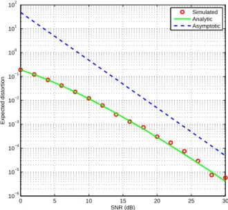
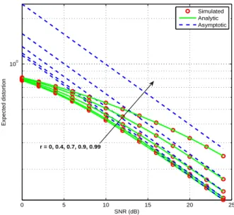
End-to-end distortion: The first part of the thesis presents the joint impact of antenna numbers, source-to-channel bandwidth ratio, spatial cor-relation and time diversity on the optimum expected end-to-end distortion in an outage-free MIMO system. In particular, based on the analytical ex-pression for any signal-to-noise ratio (SNR), the closed-form exex-pression of the asymptotic optimum expected end-to-end distortion at a high SNR is derived, comprised of the optimum distortion exponent and the optimum distortion factor. The simulation results illustrate that, at a practical high SNR, the analysis on the impacts of the optimum distortion exponent and the optimum distortion factor explains the behavior of the optimum ex-pected end-to-end distortion. The results in this part could be the perfor-mance objectives for analog-source transmission systems as well as a guid-ance on system design.
Analog channel feedback: In the second part of this thesis, we propose to apply orthogonal space-time block codes (OSTBC) with linear analog chan-nel feedback. Since MIMO chanchan-nel information is a sort of analog source vector, relative to quantized channel feedback, linear analog feedback has the advantages such as outage-free, self channel adaptation and low complexity. It is proved that the linear analog transmission method with OSTBC can achieve the matched filter bound (MFB) on received SNR. In comparison with the linear analog transmission method with circulant space-time block coding (CSTBC), the method with OSTBC performs better with respect to received SNR and mean-squared error. In comparison with the random vector quantization methods with different modulation schemes, the simu-lation results show that with respect to average direction error, the linear analog transmission method with OSTBC performs over any RVQ method
ii Abstract
with specific modulation scheme in the regimes of relatively high SNR and low SNR; with respect to average mean-squared error, it performs always better than the RVQ methods. We also evaluate the effect of applying the linear analog channel feedback with OSTBC to multiuser MIMO downlink beamforming. It is shown that the linear analog channel feedback with OS-TBC can make the system approach the optimum performance within a short latency.
Layered multiplexing: In the third part of this thesis, with respect to the systems with short blocks, a new layered multiplexing strategy is pro-posed to adapt an uncertain channel by Walsh layer-time coding, successive interference canceller and HARQ signaling. As illustrated by simulation re-sults, with respect to its high success rate, good performance on average latency and lower computational complexity, this strategy would be a good replacement to the widely-used adaptive QAM modulation strategy.
R´
esum´
e
Dans cette th`ese, nous ´etudions les trois sujets suivants sur les syst`emes de multiples entr´ees multiples sorties (MIMO) avec retour limit´e:
Distorsion bout-`a-bout: La premi`ere partie de la th`ese pr´esente l’impact conjoint des les nombres d’antenne, le ratio de bande passante de la source au canal, la corr´elation spatiale et diversit´e dans le temps sur l’esp´erance de la distorsion optimale bout-`a-bout dans les MIMO syst`emes sans panne. En particulier, repose sur l’expression analytique pour tout les ratios du signal au bruit (SNR), l’expression asymptotique de l’esp´erance de la dis-torsion optimal bout-`a-bout au SNR ´elev´e est d´eriv´e, compos´e de l’exposant de distorsion optimale et le facteur de distorsion optimale. Les r´esultats des simulations montrent que, `a un SNR ´elev´e pratique, l’analyse sur les impacts de l’exposant de distorsion optimale et le facteur de distorsion op-timale explique le comportement de la distorsion opop-timale bout-`a-bout. Les r´esultats pr´esent´es dans cette partie pourraient ˆetre les objectifs de perfor-mance pour les syst`emes qui transmettent les sources analogique et en outre les directives sur la conception du syst`eme.
Retour analogique du canal: Dans la seconde partie de cette th`ese, nous proposons d’appliquer le codage bloc d’espace-temps orthogonal (OSTBC) sur retour analogique lin´eaire du canal. Consid´erant l’information du canal MIMO est une sorte de source vectorielle analogique, par rapport au retour du canal quantifi´e, le retour analogique lin´eaire a les avantages comme sans panne, l’adaptation automatique au canal et peu complexe. Il est prouv´e que la m´ethode de transmission analogique lin´eaire OSTBC peut atteindre la borne de filtre adapt´e (MFB) sur SNR re¸cu. Par rapport en m´ethode analogique lin´eaire du codage bloc d’espace-temps circulant, la m´ethode lin´eaire analogique OSTBC obtient de meilleurs r´esultats `a l’´egard de SNR re¸cu et erreur quadratique moyenne (MSE) ; Par rapport en m´ethode de la quantification vectorielle al´eatoire, les r´esultats des simulations montrent
iv Abstract
que sous une contrainte stricte de latence, leur performances sont proches `a l’´egard de l’erreur moyenne au sens et la m´ethode lin´eaire analogique OSTBC ex´ecute encore mieux `a l’´egard erreur quadratique moyenne. Nous ´etudions ´egalement l’incidence de appliquer le retour lin´eaire analogique OSTBC au beamforming en liaison descendante pour multiutilisateurs MIMO et nous montrons que le retour lin´eaire analogique OSTBC peut rendre l’approche du syst`eme des performances optimales dans un temps de latence court.
Multiplexage par couche: Dans la troisime partie de cette th`ese, en con-sid´erant les syst`emes avec des blocs courts, une nouvelle strat´egie de multi-plexage par couches est propos´ee d’adapter un canal incertain par le codage couche-temps Walsh, l’annuleur d’interf´erence successif et HARQ signali-sation. Comme l’illustrent les r´esultats de la simulation, en raison de ses performances proches mais beaucoup moins complexe, cette strat´egie serait un bon substitut `a la strat´egie de modulation QAM adaptive qui est large-ment utilis´ee.
Acknowledgements
I would like first to extend my sincere thanks to my advisor Prof. Dirk T. M. Slock for letting me dictate the pace of my research, giving me freedom of a large extent on the choice of topics, his inspiring ideas, invaluable guidance and kind helps on all details, and for giving me invaluable insight into my research.
I would also like to extend my thanks to Dr. Uri Erez in Tel Aviv Uni-versity for the inspiring discussions between us, and Prof. Giussepe Caire in University of Southern California for kindly sending his breakthrough manuscript not-yet-published at that time.
I am grateful to my committee members, Prof. Emre Teletar, Prof. M´erouane Debbah, Prof. Raymond Knopp, Prof. Philippe Ciblat and Dr. Maxime Guillaud for their valuable inputs.
I would like to thank my friends at EURECOM and in Sophia. The list is too long to be put here. We had so much fun together and enjoyed our lives. Special thanks to Junbo and Randa for technical discussions and suggestions.
My sincere thanks to the secretaries at EURECOM for helping me deal-ing with all administrative thdeal-ings and the IT supporters for dealdeal-ing with computers and networks. All of them are nice.
Finally, I would like to thank my family and family-in-law who have always encouraged me in my quest for higher education and especially my husband and best friend of many years Wu Jiaqi for encouraging me and listening to my occasional laments and for supporting my many decisions.
Contents
Abstract . . . i Acknowledgements . . . v Contents . . . vii List of Figures . . . xi Acronyms . . . xiii Notations . . . xv 1 Introduction 1 1.1 MIMO systems with feedback . . . 11.2 End-to-end distortion . . . 2
1.3 MIMO channel estimate feedback . . . 8
1.4 Multi-layer transmission . . . 11
1.5 Thesis outline and contributions . . . 14
2 End-to-End Distortion: Uncorrelated MIMO Channel 17 2.1 Introduction . . . 17
2.2 System model . . . 18
2.3 Mathematical preliminaries . . . 19
2.4 Main results . . . 21
2.4.1 Optimum expected distortion at any SNR . . . 21
2.4.2 Asymptotic optimum expected distortion . . . 23
2.5 Numerical analysis and discussion . . . 27
2.6 Conclusion . . . 32
2.A Proof of Lemma 1 . . . 33
2.B Proof of Lemma 2 . . . 34
2.C Proof of Lemma 3 . . . 35
2.D Proof of Lemma 4 . . . 36
2.E Proof of Lemma 5 . . . 38 vii
viii Contents
3 End-to-End Distortion: Correlated MIMO Channel 41
3.1 Introduction . . . 41
3.2 Mathematical preliminaries . . . 42
3.3 Main results . . . 44
3.3.1 Optimum expected distortion at any SNR . . . 44
3.3.2 Asymptotic optimum expected distortion . . . 45
3.4 Numerical analysis and discussion . . . 54
3.5 Conclusion . . . 55
4 End-to-End Distortion: With Time Interleaving 59 4.1 Introduction . . . 59
4.2 System Model . . . 62
4.3 Main Results . . . 62
4.3.1 Optimum expected distortion at any SNR . . . 62
4.3.2 Asymptotic optimum expected distortion . . . 63
4.4 Interleaving Impact Analysis . . . 63
4.5 Conclusion . . . 67
5 Analog Channel Feedback 69 5.1 Introduction . . . 69
5.2 Space-time coding in analog transmission . . . 71
5.2.1 Channel model . . . 71
5.2.2 MFB on receive SNR . . . 71
5.2.3 OSTBC achieves SNRMFB . . . 72
5.2.4 OSTBC analog vs. RVQ digital . . . 75
5.3 CSIT acquisition by analog channel feedback . . . 81
5.3.1 Scheme description and channel model . . . 81
5.3.2 Mean squared error evaluation . . . 83
5.4 Multiuser MIMO downlink beamforming with analog channel feedback . . . 90
5.4.1 Scheme description . . . 90
5.4.2 Signal-to-interference ratio evaluation . . . 91
5.5 Conclusion . . . 93
6 Layered Multiplexing 95 6.1 Introduction . . . 95
6.2 General description and channel model . . . 96
6.3 Process description . . . 98
6.3.1 Walsh layer-time coding . . . 98
6.3.3 In the mth transmission when 2 ≤ m ≤ L
w . . . 100
6.3.4 When Lw< m ≤ M . . . . 101
6.4 An example with simulation results . . . 102
6.5 Conclusion and future works . . . 105
6.A Solving the equation array (6.16) . . . 106
List of Figures
1.1 Basic elements of a digital communication system . . . 3
1.2 Distortion exponents for Nt= Nr= 2 case . . . 5
1.3 Distortion exponents for Nt= 2, Nr= 4 case . . . 5
1.4 Impact of distortion factor . . . 7
1.5 The feedback model for our end-to-end distortion analysis . . 8
1.6 The feedback model for channel matrix or channel direction acquisition . . . 9
1.7 Broadcast strategy for single user, i.e, multi-layer transmis-sion for channel adaption without any feedback . . . 13
1.8 Rateless coding, i.e, multi-layer reliable transmission with ARQ signaling . . . 13
2.1 Uncorrelated channel, one of (Nt, Nr) is fixed to 5, η = 4, high SCBR. . . 29
2.2 Uncorrelated channel, Nt= 1, Nr= 2, η = 1.1, high SCBR . 30 2.3 Uncorrelated channel, Nt = 2, Nr = 2, η = 1.7, moderate SCBR . . . 30
2.4 Uncorrelated channel, Nt= 2, Nr= 2, η = 1, moderate SCBR 31 2.5 Uncorrelated channel, Nt= 1, Nr= 2, η = 0.99, low SCBR . 31 3.1 Uncorrelated and correlated channels, Nt = 4, Nr = 2, η = 10, high SCBR . . . 55
3.2 Uncorrelated and correlated channels, Nt = 2, Nr = 2, η = 1.7, moderate SCBR . . . . 56
3.3 Uncorrelated and correlated channels, Nt= 2, Nr = 2, η = 2, moderate SCBR . . . 56
3.4 Uncorrelated and correlated channels, Nt = 2, Nr = 2, η = 0.6657, low SCBR . . . . 57
xii List of Figures
4.1 Block diagram of the transmission model with perfect
inter-leaving . . . 61
4.2 With time interleaving, Nt= 2, Nr = 1, η = 0.25, low SCBR 64 4.3 With time interleaving, Nt= 4, Nr = 2, η = 1, high SCBR . 65 4.4 SCBR state transition with time diversity branches. Nt= 2, Nr= 3, η = 0.32, and ρ = 20dB. . . . 66
5.1 Wrong decision ratios of QPSK, 16QAM and 64QAM modu-lation schemes . . . 77
5.2 Average direction error comparison: OSTBC vs. RVQ . . . . 78
5.3 Average MSE comparison: OSTBC vs. RRVQ . . . 80
5.4 Linear analog channel feedback scheme . . . 81
5.5 MSE comparison: OSTBC vs. CSTBC . . . 88
5.6 Average MSE comparison: OSTBC vs. CSTBC . . . 89
5.7 Multiuser MIMO downlink channel with channel feedback . . 90
5.8 Average SIR comparison: OSTBC analog channel feedback with different latencies and upper bound . . . 92
6.1 A multi-layer system with HARQ . . . 96
Acronyms
Here are the main acronyms used in this document. The meaning of an acronym is usually indicated once, when it first occurs in the text. The English acronyms are also used for the French summary.
AWGN Additive White Gaussian Noise ARQ Automatic Repeat Request
CSTBC Ciculant Space-Time Block coding/code CQI Channel Quality Indicator (CQI)
CSI Channel State Information
CSIR Channel State Information at Receiver CSIT Channel State Information at Transmitter DMT Diversity-gain-to-Multiplexing-gain Tradeoff FDD Frequency Division Duplex
HARQ Hybrid Automatic Repeat Request HDA Hybrid Digital Analog
MAF Matched Filter Bound ML Maximum Likelihood MRC Maximum Ratio Combining MSE Mean Square Error
MIMO Multi-Input Multi-Output MISO Multi-Input Single-Output
OVSF Orthogonal Variable Spreading Factor QAM Quadrature Amplitude Modulation
OFDM Orthogonal Frequency Division Multiplexing QPSK Quadrature Phase-Shift Keying
OSTBC Orthogonal Space-Time Block Coding/Code RHS Right Hand Side
RRVQ Real Random Vector Quantization RVQ Random Vector Quantization
xiv Acronyms
SCBR Source-to-Channel Bandwidth Ratio SIC Successive Interference Cancelation SIMO Single-Input Multi-Output
SINR Signal-to-Interference-Noise Ratio SISO Single-Input Single-Output SSB Single-Side Band
STBC Space-Time Block Coding/Code STC Space-Time Coding/Code TDD Time Division Duplex
THP Thomlinson-Harashimma Precoding ZFBF ZeroForcing BeamForming
Notations
Ex Expectation operator over the r.v. x
|H| Determinant of the matrix H |x| Absolute value of x
bxc Floor operation, rounds the elements of x to the nearest integers towards minus infinity
dxe Ceil operation, rounds the elements of x to the nearest integers towards infinity
H∗ Conjugate operation
H† Conjugate transpose operation
HT Transpose operation
R Set of real numbers
R+ Set of positive real numbers Z Set of integer numbers
Z+ Set of positive integer numbers
H matrix
h vector
h scalar
CN Complex Normal Distribution B Beta distribution
U Uniform distribution
η Source-to-channel bandwidth ratio Ws Source bandwidth(Hz)
Wc Channel bandwidth(Hz)
Na Number of antennas at the end A
Nb Number of antennas at the end B
Nt Number of transmit antennas
Nr Number of receive antennas
Nmin Nmin = min Nt, Nr
xvi Notations
Nmax Nmax= max Nt, Nr
Lb Length of the block
Ls Length of the source vector
Ψ(a, c; x) Confluent hypergeometric function Γ(x) Gamma function B(m, n) Beta function ρ Signal-to-noise ratio R Rate Rs Source rate Rc Channel rate Po Outage probability D Distortion ED Expected distortion
ED∗ Optimum expected distortion ED∗
asy Asymptotic optimum expected distortion
∆ Distortion exponent
∆∗ Distortion exponent in ED∗ asy
µ∗ Distortion factor in ED∗ asy
βbf Feedback delay factor
Dans un syst`eme de communication sans fil, la condition de propagation d´etermine les performances du syst`eme aux restrictions comme la contrainte du pouvoir `a long terme ou `a court terme, le ratio de pouvoir du pic `a la moyenne, et une latence maximale. Bien que le mod`ele de canal et des infor-mations statistiques de propagation dans certains environnements peuvent ˆetre pr´edit [1–6], la r´ealisation de canal instantan´e est incertaine. Pour un canal en lente disparition, la connaissance de canal instantan´e `a l’´emmeteur pourrait aider un syst`eme am´eliorer ses performances [7–10].
Dans la pratique, non seulement les syst`emes duplex division frquence (FDD) utilisent les liaisons retours, mais aussi les syst`emes duplex `a division de temps (TDD) pour l’´etalonnage. Conform´ement `a la technique adapt´ee au canal et employ´ee par le syst`eme, l’information sur la liaison all´ee `a retour n’est pas n´ecessairement les informations compl`etes d’´etat du canal. Ce pourrait ˆetre une repr´esentation de la condition de la liaison all´ee qui est nomm´e comme retour limit´e.
Dans cette th`ese, nous ´etudions les trois sujets suivants sur les syst`emes de multiples entr´ees multiples sorties (MIMO) avec retour limit´e:
Distorsion bout-`a-bout: La premi`ere partie de la th`ese pr´esente l’impact conjoint des les nombres d’antenne, le ratio de bande passante de la source au canal, la corr´elation spatiale et diversit´e dans le temps sur l’esp´erance de la distorsion optimale bout-`a-bout dans les MIMO syst`emes sans panne. En particulier, repose sur l’expression analytique pour tout les ratios du signal au bruit (SNR), l’expression asymptotique de l’esp´erance de la dis-torsion optimal bout-`a-bout au SNR ´elev´e est d´eriv´e, compos´e de l’exposant de distorsion optimale et le facteur de distorsion optimale. Les r´esultats des simulations montrent que, `a un SNR ´elev´e pratique, l’analyse sur les impacts de l’exposant de distorsion optimale et le facteur de distorsion op-timale explique le comportement de la distorsion opop-timale bout-`a-bout. Les r´esultats pr´esent´es dans cette partie pourraient ˆetre les objectifs de perfor-mance pour les syst`emes qui transmettent les sources analogique et en outre les directives sur la conception du syst`eme.
Retour analogique du canal: Dans la seconde partie de cette th`ese, nous proposons d’appliquer le codage bloc d’espace-temps orthogonal (OSTBC) sur retour analogique lin´eaire du canal. Consid´erant l’information du canal MIMO est une sorte de source vectorielle analogique, par rapport au retour du canal quantifi´e, le retour analogique lin´eaire a les avantages comme sans panne, l’adaptation automatique au canal et peu complexe. Il est prouv´e que la m´ethode de transmission analogique lin´eaire OSTBC peut atteindre
La source d’entr´ee-sortie mai soit une s´equence analogique (d’amplitude continue) ou d’une s´equence num´erique (d’amplitude discr`ete). Quelle que soit la source, il y a toujours un compromis entre l’efficacit´e et la fiabilit´e. Pour transmettre une s´equence num´erique, le compromis se situerait entre l’efficacit´e spectrale (bits/s/Hz) et la probabilit´e d’erreur. Pour transmet-tre une s´equence analogique, sous l’hypoth`ese de source Gaussian blanc de bande limit´ee, le compromis serait entre le ratio de bande passante de la source au canal Ws/Wc(S5..97Tf15.75-1.64D[(c)]TJ/i fiabilit´e.
transmise sur un canal MIMO et le transmetteur connaˆıt la capacit´e de canal instantan´ee, nous analysons l’impact conjoint de le ratio de bande passante de la source au canal (SCBR), la diversit´e spatiale, la corr´elation spatiale et la diversit´ede temps `a l’esp´erance de la distorsion optimal bout-`a-bout. Les th´eor`emes suivants sont issus:
Th´eor`eme 1 (L’Esp´erance de la Distorsion Optimale sur Canal Non Corr´el´es).
Supposons une source gaussien blanche continue au temps de la bande pas-sante Ws et de la puissance Ps d’ˆetre transmise sur un canal MIMO non
corr´el´e de la bande passante Wc en disparition bloc. L’esp´erance de la dis-torsion optimal bout-`a-bout est:
EDunc∗ (η) = QNmin Ps|U(η)|
k=1 Γ(Nmax− k + 1)Γ(Nmin− k + 1)
pour tout ρ (4) `ou η = Ws/Wc (SCBR), Nmin = min{Nt, Nr}, Nmax = max{Nt, Nr}, et
U(η) est une Nmin× Nmin matrice de Hankel uij(η) = µ ρ Nt ¶−dij Γ(dij)Ψ µ dij, dij+ 1 −η2;Nρt ¶ (5) `ou dij = i + j + |Nt− Nr| − 1, 1 ≤ i, j ≤ Nmin, et Ψ(a, b; x) est la fonction
de Ψ (voir [16, pp. 257-261]).
Th´eor`eme 2 (L’Exposant de Distorsion Optimale sur Canal Non Corr´el´es).
L’exposant de distorsion optimale sur canal non corr´el´e ∆∗unc(η) = NXmin k=1 min ½ 2 η, 2k − 1 + |Nt− Nr| ¾ . (6)
Th´eor`eme 3 (Le Facteur de Distorsion Optimale sur Canal Non Corr´el´es).
Dfinir deux fonctions de quatre tuple κl(β, t, m, n) et κh(β, t, m, n) comme dans (7) et (8) sur le haut de cette page, pour β ∈ R+ et t ∈ {0, Z+}.
Le facteur de distorsion optimale µ∗
unc(η) est donn´ee comme suit:
1. Pour 2/η ∈ (0, |Nt−Nr|+1), d´enomm´e le r´egime SCBR haut (HSCBR),le
facteur de distorsion optimale est µ∗unc(η) = PsNt∆∗unc κh(
2
η, Nmin, Nmin, Nmax)
QNmin
k=1 Γ(Nmax− k + 1)Γ(Nmin− k + 1)
. (9) Il diminue de fa¸con monotone avec N( max).
κl(β, t, m, n) = Γ(n − m + 1)Γ(β−n+m−1)Γ(β) Qtk=2Γ(k)Γ(n − m + k) ×Γ(β−n+m−2k+2)Γ(β−n+m−2k+1)Γ(β−k+1)Γ(β−n+m−k+1) , t > 1; Γ(n − m + 1)Γ(β−n+m−1)Γ(β) , t = 1; 1, t = 0. (7) κh(β, t, m, n) = (Qt k=1Γ(k)Γ(n − m − β + k), t > 0; 1, t = 0. (8)
2. Pour 2/η ∈ (Nt + Nr − 1, +∞), d´enomm´e le r´egime SCBR faible (LSCBR),le facteur de distorsion optimale est
µ∗unc(η) = PsNt∆∗unc κl( 2
η, Nmin, Nmin, Nmax)
QNmin
k=1 Γ(Nmax− k + 1)Γ(Nmin− k + 1)
. (10) 3. Pour 2/η ∈ [|Nt− Nr| + 1, Nt+ Nr− 1], d´enomm´e le r´egime SCBR
mod´er´ee (LSCBR),le facteur de distorsion optimale est
µ∗unc(η) = PsNt∆ ∗ unc κl( 2 η,l,Nmin,Nmax)κh( 2
η−2l,Nmin−l,Nmin,Nmax)
QNmin k=1 Γ(Nmax−k+1)Γ(Nmin−k+1) , mod {2η + 1 − |Nt− Nr|, 2} 6= 0; PsNt∆ ∗ unclog ρ κl( 2
η,l−1,Nmin,Nmax)κh(η2−2l,Nmin−l,Nmin,Nmax) QNmin k=1 Γ(Nmax−k+1)Γ(Nmin−k+1) , mod {2 η + 1 − |Nt− Nr|, 2} = 0 (11) `ou l = ¹2 η+1−|Nt−Nr| 2 º .
Th´eor`eme 4 (L’Esp´erance de la Distorsion Optimale sur Canal Corr´el´es).
L’esp´erance de la distorsion optimale sur un canal MIMO spatialement corr´el´es est ED∗cor(η) = Q Ps|G(η)| Nmin k=1 σ |Nt−Nr|+1 k Γ(Nmax− k + 1) Q 1≤m<n≤Nmin(σn− σm) . (12) V
gij(η) = µ ρ Nt ¶−dj Γ(dj)Ψ µ dj, dj+ 1 −η2;σNt iρ ¶ . (13)
dj = |Nt− Nr| + j. σ = {σ1, σ2, · · · , σNmin} avec 0 < σ1 < σ2< · · · < σNmin
d´esignant les valeurs propres ordon´ees de la matrice de corr´elation Σ.
Th´eor`eme 5 (L’Exposant de Distorsion Optimale sur un Canal Corr´el´es).
L’exposant distortion optimale ∆∗
cor dans le cas de canal MIMO spatialment
corr´e´es est le mˆeme que l’exposant ∆∗
unc dans le cas de canal MIMO non
corr´e´es, i.e., ∆∗cor(η) = NXmin k=1 min ½ 2 η, 2k − 1 + |Nt− Nr| ¾ (14)
Th´eor`eme 6 (Le Facteur de Distortion Optimal surun Canal Corr´el´es). Le facteur de distortion optimale µ∗
cor(η) est donn´ee comme suit.
1. Pour 2/η ∈ (0, |Nt− Nr| + 1) (HSCBR), le facteur de distorsion
opti-male est µ∗cor(η) = NYmin k=1 σ− 2 η k µ∗unc(η). (15)
2. Pour 2/η ∈ (Nt+ Nr − 1, +∞) (LSCBR), le facteur de distorsion
optimale est µ∗cor(η) = NYmin k=1 σ−Nmax k µ∗unc(η). (16) 3. Pour 2/η ∈ [|Nt − Nr| + 1, Nt + Nr − 1] (MSCBR), le facteur de distorsion optimale est
µ∗cor(η) = (−1) l(l−1) 2 |V3(σ)| QNmin k=1 σ |Nt−Nr|+1 k Q 1≤m<n≤Nmin(σn− σm) × NminY−l k=1 (k)l (|Nt− Nr| − 2η + l + k)l µ∗unc(η) (17) VI
´ou l = bη2+1−|Nr−Nt|
2 c et chaque entr´ee de V3(σ) est
v3,ij = σ
− min{j−1,2η−dj}
i . (18)
Th´eor`eme 7 (Convergence).
lim
Σ→Iµ
∗
cor(η) = µ∗unc(η). (19) Th´eor`eme 8 (L’Esp´erance de Distorsion Optimale avec Entrelacement en Temps). L’esp´erance de distorsion optimale bout-`a-bout dans les syst`emes sur canal non corr´el´es en disparition de bloc avec parfait entrelacement en temps est
ED∗int(η) = Ps1−L [ED∗unc(Lη)]L. (20)
Au SNR ´elev´e, le ED∗
int asymptotique est de la forme
EDasy,int∗ = µ∗int(η)ρ−∆∗int(η). (21)
Donn´ee (20), on a
EDasy,int∗ (η) = Ps1−LED∗asy,uncL(Lη). (22)
Par cons´equent, l’exposant de distortion optimale est
∆∗int(η) = L∆∗unc(Lη), (23) comme dans [17] et le facteur de distorsion optimale est
µ∗int(η) = Ps1−Lµ∗uncL(Lη) (24)
3
Retour Analogique du Canal
Nous supposons que la transmission analogique lin´enaire sur un canal MIMO peuvent ´egalement b´en´eficier de la diversit´e spatiale `a venir ainsi que des degr`es de libert´e spatiale et il pourrait ˆetre obtenu par la codage bloc
Puisque, dans un syst´eme analogique lin´enaire, pour une source de unit´e norme, erreur quadratique moyenne (MSE) est l’inverse du SNR re¸cu et c’est la primaire m´etriques pour la transmission de la source analogique, nous pensons que, pour les syst`emes MIMO, la borne de filtre adapt´e (MFB) au SNR re¸cu (SNRMFB) est un objectif de performance plausible.
On voit que pour une m´ethode de transmission lin´eaire analogique, en raison de sa lin´earit´e, dans l’expression de l’esp´erance MSE (i.e., distorsion), la diverit´e spatiale ne d´emontre pas en l’exposant de distorsion sur le SNR transmettre mais dans le facteur de distorsion de cˆot´e, et le valeur absolue de l’exposant est toujours un. Il est connu que une m´ethode de transmis-sion non lin´enaire peut atteindre une value absolue sup´erieure l’exposant de distortion [18–22]. Toutefois, en prenant le facteur de distorsion en compte, une sch`eme non lin´enaire peut donner de meilleurs r´esultats pour le SNR ´lev’e impratique mais peut-ˆetre ne pas pour tout SNR.
En outre, en vertu d’une contrainte stricte de latence, une m´ethode de transmission lin´aire analogique serait plus efficace que une m´ethode de trans-mission avec quantification, mˆeme sur l’exposant de distorsion.
Dans la transmission analogique lin´enaire, `a supposer que la pleine puis-sance de transmission est utilis`epour transmettre, le vecteur d’une source analogique doit ˆetre r´eduite et r´epondre aux contraints du pouvoir trans-mettre. Dans ce fait, pour r´ecup´erer le vecteur de la source au r´ecepteur, un facteur d’´echelle doit ˆetre transmise sous une autre mani`ere. `A savoir, dans ce cas, seule la direction du vecteur de la source peut ˆetre transmise par la m´ethode analogique lin´enaire. Dans cette th`ese, pour simplifier, pour mesuer la MSE, nous supposons que le facteur d’´echelle est transmise par une autre mani`ere et connu `a le r´ecepteur parfaitment.
Alternativement, dans certains sc´narios, le r´ecepteur ne doit connaˆıtre les directions des vecteurs de la source, par example, en liaison descendte z´ero for¸cant beamforming (ZFBF) techniques, apr`es s´election de l’utilisateur, seules les directions de canal doivent ˆetre connus `a la station de base. Dans ces cas, l’´emetteur n’a pas besoin de connaˆıtre le facteur d’´echelle, la trans-mission purement analogique lin´enaire est suffisant. La m´etrique dans ces cas serait d’erreur de direction.
Si nous supposons que la information de la direction du canal doit ˆetre utilis´ee dans ZFBF, nous pourrions mesurer la performance d’un sch`eme de retour par la ratio du signal `a l’interf´erence (SIR) en liaison descendante, ce qui indique la d´egradation de l’approche ZFBF due aux bruits dans les proc´edures de formation et retour. Le borne sup´erieur sur le SIR serait le SIR dans l’hypoth`ese o`u il n’y a que du bruit dans la proc´edure de formation
leur fonctionnalit´e dans le processus de production. De cette formule 33), Wa(2) = · 1 1 1 −1 ¸ , Wa(2k) = · Wa(2k−1) Wa(2k−1) Wa(2k−1) −W a(2k−1) ¸ . (33)
on peut voir que, si nous utilisons une matrice Walsh ´echelle colonne-sage en tant que une matrice couche-temps dont les colonnes sont consid´er´es comme des couches et les lignes sont consid´er´es comme du temps, les interf´erences inter couche peut ˆetre supprim´e ou att´enu´e par l’ajout de lignes en place.
Dans la premi`ere transmission, la cible de l’allocation de puissance de couche est de s’assurer que pas de retransmission est requis lorsque tous les emph (SNRs de canal instantan´ee ) dans le bloc, ρh,1t = min{|h|2/|n
1t|2},
1 ≤ t ≤ T , sont sup´erieurs `a un certain seuil ¯ρ.
Pour savoir le sch`ema d’allocation de puissance, on doit r´esoudre un tableau ´equation des L + 1 ’equations
¯ ρh,1tPl l(¯ρh,1t Pl−1 l0=1Pl0+1) = ¯ρ, l = 1, . . . , L, PL l=1Pl = PL. (34)
En r´esolvant (34), on obtient le seuil de ρh,1t
¯ ρh,1t= L PL l=1l ¯ρ Ql−1 l0=1(l 0 ¯ ρ + 1) P (35)
et le sch`ema d’allocation de puissance
P1= ρ¯ρ¯ h,1t, Pl= l ¯ρ Ql−1 l0=1(l 0 ¯ ρ + 1) ¯ ρh,1t , 2 ≤ l ≤ L . (36)
Par cons´equent, le vecteur de multiplexage `a couche vec(w)1 est
w1 = ¡ √ P1 . . . √ PL ¢ . (37)
Au r´ecepteur, le vecteur re¸cu y1est trait´e par SIC de la couche sup´erieure sL`a la couche inf´erieure s1. Apr`es une couche est correctement d´ecod´e, SIC
recommence `a partir du haut vers le bas jusqu’ ce qu’il ne couche plus peut
ˆetre v´erifi´ee par le code de d´etection d’erreur ins´er´e dans le codage canal, par exemple code de redondance cyclique [1, 31–33]. Quand aucune couche de plus peut ˆetre dcod avec succ`es, le r´ecepteur retour un signal HARQ q1 du premier transmission bloc d’indiquer quelles couches n’ont pas encore ´et´e correctement d´ecod´es et l’´emetteur est tenu de pr´eparer la retransmission en cons´equence.
Dans notre syst`eme, les informations de la transmission en cours pour stocker dans C1 est une matrice Ym0 de taille L × T . Chaque ligen de Y0m est une variation du vecteur re¸cu apr`es annuler tous les interf´erences inter-couche connus, qui sert `a le traitment ult´erieure sur la inter-couche correspondant. Pour Y01, toutes les lignes sont les mˆemes,
y01,l= y1− q1X, , 1 ≤ l ≤ L. (38)
Si l’´emetteur apprend de qm−1 qu’il existe encore des Lm couches pas d´ecod´e, il d´emarre la retransmission. Soit L1 = L.
Les puissances des autres couches pas d´ecod´e sont amplifi´es et le faceur d’´echelle en puissance am pour le mieme transmission,
am =
s
P
Lmk(1 − qm−1) · w1k2 (39)
o`u · d´esigne le produit de Hadamard.
Dans la transmission bloc deuxi`eme, les autres couches pas d´ecod´e sont renum´erot´es en tant que x1, . . . , xL2, soit X est permut´ee, et une matrice
Walsh Wa de dimension Lw = 2dlog2L2e est fix´e pour le codage
couche-temps. w1 et q1 sont ´egalement permut´es en cons´equence. Puis, le vecteur
de multiplexage en couche pour mieme transmission bloc est
wm= am· TZP{wa,m, L} · w1· (1 − qm−1), 2 ≤ m ≤ Lw (40)
o´u TZP{wa,m, L} est la fonction de tronquer ou z/’ero-pad la mieme ligne
de Wa, soit wa,m, `a la longueur L.
Supposons que le paquet source est compos´ee de 120 bits qui sont i.i.d. binaires distribu´es uniform´ement et la contrainte du temps d’attente maxi-mum est de 300 utilisations du canal. Trois sch´ema de multiplexage `a couche avec modulation QPSK et retour de HARQ (L = 2, 3, 4) sont compar´ees `a trois sch´emas de modulation avec retour d’ ARQ (QPSK, 16QAM, 64QAM). L`a, les sch´emas de modulation QPSK, 16QAM et 64QAM sont choisis pour ˆetre la r´ef´erence, car elles sont actuellement largement utilis´es et combin´es
ensemble comme un sch´ema de modulation adaptative [34–37] avec indica-teur de canal de la qualit´e (CQI) en retour dans les sp´ecifications 3GPP LTE [31, 38–44].
En conclusion de cet exemple, en consid´erant le taux de r´eussite, la la-tence moyenne et la complexit´e globale, plutˆot que le syst`eme de modulation adaptative, une syst`eme adaptative de multiplexage `a couche avec moudla-tion QPSK modul´e QPSK avec L = 1 3 est recommand´ee pour obtenir gain de multiplexage `a signal sur bruit ´elev´e sans perdre en fiabilit´e rapport signal sur bruit faible.
[13] ——, “Communication in the presence of noise,” Proc. IRE., 1949.
[14] R. G. Gallager, Information theory and reliable communication. John Wiley & Sons, 1968.
[15] T. M. Cover and J. A. Thomas, Elements of Information Theory. United States: John Wiley & Sons, 1991.
[16] H. Bateman, Higher Transcendental Functions. United States: Robert E. Krieger Publishing Company, 1953.
[17] D. Gunduz and E. Erkip, “Joint source-channel codes for MIMO block-fading channels,” IEEE Trans. Inf. Theory, vol. 10, pp. 116–134, Jan. 2008.
[18] L. Zheng and D. N. C. Tse, “Diversity and multiplexing: A fundamen-tal tradeoff in multiple-antenna channels,” IEEE Trans. Inf. Theory, vol. 49, pp. 1073–1096, May. 2003.
[19] T. Holliday and A. Goldsmith, “Optimizing end-to-end distortion in MIMO stystem,” in Proc. IEEE Int. Symp. on Information Theory, Adelaide, Australia, Sep. 2005.
[20] G. Caire and K. R. Narayanan, “On the distortion SNR exponent of hybrid digital-analog space-time coding,” IEEE Trans. Inf. Theory, vol. 53, pp. 2867–2878, Aug. 2007.
[21] G. Caire, N. Jindal, M. Kobayashi, and N. Ravindran, “Multiuser MIMO downlink made practical: achievable rates with simple chan-nel state estimation and feedback schemes,” submitted to IEEE Trans. Information Theory, Nov. 2007, arXiv:0711.2642.
[22] K. Bhattad, K.Narayanan, and G. Caire, “On the distortion SNR expo-nent of some layered transmission schemes,” submitted to IEEE Trans. Information Theory, Mar. 2007, arXiv:cs/0703035.
[23] Y. Shang and X. Xia, “Space-time block codes achieving full diversity with linear receivers,” IEEE Trans. Inf. Theory, vol. 54, pp. 4528–4547, 2008.
[24] X. Liang, “Orthogonal designs with maximal rates,” IEEE Trans. Inf. Theory, vol. 49, pp. 2468–2503, 2003.
limited feedback,” IEEE Trans. Inf. Theory, vol. 51, pp. 3475–3492, Oct. 2005.
[26] C. Au-Yeung and D. J. Love, “On the performance of random vector quantization limited feedback beamforming in a miso system,” IEEE Trans. Wireless Commun., vol. 6, pp. 458–462, 2007.
[27] N. Jindal, “MIMO broadcast channels with finite-rate feedback,” IEEE Trans. Inf. Theory, vol. 52, pp. 5045–5060, Nov. 2006.
[28] U. Erez, G. W. Wornell, and M. D. Trott, “Faster-than-nyquist coding: the merits of a regime change,” in Proc. 42rd Annu. Allerton Conf. Communications, Control and Computng, IL, United States, Sep. 2004.
[29] U. Erez, M. D. Trott, and G. W. Wornell, “Rateless coding for Gaussian channels,” IEEE Trans. Inf. Theory, submitted for publication.
[30] J. M. Shapiro, R. J. Barron, and G. W. Wornell, “Practical layered rateless codes for the gaussian channel: power allocation and imple-mentation,” in Proc. IEEE Workshop on Signal Processing Advances in Wireless Communications, Helsinki, Finland, Jun. 2007.
[31] Multiplexing and channel coding, 3GPP Std. 36.212, Rev. 8.5.0, Feb. 2009.
[32] P. Sweeney, Error Control Coding. England: Wiley, 2002.
[33] R. D. Gitlin, J. F. Hayes, and S. B. Weinstein, Data Communications Principles. New York: Plenum Press, 1992.
[34] H.-J. Lee, S. Komaki, and N. Morinaga, “Theoretical analysis of the capacity controlled digital mobile system in the presence of interference and thermal noise,” IEICE, Trans. Commu., vol. E75-B, 6, pp. 487–493, 1992.
[35] W. T. Webb, “QAM; the modulation scheme for future mobile radio communications,” Elec.& Com. Eng., vol. 4, pp. 167–176, 1992.
[36] Y. Kamio, S. Sampei, H. Sasaoka, and N. Morinaga, “Performance of modulation-level-controlled adaptive-modulation under limited trans-mission delay time for land modile communications,” in Proc. 45th Ve-hicule Technology Conference, IL, USA, Jul. 1995.
[37] J. M. Torrance and L. Hanzo, “Upper bound performance of adap-tive modulation in a slow rayleigh fading channel,” Electronics Letters, vol. 8, pp. 718–719, 1996.
[38] P. Lescuyer and T. Lucidarme, Evolved Packet Systems (EPS). Eng-land: John Wiley & Sons, Ltd, 2008.
[39] Long Term Evolution physical layer: General description, 3GPP Std. 36.201, Rev. 8.2.0, Feb. 2009.
[40] Physical channels and modulation, 3GPP Std. 36.211, Rev. 8.5.0, Feb. 2009.
[41] Physical layer procedures, 3GPP Std. 36.213, Rev. 8.5.0, Feb. 2009.
[42] E-UTRAN overall description: Stage 2, 3GPP Std. 36.300, Rev. 8.7.0, Jan. 2009.
[43] E-UTRAN services provided by the physical layer, 3GPP Std. 36.302, Rev. 8.0.0, Nov. 2008.
[44] Medium Access Control (MAC) protocol specification, 3GPP Std. 36.321, Rev. 8.4.0, Jan. 2009.
Chapter 1
Introduction
1.1
MIMO systems with feedback
In a wireless communication system, the propagation condition determines the performance of the system within limitations such as short-term or long-term power constraint, peak-to-average power ratio, and maximum latency. Although the channel model and the statistical information of propagation in some environments could be predicted [1–6], the instantaneous channel realization is uncertain. For a slow-fading channel, the transmitter-side knowledge on the instantaneous channel would help a system improve its performance [7–10].
In [11], from the viewpoint of information theory, Biglieri et al. gave an overview of the works on the role of channel side information on capacity. For an additive white Gaussian noise (AWGN) channel in the single-user setting, although the perfect channel state information at the transmitter (CSIT) in addition to the receiver gives only a little advantage in terms of ergodic capacity, the performance enhancement exhibited in terms of outage capacity (reliability) is dramatic [11–15] and encoding and decoding could be enormously simplified [16]. In the single user setting, for a multi-input multi-output (MIMO) Gaussian channel with a large number of transmit antennas, the optimal water-filling power control strategy requiring perfect CSIT brings a substantial four-fold increase in ergodic capacity at low signal-to-noise (SNR) [17], besides the improvement in the reliability. In the
user setting, with perfect CSIT, the optimal power control for multiple access channel [18] and dirty paper coding for broadcast channel [19] can achieve the maximum sum rate.
In the case that the forward link is not reciprocal to the reverse link, to let the transmitter know about the forward link, conveying the channel knowledge via a feedback link is a simple and practical way. In practice, not only frequency division duplex (FDD) systems use feedback links, but also time division duplex (TDD) systems for calibration [20]. In accordance with the channel adaptive technique employed by the system, the information on the forward link to feedback is not necessarily the full channel state infor-mation (CSI). It could be some representation of the forward link condition (e.g., lossy channel state information, instantaneous channel capacity, chan-nel direction, received power, interference level, success-failure state, etc.) which is referred to as limited feedback.
In this thesis, we shall introduce our works relevant to systems with limited channel feedback. They are about the end-to-end distortion in an outage-free MIMO system (e.g., with instantaneous channel capacity known at the transmitter and joint source-channel coding), channel estimate feed-back approaches, and multi-layer transmission with automatic repeat re-quest (ARQ). The background and the state-of-the-art of these three topics are presented as follows.
1.2
End-to-end distortion
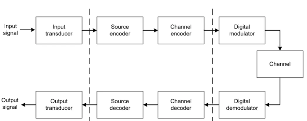
It is well-known that the functional diagram and the basic elements of a digital communication system can be illustrated by Fig.1.1 [1]. The source input-output may be either an analog (continuous-amplitude) sequence or a digital (discrete-amplitude) sequence. Whichever is the source, there is always a tradeoff between the efficiency and the reliability. For transmit-ting a digital sequence, the tradeoff would be between the spectral efficiency (bits/s/Hz) [2] and the error probability. For transmitting an analog se-quence, under the assumption of band-limited white Gaussian source, the tradeoff would be between the source-to-channel bandwidth ratio Ws/Wc
(SCBR) [21] and the mean-squared error (MSE) [22, 23], i.e., end-to-end distortion.
A distinct point between digital-source transmission and analog-source transmission is: in digital-source transmission, if the spectral efficiency is below the upper bound subject to the channel state and the transmitter knows the instantaneous CSI perfectly, the error probability would go to
1.2 End-to-end distortion 3 Input transducer Source encoder Channel encoder Digital modulator Channel Output transducer Source decoder Channel decoder Digital demodulator Output signal Input signal
Figure 1.1: Basic elements of a digital communication system
zero; whereas, in analog-source transmission, whatever good are the chan-nel condition and the system, the distortion is nonvanishing, because the entropy of a continuous-amplitude source is infinite and thus the exact re-covery of an analog source requires infinite channel capacity [16, 22–24].
In [25], Zheng and Tse studied the optimal tradeoff between the multi-plexing gain and the diversity gain (DMT) in the SNR-indicated adaptive-rate digital transmission with perfect CSIR. The transmission stage that they considered is between channel coding and channel decoding as illus-trated by Fig.1.1. For an Nt-input Nr-output Rayleigh fading channel, the
main result they obtained is
d∗(r) = (Nt− r)(Nr− r) (1.1)
in the case that the block length l ≥ Nt+ Nr− 1, where r and d are defined as
r , lim
ρ→∞
R(ρ)
log2ρ and d , − limρ→∞
Po(ρ)
log2ρ (1.2)
with ρ the average SNR, the rate R(ρ) in bits per channel use (bpcu) and outage probability Po. Therein, they assumed that the system supports that
the data rate increases with average SNR, R = r log2ρ, whereas the trans-mitter does not know the instantaneous channel rate, and thereby outage accidents happen.
Regarding end-to-end distortion, in [26, 27], Ziv and Zakai investigated the decay of MSE with SNR for analog-source transmission over a noisy single-input single-output (SISO) channel without any channel knowledge on the transmitter side. In [28,29], Laneman et al. used distortion exponent
in the asymptotic expected distortion, ∆ , − lim
ρ→∞
ED(ρ)
log2ρ , (1.3)
as a metric to compare channel diversity and source diversity for parallel channels, whose values are related to SCBR. Choudhury and Gibson pre-sented the relations between the end-to-end distortion and the outage ca-pacity for an AWGN channel [30]. Zoffoli et al. studied the characteristics of the distortions in MIMO systems with different strategies, with and without CSI [31, 32].
For tandem source-channel coding systems, assuming optimal block quan-tization and SNR-indicated adaptive-rate transmission as in [25], Holliday and Goldsmith investigated the expected end-to-end distortion for an uncor-related slow-fading MIMO channel [33–35] based on the results of [25,36,37]. They gave the bound on the total expected distortion (MSE)
ED ≤ 2−2rη log2ρ+O(1)+ 2−(Nr−r)(Nt−r) log ρ+o(log2ρ) (1.4)
where η is the SCBR. Considering the asymptotic high SNR regime, they proposed that r should satisfy
∆∗sep= (Nr− r)(Nt− r) = 2rη + o(1) (1.5)
where ∆∗
sep is the optimum distortion exponent for tandem source-channel
coding systems. The explicit expression of ∆∗
sep is given by Theorem 2
in [38], ∆∗sep(η) = 2(jd∗(j − 1)) − (j − 1)d∗(j) 2 + η(d∗(j − 1) − d∗(j)) , η ∈ · 2(j − 1) d∗(j − 1), 2j d∗(j) ¶ (1.6) for j = 1, . . . , Nmin. Note that Nmin= min{Nt, Nr}.
In [38,39], assuming an uncorrelated slow-fading channel, the transmitter perfectly knows the channel information and joint source-channel coding, Caire and Narayanan derived the optimum distortion exponent
∆∗(η) = NXmin i=1 min ½ 2 η, 2i − 1 + |Nt− Nr| ¾ (1.7)
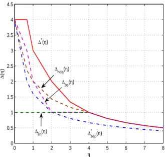
which is larger than ∆∗sep as Fig.1.2 and Fig.1.3 shows. Concurrently, the same result as (1.7) was also provided by Gunduz and Erkip [40, 41].
1.2 End-to-end distortion 5 0 1 2 3 4 5 6 7 8 0 0.5 1 1.5 2 2.5 3 3.5 4 4.5 η ∆ ( η ) ∆* (η) ∆hda(η) ∆* sep(η) ∆lin(η) ∆hda(η) ∆bs(η)
Figure 1.2: Distortion exponents for Nt= Nr= 2 case
0 1 2 3 4 5 6 7 8 0 1 2 3 4 5 6 7 8 η ∆ ( η ) ∆* (η) ∆* sep(η) ∆lin(η) ∆hda(η) ∆bs(η)
The derivation ways of Caire-Narayanan and Gunduz-Erkip are quite similar. Both are extensions of the outage probability analysis in [25] and based on the expression of MIMO channel mutual information in bpcu [42]
I = log2 ¯ ¯ ¯ ¯INr×Nr+ ρ NtHH † ¯ ¯ ¯ ¯ , (1.8)
the rate-distortion function for a white Gaussian source [16]
D(Rs) = 2−2Rs, (1.9)
and Shannon’s rate-capacity inequality for outage-free transmission [23]
Rs≤ Rc. (1.10)
The optimum distortion exponent can be a performance objective for analog-source transmission systems. As seen in Fig.1.2 and Fig.1.3, the distortion exponent ∆hda(η) of the hybrid digital analog (HDA) joint cod-ing scheme for MIMO systems proposed by Narayanan and Caire [38, 43] achieves the distortion exponent upper bound when η ≥ 2Nmin (a stricter
bandwidth compression case). Narayanan and Caire’s HDA scheme is an extension to the MIMO case of Mittal and Phamdo’s work [44]. The dis-tortion exponent ∆bs(η) of broadcast (superposition) scheme with varying
power and rate allocation proposed by Bhattad et al. [45, 46] achieves the distortion exponent upper bound when η ≥ 2Nmin/(|Nt− Nr| + 1). A simi-lar broadcast scheme in [41, 47] is a special case of [45, 46] when Nmin = 1.
By simple linear analog schemes, when η ≤ 2Nmin, the distortion exponent
∆lin(η) is always one and achieves the optimum distortion exponent when η = 2Nmin. When η > 2Nmin, the linear analog approach is infeasible.
Note that, although the distortion exponent upper bound is derived un-der the assumption that CSIT is perfectly known [38, 39] or at least the transmitter knows the instantaneous channel capacity [40, 41], the three aforementioned optimum-exponent-achieved approaches (for specific ranges or points of SCBR) do not require any transmit side channel knowledge. Taking an insight into these approaches, we can see that all of them manage to avoid outage to assure the minimum reliability: in the HDA approach, it is done by the analog part; in the broadcast approach, it is done by suppos-ing infinite layers bearsuppos-ing different rates. Nevertheless, there is somethsuppos-ing more than the distortion exponent in the expected end-to-end distortion.
Intuitively, at high SNR, the form of the optimum asymptotic expected end-to-end distortion could be
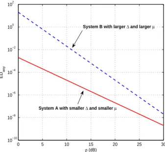
1.2 End-to-end distortion 7 0 5 10 15 20 25 30 10−10 10−8 10−6 10−4 10−2 100 102 ρ (dB) ED asy
System B with larger ∆ and larger µ
System A with smaller ∆ and smaller µ
Figure 1.4: Impact of distortion factor
where the optimum distortion factor µ∗(ρ) should satisfy the equation lim
ρ→∞
log µ∗(ρ)
log ρ = 0. (1.12)
For an analog-source transmission system, its performance at a high SNR could be measured via the asymptotic expected end-to-end distortion
EDasy= µ(ρ)ρ−∆ (1.13)
where the distortion exponent ∆ and the distortion factor µ(ρ) could be obtained analytically.
Apparently, we cannot say that a system must achieve the optimum asymptotic expected distortion ED∗asy if what it achieves is only the opti-mum distortion exponent ∆∗. Also, we cannot say that, at a practical high
SNR, the scheme with the larger distortion exponent must perform better than the other. As illustrated by Fig.1.4, in the regime of practical high SNR, the effect of the distortion factor must be taken into consideration. In other words, for practical cases, studying only the optimum distortion exponent is insufficient and giving the closed-form expression of ED∗asy is more meaningful. Using ED∗
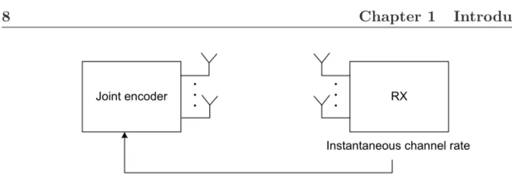
Joint encoder RX
Instantaneous channel rate
Figure 1.5: The feedback model for our end-to-end distortion analysis
µ∗, it is possible to design an analog-source transmission system performing
better than the existing systems in the regime of practical SNR. For deriving ED∗
asy, if we could obtain the analytical expression of ED∗ for any SNR,
then it would be easy to find out the optimum distortion factor µ∗(ρ) and
the optimum distortion exponent ∆∗.
1.3
MIMO channel estimate feedback
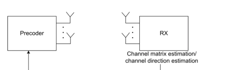
As the overview in [10], recently, precoding techniques requiring channel in-formation at the transmitter are popular for improving the performance of MIMO system, e.g., Tomlinson-Harashima precoding (THP) [48–50], trellis precoding [51], transmit matched filter [52,53], transmit zero-forcing [54,55], transmit Wiener filter [56], linear precoders [57,58], water-filling power con-trol [13, 14, 18], dirty paper coding [59] and so on. In some precoding tech-niques, such as zero-forcing beamforming, only the directions of channel vectors are required to be known at the transmitter. If the forward link and the reverse link are not reciprocal, a feedback link (as shown in Fig.1.6) can let the transmitter know the channel estimate. Since the channel gain ma-trix or vector direction is a sort of continuous-amplitude source, the feedback procedure is in fact the procedure of analog-source transmission. The feed-back approach could be in digital, analog, or hybrid digital analog (HDA). Then, our question would be again “to code, or not to code?” [60].
In digital feedback techniques, how to quantize the estimate of a MIMO channel is the key issue. In [61], D. J. Love et al. gave an overview of recent quantization techniques for limited feedback. Among them, the widely-discussed techniques are Lloyd vector quantization approach [62–64] based on Lloyd quantization algorithm [65], Grassmannnian line packing [66], and random vector quantization (RVQ) [67, 68].
1.3 MIMO channel estimate feedback 9
Precoder RX
Channel matrix estimation/ channel direction estimation
Figure 1.6: The feedback model for channel matrix or channel direction acquisition
In analog feedback techniques, feeding back the estimate of a MIMO channel is an issue of how to do analog transmission over a MIMO channel. For SISO channel, it is well known that for a white Gaussian source whose bandwidth is equal to the AWGN (real) channel bandwidth, the uncoded unquantized transmission is the optimal with respect to mean-squared error (MSE) [21, 69]. For a continuous-time AWGN channel, this optimality can be achieved by single-sideband (SSB) modulation [27, 70]. For a discrete-time AWGN channel, this optimality can be achieved by single-letter codes and MMSE receivers [71, 72]. In [72], considering downlink and uplink es-timation errors, Samardzija and Mandayam proposed an analog scheme for CSI feedback in the case of independent Rayleigh fading AWGN SISO chan-nel. Their criterion is to minimize the mean-squared error on the received channel estimate at the transmitter considering the downlink and uplink estimation errors, noise in the feedback phase, and channel distributions.
So far, many discussions on analog channel estimate feedback are focused on the scenario of vector channel for multiple users. That is, the base sta-tion has multiple antennas, each user has only one antenna, and the channel estimate feedback is from each user to the base-station. The discussion in the scenario of vector channel can be traced back to [73], where Visotsky and Madhow proposed to use analog feedback for the Rayleigh fading vec-tor channel. In [74], Thomas et al. proposed to apply analog feedback in orthogonal frequency division multiplexing(OFDM) systems over a vector channel. In [75], Marzetta and Hochwald supposed a zero-forcing receiver for the direct analog CSI feedback. Feedbacks from different users are sup-posed to be distinguished by code-division or some other ways [74, 75].
If we compare linear analog channel feedback approaches to digital feed-back approaches, the computational simpleness of linear analog approaches is obvious; whereas, digital feedback approaches cost much more
process-ing overhead. Furthermore, without external indicatprocess-ing signals such as the current SNR range, fixed-rate digital approaches cannot adapt to the chan-nel, that is, they would perform worse at relatively low SNR due to outage accidents and reach an error floor at relatively high SNR due to the in-evitable quantization error; whereas, linear analog approaches are to some extent self-adaptive to the instantaneous channel and free of outage and error floor. Also, it is hard to say that, in the analog-source transmission over a MISO/SIMO/MIMO channel subject to a strict delay limit, a rate-adaptive digital approach (with external indication) must perform better than a linear analog approach.
In [76,77], assuming that the vector channel direction feedback serves for multiuser MISO downlink zero-forcing beamforming, Caire et al. compared an analog feedback approach with an RVQ feedback approach with respect to respective rate gap upper bounds. They concluded that, with perfect channel state information at the receiver(CSIR), the RVQ digital feedback is far superior to analog when βfb > 1. Note that the feedback latency is supposed to be βfbNb channel uses with Nb the antenna number at the base station. As given in [76, 77], the rate gap upper bounds of the analog feed-back approach and the RVQ digital feedfeed-back approach with perfect CSIR are ∆RAF≤ log2 µ 1 + 1 βfb ¶ (1.14) ∆RDF≤ log2 Ã 1 + ρ 1 + (1 + ρ)βfb ! . (1.15)
Caire et al. drew their conclusion by comparing the right hand sides (RHS) of (1.14) and (1.15) [76, 77]. But, is it fair to judge actual performance by upper bound? For instance, from (1.14), we can see that there is no impact from SNR on the upper bound, however, in fact, if the CSIR is perfect and the SNR in the feedback procedure is infinitely high, the acquired CSIT via the analog approach performs nearly perfect and thus the rate gap ∆RAF
approaches zero as the value of the rate gap ∆RDFwith the digital feedback approach (the RHS in (1.15)) at infinitely high SNR while of course ∆RAF
satisfies (1.14) as zero is smaller than any positive number.
From Fig.1.2 and Fig.1.3, we can see that digital feedback could achieve a larger distortion exponent than analog feedback and thus it would cause the the resulting performance curve of digital feedback decay or increase faster. However, even though a digital approach could achieve a larger dis-tortion exponent, it may be with a much smaller disdis-tortion factor as Fig.1.4
1.4 Multi-layer transmission 11
shows.
In the case of quasi-static multi-input multi-output (MIMO) channels, space-time coding (STC) considerations with issues of diversity and spatial multiplexing arise also for analog transmission. Since the correctness of the received estimate within an allowable feedback latency deserves more concern, to find an STC to exploit the spatial diversity in linear analog transmission is of our particular interest.
1.4
Multi-layer transmission
Presently, two classes of multi-layer transmission are mainly discussed, broad-cast strategy and rateless coding.
Broadcast strategy (for single user) is the multi-layer transmission for rate adaption without feedback [46, 78–81], which stems from successive re-finement source coding [82, 83]. The framework of the broadcast strategy is as Fig.1.7 shows. Each source layer conveys the source at different rate cor-responding to respective channel realizations. All layers are superimposed subject to certain power allocation scheme for transmission. If the number of layers is infinite, it ensures that no matter how the channel realization is, at least one layer can be successfully decoded, i.e., at least some information of the source can be transmitted successfully.
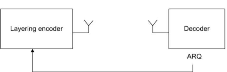
Rateless coding is the multi-layer transmission with ARQ feedback as Fig.1.8 shows. The layers are linearly combined at the transmitter and the system transmits as much of a codeword as necessary for decoding to be possible. Rateless codes for the erasure channel are known as fountain codes [84, 85], such as LT codes [86] and Raptor codes [87].
In [88–90], Erez et al. studied rateless coding for Gaussian channels with respect to transmission rate. For canceling inter-layer interference, they proposed to use random dithering to let all layered packets statisti-cally independent to each other. Then, the system benefits from multiple transmissions through summing up the average received SINR (including the interference from lower layers) of each layer at each transmission by maximum ratio combining (MRC) and subsequent successive interference cancelation (SIC) and decoding. The receiver solution is similar to that in MIMO V-BLAST [91]. The corresponding layer-time codes and the power allocation scheme have been proposed [89, 90]. If the channel is very good,
all layer packets would be successfully decoded via just one block transmis-sion; if it is bad, they would be successfully decoded after multiple block transmissions. In their schemes [89, 90], the decoder is supposed to rely on average block SINR, which has nothing to do with noise realizations but the noise variance. Namely, the block length should be long enough to let the noise during the transmission be ergodic and the block is supposed to be perfectly channel coded.
An alternative scenario is that the block length is limited and the noise experienced by one block transmission is not ergodic. In this case, the decoder would rely on the instantaneous SINR involving limited noise real-izations rather than the average SINR. Thereby, the MRC receiver proposed in aforementioned schemes would not work in this scenario. So, how to ben-efit from layer-multiplexing with HARQ feedback in that case? It would be to design a multi-layer scheme as follows: if the channel is very good, all linear combined layers could be decoded via one block transmission; if the channel is not so good, inter-layer inference could be removed or alleviated by multiple block transmissions. Such a layer-multiplexing scheme is of our interest in this thesis.
1.4 Multi-layer transmission 13 Encoder Receiver j+2 h Receiver j+1 Receiver j Receiver j-1 U n d e co d a b le d e co d a b le
Figure 1.7: Broadcast strategy for single user, i.e, multi-layer transmission for channel adaption without any feedback
Layering encoder Decoder
ARQ
Figure 1.8: Rateless coding, i.e, multi-layer reliable transmission with ARQ signaling
1.5
Thesis outline and contributions
In this thesis, we make the following contributions. These contributions are divided into three fields: 1) Optimum end-to-end distortion analysis for outage-free MIMO systems; and 2) Analog channel feedback approach; and 3) Layer-multiplexing approach for delay-restricted cases.
1. In Chapter 2, we analyze the optimum expected end-to-end distor-tion in a system over an uncorrelated MIMO channel. We derive the analytical expression of the optimum expected end-to-end distortion for any SNR and its asymptotic value for high SNR, comprised of the optimum distortion exponent and the optimum distortion factor. The results were published in
• Jinhui Chen, Dirk T. M. Slock, “Bounds on Optimal End-to-End Distortion of MIMO Links”, Proceedings of IEEE International Conference on Communications (ICC’08), Beijing, May 19-23, 2008.
and submitted as part of
• Jinhui Chen, Dirk T. M. Slock, “On Optimum End-to-End Dis-tortion in MIMO Systems”, EURASIP Journal on Wireless Com-munications and Networking, under review
2. In Chapter 3, we extend our analysis on the optimum expected end-to-end distortion to the case of correlated MIMO channels. Besides the derivations on the analytical expression of the optimum expected end-to-end distortion for any SNR and its asymptotic value for high SNR, we also prove that, with the spatial correlation matrix approaching an identity matrix, the optimum asymptotic expected end-to-end distor-tion for correlated channel converges to that for uncorrelated channel. This work was submitted as the other part of
• Jinhui Chen, Dirk T. M. Slock, “On Optimum End-to-End Dis-tortion of MIMO Systems”, EURASIP Journal on Wireless Com-munications and Networking, under review
and a part of this work was published in
• Jinhui Chen, Dirk T. M. Slock, “On Optimum End-to-End Dis-tortion of Spatially Correlated MIMO Systems”, Proceedings of
1.5 Thesis outline and contributions 15
IEEE Global Telecommunications Conferences (GLOBECOM 2008), New Orleans, Nov.30 - Dec.4, 2008
3. In Chapter 4, we study the behavior of optimum expected end-to-end distortion in the long-frame block-fading case where the time diversity is exploited by interleaving. We show the impact of time diversity on the optimum expected distortion. This work was published in
• Jinhui Chen, Dirk T. M. Slock, “Optimum end-to-end distor-tion of interleaved transmission via a Rayleigh MIMO channel”, Proceedings of IEEE 19th International Symposium Personal, In-door and Mobile Radio Communications (PIMRC 2008), Cannes, Septembre 15-18, 2008.
4. In Chapter 5, we introduce orthogonal space-time block coding (OS-TBC) into linear analog channel feedback approaches for MIMO sys-tems. We prove that the linear analog approach with OSTBC achieves the matched filter bound on received SNR and compare it with the random vector quantization (RVQ) approach and the linear analog approach with circulant STBC. Part of this work was published in
• Jinhui Chen, Dirk T. M. Slock, “Orthogonal space-time block codes for analog channel feedback”, Proceedings of IEEE Interna-tional Symposium on Information Theory (ISIT 2008), Toronto, July 6-11, 2008.
The other work that we have done related to analog channel feedback, is the comparison of the channel estimate feedback with the received signal feedback in the linear feedback approach with spatial multiplex-ing. It was published in
• Jinhui Chen, Dirk T. M. Slock, “Comparison of Two Analog Feed-back Schemes for Transmit Side MIMO Channel Estimation”, Proceedings of IEEE 19th International Symposium Personal, In-door and Mobile Radio Communications (PIMRC 2007), Athens, Septembre 3-7, 2007.
The result is that, in terms of mean squared error, the channel estimate feedback performs a little better than the received signal feedback in the supposed scenario. Since the derivation and the result are rather