O
pen
A
rchive
T
OULOUSE
A
rchive
O
uverte (
OATAO
)
OATAO is an open access repository that collects the work of Toulouse researchers and
makes it freely available over the web where possible.
This is an author-deposited version published in :
http://oatao.univ-toulouse.fr/
Eprints ID : 17085
The contribution was presented at ERTS 2016 :
http://www.erts2016.org/
To cite this version :
Bonenfant, Armelle and Carrier, Fabienne and Cassé,
Hugues and Cuenot, Philippe and Claraz, Denis and Halbwachs, Nicolas and Li,
Hanbing and Maïza, Claire and De Michiel, Marianne and Mussot, Vincent and
Parent-Vigouroux, Catherine and Puaut, Isabelle and Raymond, Pascal and
Rohou, Erven and Sotin, Pascal When the worst-case execution time estimation
gains from the application semantics. (2016) In: 8th European Congress on
Embedded Real-Time Software (ERTS 2016), 27 January 2016 - 29 January
2016 (Toulouse, France).
Any correspondence concerning this service should be sent to the repository
administrator:
[email protected]
When the worst-case execution time estimation
gains from the application semantics
∗
A. Bonenfant
2, F. Carrier
1, H. Cass´e
2, P. Cuenot
4, D. Claraz
4, N. Halbwachs
1, H. Li
3,
C. Maiza
1, M. De Michiel
2, V. Mussot
2, C. Parent-Vigouroux
1, I. Puaut
3, P. Raymond
1,
E. Rohou
5, and P. Sotin
21
Univ. Grenoble Alpes, Verimag, France, [email protected]
2Univ. Toulouse, IRIT, [email protected]
3
Universit´e de Rennes 1/IRISA, [email protected]
4Continental, [email protected]
5
Inria/IRISA, [email protected]
1
Introduction
Critical embedded systems are generally composed of repetitive tasks that must meet drastic timing constraints, such as termination deadlines. Pro-viding an upper bound of the worst-case execution time (WCET) of such tasks at design time is nec-essary to guarantee the correctness of the system. Test based methods give realistic but unsafe re-sults: they are never guaranteed to pinpoint the worst-case execution. On the contrary, static tim-ing analysis methods compute safe WCET upper bounds, but at the cost of a potentially large over-approximation.
Over-approximation will lead to an over-calibration of the application resources, and even lead to defeat the scheduling of the tasks.
In static WCET analysis, a main source of over-approximation comes from the complexity of the modern hardware platforms: their timing behav-ior tends to become more unpredictable because of features like caches, pipeline, test prediction etc. Another source of over-approximation comes from the software itself: WCET analysis may consider as potential worst-cases executions that are actually infeasible, because of the semantics of the program and/or because they correspond to unrealistic in-puts. For instance, in the automotive application (Engine Management System : EMS) of Continen-tal Corporation the modules of the application are mostly implementing generic algorithms that used calibration data for possible adaptation. Moreover a theoretical worst case scenario could correspond to an unrealistic system state like high engine speed
∗This work was funded by the Agence Nationale de la
Recherche, project W-SEPT ANR-12-INSE-0001
with low injection set point.
In the classical WCET estimation framework, the data-flow analysis is in charge of discovering infea-sible execution paths. It must at least provide con-stant bounds for all the loops in the program, oth-erwise the WCET is not even guaranteed to be fi-nite. Apart from loop-bounds, control-flow analysis usually identify simple semantics properties such as tests exclusions, that may prune infeasible execu-tion paths when computing the WCET. These so-lutions remain largely ad-hoc, and there is no clear answer to the important questions raised by infeasi-ble executions: What is the nature of such pruning properties? How to find them? (e.g., on the binary or the source code?) How to integrate them in a WCET estimation?
The goal of the W-SEPT project1
is to define and prototype a complete semantic-aware WCET esti-mation workflow. It gathers researchers in the do-main of timing and program analysis, together with an industrial partner from the real-time domain. The project mainly focuses on the semantic aspects, and thus, the pruning of infeasible paths. As far as possible, the idea is to extend and adapt the classical WCET estimation workflow, in particular, all that concerns the hardware analysis is inherited from previous work, namely the tool OTAWA2
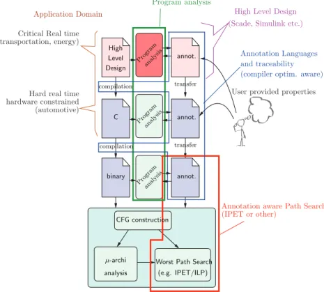
. Figure 1 depicts the proposed workflow. It re-tains the general organization of classical existing tools [16]. The bottom block is the WCET compu-tation tool itself, organized in three steps: Control-Flow graph (CFG) construction, micro-architecture analysis, and worst-path search on the CFG.
Gen-1
wsept.inria.fr
2
Application Domain
Critical Real time (transportation, energy)
Hard real time hardware constrained (automotive) annot. binary annot. annot. C High Level transfer transfer Design analy sis Program analy sis Program
(compiler optim. aware)
µ-archi analysis
Worst Path Search (e.g. IPET/ILP) CFG construction analy sis Program compilation and traceability compilation Annotation Languages
User provided properties
(Scade, Simulink etc.) High Level Design
(IPET or other)
Annotation aware Path Search Program analysis
Figure 1: Work-flow and general organization of a semantic aware WCET estimation tool erally, this last step uses the classical Implicit Path
Enumeration Technique (IPET)[9]. This tool is fed by the binary code of the program, and a set of se-mantic informations classically named annotation file, and containing at least the loop bounds.
The (binary) annotations come from the data-flow analysis (we use here the more general term of program analysis). This analysis is generally per-formed at the source level (C language most of the time) rather than the binary level. Indeed, ing C code is technically much simpler than analyz-ing binary code, but more importantly, the analy-sis often requires extra information that only the human user can provide (e.g., inputs ranges, exclu-sion, implications). The user can probably express these properties in terms of the C variables, but it would be much harder or even impossible to do it in terms of the (compiled) binary code. This two-layers description raises the well known problem of traceability of annotations when transferring infor-mation between layers.
So far, the principles depicted in Figure 1 are rather classical. The project proposes first to take into account a third layer in the design flow: the use of high-level design languages tends to become com-mon in the domains of (critical) real-time applica-tions. Classical examples of high level design tools
are Scade suite3
, used in avionics, energy or trans-portation, and Simulink/Stateflow4
widely used in control engineering systems. These high-level de-sign tools provide automatic code generation to C, which is no longer the source code, but only an intermediate code. A consequence is that user an-notations and program analysis can be expressed and performed at the design level. Once defined this third layer, the project proposes to focus on three main issues depicted by enclosing boxes in the Figure 1 :
• Program analysis, that can be performed at design, C or binary level, and may take into account information provided by the user. • Annotations and traceability between the
lan-guage levels, strongly involve the compilers: as far as possible, the compilation process should be annotation-aware, in the sense that the pro-gram transformations performed by the com-piler should be reflected as annotation trans-formations.
• (Worst) Path Search, must be adapted to take into account the (richer) kind of annotations produced by the workflow.
In this summary, we briefly introduce each step
3
www.esterel-technologies.com/products/scade-suite
4
of our workflow.
In section 2, we present how, at any stage, we can take into account annotations (from expert or automatically extracted) in order to produce a set of new ones. Then we automatically translate them when changing level, for instance loop un-rolling, while keeping their validity regarding the code transformation/compilation.
In section 3, we describe how we adapted an WCET estimation tool in order to simplify, guide and even iterate the expert annotation process and exploit new kind of annotations.
One of the industrial goal is to prevent as early as possible in the development process the timing issues. In section 4 we detail the development cy-cle of an automotive application, and how some of the proposed solutions were experimented on a case study.
2
Find and trace useful
infor-mation
In this section, we explain what kind of semantic properties may help to enhance the WCET estima-tion: where do they come from, which step of the application development do they refer to (binary, code, design), how are they transferred from one level to the next one. We consider two sources: an-notations/feedback from expert and automatically extracted properties.
In order to express most of the properties, we use (and extend) FFX, an annotation language [20]. It is an open, portable and expandable annotation format. It allows combining flow fact information from different high-level tools. It is used as an in-termediate format for WCET analysis.
2.1
Hypothesis and/or information
from Expert
Some properties are known by the expert when con-sidering the context of execution of the program: parameter domains, values for specific executions, parameters dependency... In classical tools5 6
[10] the expert input permits to reduce loop bounds. We use these precisions, called scenarios, in order to eliminate infeasible paths, in the execution con-text described by the expert.
Scenarios are used to give precisions on use cases: manual/automatic modes, context conditions like temperature, speed, height... Precisions that only
5
www.absint.com
6
www.bound-t.com
an expert can provide because related to the con-text of execution of the program/application.
For these particular cases, when the expert wants to obtain a WCET estimation, it is possible to re-duce the overestimation by taking into account con-straints and conditions of execution. In most cases, information on these constraints allow to eliminate infeasible paths or bound more accurately the num-ber of execution of certain part of the program. Indeed, when expert provides domain of certain parameters, our tools integrate these inputs and tighten our analysis.
The language FFX has been extended to express properties given by the expert. Limitations are due to the difficulties to make the expert write con-straints in FFX. In order to resolve this issue, the expert expresses constraints in C and more recently the plug-in delta, describe in Sec 3.2, provides an interface. In a further work, we will define a format allowing the expert to address constraints directly in the code via comments.
2.2
Propagation and/or extraction
of properties
2.2.1 Low-level
Looking for infeasible paths at binary level allows to benefit from the exact matching of the pro-gram with the hardware and to inject found proper-ties immediately in the WCET computation. The price is an increase of analysis time caused by the program size and the loss of expressivity im-plied by machine instructions. Consequently, exist-ing analyses either look for very simple infeasible paths [5, 15], or design a new WCET computa-tion method [15]. Our approach tries to get rid of these limitations by using SMT solvers (Satisfia-bility Modulo Theories) to generate infeasible path properties.
2.2.2 Code level
The discovery of bounds and relations on numer-ical variables is a classnumer-ical goal in program anal-ysis [3, 4], the results of which can obviously be used to restrict the set of feasible paths consid-ered in WCET evaluation. This can be helped by adding some counters to the code of the program: of course, adding a loop counter may result in find-ing a bound to this counter, and thus to the it-eration number. Moreover, adding block counters, and finding relations between these counters can re-veal subttle restrictions in the possible executions of the program. We illustrate this approach on a small example.
Program LOC #Cntr #Inv WCET init WCET fin. Improv. selector 134 14 14 1112 528 52.6% roll-control 234 25 19 501 501 0% cruise-control 234 35 31 881 852 3.3% even 82 9 8 2807 2210 23.3% rate-limiter 35 2 2 43 29 32.6% break 114 4 5 820 820 0%
Table 1: Improvement of OTAWA results with counter-based analysis at code level Consider the following program fragment where
x is not modified in block B1: x = 0; while c1 { if(x < 10){ B1: . . . } if(c2){B2: x++; . . . } }
Let’s add counters at important program points, e.g., counting the number of iterations in the loop (α) and the numbers of executions of blocks B1 (β) and B2 (γ): x = 0; α = β = γ = 0; while c1 { α++; if(x < 10){B1: β++;. . . } if(c2){ B2: γ++; x++;. . . } }
An analysis of this instrumented program using an analyser of linear relations (here, we used the tool PAGAI [7]), automatically discovers that the following relations are always satisfied at the end of the program:
γ = x , β + γ ≤ α + 10 , γ ≤ α , β ≤ α The inequality β + γ ≤ α + 10 is especially inter-esting, since it means that there are at most 10 iterations of the loop which execute both blocks B1 and B2.
Experiments: This approach has been imple-mented in a prototype tool [1], and applied in com-bination with OTAWA to several examples. Table 1 compares the results to those returned by OTAWA alone, for a set of small or medium-size programs. For each program it gives the number of lines of code, the number of introduced counters, the num-ber of useful properties found by Pagai, the WCET evaluated by OTAWA alone, the WCET evaluated by OTAWA taking into account the properties, and the percentage of improvement.
2.2.3 High-level onoff toggle high control low idle onoff toggle nom degr control toggle onoff data A B modes idle data outA low high A0 A1 A2 nom degr B0 B1 out out outA
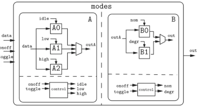
Figure 2: A typical high-level dataflow design Critical embedded systems are often designed us-ing an high level modelus-ing language, such as Scade or Simulink. The system is then automatically compiled into classical imperative code (C in gen-eral), and then into binary code (cf. Fig 1).
Figure 2 shows a typical high-level data-flow de-sign. For the sake of simplicity, it is represented as a diagram, while the actual program is actually written in Lustre [6], the academic textual language which is the ancestor of the industrial Scade lan-guage. This application consists of two sub mod-ules,
A
andB
, each of them consisting in two parts: a control part and a data processing part. The data processing part has different computation modes (e.g.A0
,A1
andA2
), controlled by a clock (e.g. idle, low and high). An important property of such a design is that these modes are exclusive: at each reaction exactly one of the modes is activated. This information, obvious at the design level, may or may not be obvious at the C or binary level: de-pending on the compilation process, the (high level) mode exclusion may result or not into structurally exclusive pieces of code. In a more subtle way, we also know, for this particular program, that it ex-ists a logical exclusion between the modes of the two sub-modules: ifA
is not idle (A1
orA2
), thenB
is necessarily in degraded mode (B1
). This property is neither structural nor obvious: it is an invariant of the infinite cyclic behavior of the application, and, as a consequence, it is almost impossible todiscover it at the low-level.
Based on these remarks, we have developed a pro-totype for discovering such properties, propagate them through the compilation process, and exploit them to enhance the WCET estimation. This pro-totype uses:
• an existing model-checker (Lesar [13]) to check the validity of properties at the Lustre level, • a traceability module that can relate high level
control variables (idle, degr etc.) to con-trol points in the C code, and then concon-trol points in the binary; this traceability is par-tial (but safe): depending on compiler opti-mizations, some relations between high and low level maybe lost. However we had good results on this particular program, even with the higher level of optimization (option -O2 of the gcc compiler)
• the OTAWA tool-chain for he binary analysis and the construction of IPET (Implicit Path Enumeration Technique) problems, together with lp-solve to solve the IPET problems. We have tried two strategies for enhancing the WCET.
Iterative algorithm:
• OTAWA is called for building an initial IPET problem, and lp-solve is called to find a first WCET control path candidate;
• according to the traceability information, the validity of this path is translated (if possible) into a logical condition on the high level vari-ables (e.g. ¬idle ∧ low ∧ nom);
• Lesar is called to check this condition; if the condition is unsatisfiable, the WCET path can-didate is proven unfeasible, the corresponding constraint is added to the IPET problem, and lp-solve is called again to find a new candidate, and so on. If the condition is satisfiable, the process stops with the current WCET. Pairwise algorithm:
• The high level code is analyzed to find a set of interesting control variables, according to a simple heuristic: any Boolean variable that control computation modes (often called the logical clocks) are likely to control big pieces of binary code, and thus, have a big influence on the computation time. In the example, the five control variables are selected.
• We “blindly” search for all possible pairwise re-lations (either exclusions or implications) be-tween these variables. For n variables, there are 4(n ∗ (n − 1)/2) = 2n(n − 1) such (poten-tial) relations (40 in the example). For each re-lations proven by Lesar, we generate the corre-sponding constraints at the binary level thanks to the traceability information; in the example,
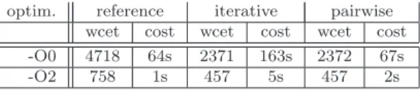
optim. reference iterative pairwise
wcet cost wcet cost wcet cost
-O0 4718 64s 2371 163s 2372 67s
-O2 758 1s 457 5s 457 2s
Table 2: Exploiting high level properties: WCET improvement and computation cost (cpu second on a i7 workstation).
5 over 40 relations are proven.
• OTAWA is called once with these constraints, and generate directly an enhanced WCET es-timation.
The whole experiment is presented in details in [14]; quantitative results are summarized and commented in Table 2 where two optimization lev-els and two strategies are experimented; enhance-ment is important for both level (-50% and -40%), and similar for both strategies. Iterative algorithm may be relatively costly, pairwise strategy has a constant overhead.
2.3
Traceability
Knowledge of semantic properties helps tighten WCET estimates. Such information is usually known at the design or source code level, whereas WCET estimation must be computed at the binary code level.
From design level to source code, we transfer the properties by tracing them in the code generator (by inserting additional comments in the C code).
From C to binary, hundreds of compiler optimiza-tions may have a strong impact on the structure of the code, making it impossible to match source-level and binary-source-level control flow graphs. This ends up in a loss of useful information. For this rea-son, the current practice is to turn off compiler opti-mizations, resulting in low average-case and worst-case performance. To safely benefit from optimiza-tions, we propose a framework to trace and main-tain flow information up-to-date from source code to machine code [8].
The transformation framework, for each compiler optimization, defines a set of formulas, that rewrite available semantic properties into new properties depending on the semantics of the concerned opti-mization. Supported semantic properties are loop bounds and linear inequations constraining the ecution counts of basic blocks. Consider, for ex-ample, loop unrolling, that replicates a loop body k times to reduce loop branching overhead and in-crease instruction level parallelism. The associated rewriting rule divides the initial loop bound by k, and introduces constraints on the execution counts
Figure 3: Impact of optimizations (-O1) on WCET. The y-axis represents the WCET with optimiza-tions, normalized with respect to the WCET with-out optimization (-O0)
of the basic blocks within the loop (see [8] for de-tails).
We implemented this traceability in the LLVM compiler infrastructure. Each LLVM optimization was modified to implement the rewriting rules cor-responding to the optimization. Semantic informa-tion is initially read from a file in the FFX for-mat [18] and then represented internally in the LLVM compiler and transformed jointly with the code transformations. Optimizations that do not modify the control flow graph can safely preserve the semantic information. Others must update the information to reflect the new graph. Note that, if a transformation happens to be too complex to trace the information, it can be disabled. This is a much better situation than the current practice which is disabling all optimizations.
Figure 3 reports the reduction of WCET esti-mates for codes from the M¨alardalen benchmark suite7
, resulting from optimizations of level O1. In this experiment, only loop bounds are traced.
The experiments first show that it is technically feasible to transform all semantic information from C code to binary without loss of information. This is shown by the fact that we can compute the WCET of all benchmarks (a single missing loop bound would make the computation impossible). Secondly, we observe that option -O1 yields an im-portant reduction of estimated WCETs: 60 % in average, and up to 86 % (optimized WCET is 14 % of unoptimized) for benchmark ludcmp, which con-tains deeply-nested loops.
7
www.mrtc.mdh.se/projects/wcet
2.4
Heuristic for targetting the
“in-teresting” properties
In order to lower the real WCET, some approaches compute the criticality of piece of codes [2] or gen-erate a static profile using probabilities for decisions at branching points [17]. The delta tool [19] aims at identifying the conditional statements that are unbalanced in terms of execution time weight (ob-tain so far by a naive account of instructions). This highlights, to the expert or the program analyzers, the parts of code where a semantic analysis or ex-pert annotation should focus to gain more accuracy on the WCET estimation.
The following experiment is detailed in [19]. In the context of the case study, the expert ini-tially provided a scenario of 30 parameter initial-izations (over 85 identified parameters). 54 ∆-conditions have been identified. 20 of the 30 pa-rameters initialized in the provided scenario appear in the list of the ∆-conditions, 18 of them exhibit-ing the highest 10 ∆-values (difference of weight between the two branches) the list. 19 of the 54 ∆-conditions have low ∆-values (218 and less than 11) and no correspondence to the parameters in the scenario. As we rely on the parameter names to appear as operands in the ∆-conditions, a pa-rameter may be linked to several ∆-conditions and vice versa.
Table 3 shows the result of WCET analysis of the module: column 1 lists the provided scenario, column 2 lists the number of specified parameters in the scenario and column 3 to 6 list the WCET estimate and improvement compared to the global WCET for an ARM7 lpc2138 platform, without and with a 1KB direct mapped data cache.
WCET analysis of the module without scenario, (1) global, reports 2553 as WCET estimate. WCET analysis of the expert-provided scenario, specify-ing 30 parameters, (2) full scenario, yields an im-provement of 5%. Rows, (3)-(6), list the estimate and gain when specifying only those parameters in-volved in the i highest valued ∆-conditions.
To validate that specifications for parameters not contained in the list of ∆-conditions have little im-pact on the estimate, we supply the 10 parame-ter initializations that do not appear in any ∆-conditions, row (7).
Summarizing, branching statement analysis iden-tified 20 of 80 parameters as important due to their high ∆-values in the list and they coincide with specified values in the expert-provided scenario. 10 parameters specified in the expert-provided sce-nario do not appear in the ∆-condition list and have almost no impact on the WCET estimate, while specifying only parameters identified in the
10 highest ∆-conditions still improves the estimate. The experiment shows that our branching state-ment analysis can help system-experts focus on the relevant parameters from the vast number of possi-ble parameters.
scenario # param. no cache
(1) global, no scenario 0 2553 gain
(2) full scenario 30 2426 5% (3) 3 highest ∆ 3 2553 0% (4) 8 highest ∆ 10 2479 3% (5) 9 highest ∆ 14 2463 3.5% (6) 10 highest ∆ 18 2448 4% (7) none of ∆ 10 2551 0.08%
Table 3: WCET computation depending on param-eters provided in scenarios
3
Integration in WCET
esti-mation tool
In this section we explain how the information ex-tracted in previous section may be exploited to en-hance the WCET estimation. We show how they are taken into account into the WCET tool and how the expert or user may interact and get feed-back from the WCET.
Scenarios and properties are given in FFX. The tool OTAWA is used to integrate all annotated property in the WCET estimation.
3.1
Exploitation through automata
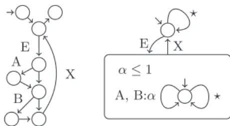
In previous works, infeasible paths properties are encoded into integer linear programming con-straints and taken into account at the last WCET estimation step [5]. In the project, we propose a general, versatile and non-intrusive process for inte-gration of the paths properties[11, 12]. This process assumes that the WCET tool internally handles CFGs and integer linear constraints, which is the case of every IPET-based WCET analysers. The internal representation of the program is extracted, improved according to the annotations and set back in the tool. The transformation relies on a novel automata formalism that can represent both the program CFG and the annotations. The transfor-mation itself is an automata product; its result is an automaton that allows only paths both existing in the original CFG and being valid with respect to the annotations. The analysis performed on the en-riched CFG delivered a WCET improvement up to 10% on the benchmarks of the WCET Tool Chal-lenge. E A B X ⋆ A, B:α α ≤ 1 E X ⋆Figure 4: Path Property Automaton
The formalism, called Path Property Automata (PPA) offers the following features:
1. State based acceptance. Like in finite state automata, one can forbid some transitions ac-cording to the history of the execution. 2. Counter based acceptance. Before being
ac-cepted, a path must satisfy numerical con-straints on the transitions it took.
3. Context of validity. The restrictions expressed using Features 1 and 2 can be subject to a con-text of validity. The notion of concon-text is ex-pressed in the formalism by hierarchical states. Figure 4 contains two PPA. On the left, the PPA isomorphic to the program CFG. On the right, the PPA reflects the annotation “in each iteration of the loop starting with E and ending with X, at most one of A or B can be taken”.
3.2
Iterative process from WCET
tool to the user
Based on the delta tool, we have developed a graph-ical tool.
Figure 3.2 shows the iterative process: given a C program and a scenario, the delta tool pro-vides annotations (in FFX format) and a list of δ-conditions. The Eclipse Delta Plugin, allows to easily visualize these δ-conditions and the parame-ters involved. The expert can re-define a scenario by visualizing the relevant parameters, obtain the consequent new unbalanced conditionals caused by the scenario, and iterate this process by refining properties on parameters in order to gain accuracy on the WCET estimate.
Figure 3.2 is an overview of the Eclipse Delta Plugin. In the center, the code is loaded. Lines corresponding to the selected δ-condition are high-lighted. A list of related parameters is provided, allowing to refine the initial value. The adapted scenario is then automatically created as a FFX file. Either it is reloaded in order to identify other relevant branchings, either it is given to Otawa in order to compute the WCET estimate.
scenario C program delta ∆ list binary FFX OTAWA WCET estimate refined scenario expert delta new ∆ list new FFX OTAWA new WCET estimate expert
Figure 5: Scenario Refining Iterative Process
Figure 6: Delta Eclipse Plug In create scenario.
4
An industrial case study
This section presents the application of some of the proposed techniques to a case study given by the industrial partner of the project, Continental. Only a part of the experiments are presented, because on one hand, the case study does not match some of the techniques — for instance, it is given in C, so the techniques devoted to higher-level code (§2.2.3) don’t apply — and on the other hand, some further experiments are still to come.
The industrial case study for the experimentation of the new WCET method is an automotive appli-cation extracted for Continental industrial portfo-lio.
The Engine Management System (EMS)
appli-cation is a complex real time appliappli-cation. The soft-ware application is an assembly of multiple sources: • C Code generated from Simulink model using model based approach. A one to one relation-ship is established between Simulink subsys-tem and C source file.
• Manual C code for other functions.
• Third party software from customer. It can be a Simulink model, a source code or an object file.
• AUTOSAR execution platform (BSW) with ei-ther code developed internally or library code bought as third party software form the mar-ket.
The software is executed on dedicated micro-controller for embedded automotive (even Engine Systems) market. It requires the use of ”specific” target compiler (unlike usual GGC or LLVM com-plier), using an internal standardized configuration options (optimization scheme, in lining, cache con-trol, memory allocation strategy ...).
The software module complexity and conse-quence on timing bound effects are managed by:
• applying encapsulation, modularity and portable design principle with focus on module reuse,
• defining generic module algorithm and use ibration data for possible adaptation. A cal-ibration is a constant ROM which is config-urable during development, and frozen for soft-ware production,
• applying MISRA-C coding rule that prevents use of dangerous coding (limitation of the use of pointer, implementing loop with bound, ), • abstracting hardware dependencies by a
Hard-ware Abstraction Layer (hardHard-ware platform and compiler independence).
Moreover, the today software is designed and imple-mented to support multi-core architecture, but first we decided to ignore this constraint in the study.
The definition and sizing of the software architec-ture is driven by resource consumption limitation and safety related constraints. The co-engineering with customer requires defining common method-ologies to be able to manage the resource such as: component split, memory control, timing control, OS and AUTOSAR services integration...
The timing resource is the one of most critical one. It needs to be estimated to organize a sound
scaling of processor resource and for the task timing allocation. So, a generic schema for task schedul-ing is defined by an architecture team and feed by the project with all software module runnable units (executable part of a software module). This is the integration work. Such configuration shall be eval-uated for the prediction of scheduling of the appli-cation and then verified by measurement on real HW target. Today schedulability design and eval-uation are based on measurement data, stored in a database. At integration time, it is necessary to evaluate the runtime of runnable units inte-grated in the Tasks, in order to properly configure the Task / the integration. Usually, this evaluation is based on the measurements done at the end of the previous V-cycle. As real measurements on bench can only be done sporadically (e.g. once/month) compared to the continuous integration work (e.g. several steps / day), the measurement data from the database becomes rapidly obsolete, and needs to be replaced by estimation. In addition, software configurations and timing measurement conditions are very difficult to standardized and therefore to compare and reuse. The actual orientation for use of heuristics for prediction is then limited in term of granularity.
In addition, the strong reuse strategy is based on reusable software components out of the hardware development context. So, the timing performance of these components needs to be provided (and reused) with an abstract timing estimation (hard-ware dependence limited). Moreover, the WCET is important to determine, but not always represents a realistic execution due to software interactions complexity.
Continental in this project aims to find a solu-tion for the early estimasolu-tion of the time execusolu-tion of software and to allow computing realistic WCET values. The sensitivity to the hardware core archi-tecture must be established to validate the results of the estimation. Of course, this approach requires to be supported by a reliable methodology, capable to support customer/client engineering exchange.
A set of software components representative of the EMS were selected to evaluate the technologies represented in the workflow (Fig 1). The expert uses the annotation concept (section 2.1) to cap-ture behavioral scenarios of the application. These scenarios match the operational conditions of ex-ecution of the software, which means real engine conditions. As an example, a theoretical worst case scenario could correspond to an unrealistic system state like high engine speed with low injection set point.
The expert is using heuristics (section 2.4) to describe the scenarios. Out of the general
condi-tions, he concentrates his effort on main effect of large branches. In particular, it is not necessary to spend engineering work on determining an active branch, if the two alternatives have an equivalent weight. The runtime estimation is refined using the propagation of the previously defined properties, in addition to the resolution of the own SW code se-mantics with the help of eventual annotations. The property propagation at C level is mostly used for this estimation.
The property propagation at low level (HW, bin, asm) has been used as verification of the estimated runtime for one specific core architecture. The high level properties propagated from Lustre language (SCADE environment not used for EMS applica-tion) is seen as requirement for the Simulink C code generation chain. The tool environment (section 3.2) is used on the selected software module to es-timate the timing execution of the runnable units of the software component.
For the selected component, the estimation of the software component timing execution is per-formed using the tool prototype environment (sec-tion 3.2). Finally, the traceability concept (sec(sec-tion 2.3) couldn’t be applied in our application due to specific target compiler used. It could lead to iden-tification of new requirement for future embedded compiler.
5
Conclusion
In this paper, we introduce the workflow imple-mented in the W-SEPT project to better integrate the application semantics. We show that seman-tic properties may be found at each language level (design, source and binary), they have to be traced through the compilation steps to be taken into ac-count in the WCET estimation. The current im-plementation already showed interesting results for benchmarks and real applications, and good feed-back from our industrial partner.
References
[1] Remy Boutonnet and Mihail Asavoae. The WCET analysis using counters - a preliminary assessment. In Proceedings of 8th JRWRTC, in conjunction with RTNS14, Versailles, France, October 2014.
[2] Florian Brandner et al. Static profiling of the worst-case in real-time programs. In RTNS, pages 101–110, 2012.
[3] P. Cousot and R. Cousot. Abstract interpreta-tion: a unified lattice model for static analysis
of programs by construction or approximation of fixpoints. In 4th ACM Symposium on Prin-ciples of Programming Languages, POPL’77, Los Angeles, January 1977.
[4] P. Cousot and N. Halbwachs. Automatic dis-covery of linear restraints among variables of a program. In 5th ACM Symposium on Prin-ciples of Programming Languages, POPL’78, Tucson (Arizona), January 1978.
[5] Jan Gustafsson et al. Automatic derivation of loop bounds and infeasible paths for WCET analysis using abstract execution. In RTSS, 2006.
[6] N. Halbwachs, P. Caspi, P. Raymond, and D. Pilaud. The synchronous dataflow pro-gramming language Lustre. Proceedings of the IEEE, 79(9):1305–1320, September 1991. [7] Julien Henry, David Monniaux, and Matthieu
Moy. Pagai: A path sensitive static analyser. Electr. Notes Theor. Comput. Sci., 289:15–25, 2012.
[8] Hanbing Li, Isabelle Puaut, and Erven Ro-hou. Traceability of flow information: Recon-ciling compiler optimizations and WCET esti-mation. In 22nd International Conference on Real-Time Networks and Systems, RTNS’14, Versailles, France, October 8-10, 2014, 2014. [9] Yau-Tsun Steven Li and Sharad Malik.
Per-formance analysis of embedded software using implicit path enumeration. IEEE Trans. on Computer-Aided Design of Integrated Circuits and Systems, 16(12), 1997.
[10] Bj¨orn Lisper. SWEET a tool for WCET flow analysis. In ISOLA, 2014.
[11] Vincent Mussot, Armelle Bonenfant, Pascal Sotin, Philippe Cuenot, and Denis Claraz. From relevant high-level properties to WCET computation improvement. In ERTS2, 2013. [12] Vincent Mussot and Pascal Sotin.
Improv-ing WCET analysis precision through au-tomata product. In 21st IEEE International Conference on Embedded Systems and Real-Time Computing Systems and Applications, RTCSA’15, Hong Kong, August 2015.
[13] P. Raymond. Synchronous program verifi-cation with lustre/lesar. In S. Mertz and N. Navet, editors, Modeling and Verification of Real-Time Systems, chapter 6. ISTE/Wiley, 2008.
[14] Pascal Raymond, Claire Maiza, Catherine Parent-Vigouroux, Fabienne Carrier, and Mi-hail Asavoae. Timing analysis enhancement for synchronous program. Real-Time Systems, pages 1–29, 2015.
[15] Vivy Suhendra et al. Efficient detection and exploitation of infeasible paths for software timing analysis. In DAC, pages 358–363, 2006. [16] Reinhard Wilhelm et al. The worst-case execution-time problem - overview of methods and survey of tools. TECS, 7(3), 2008. [17] Youfeng Wu and James R. Larus. Static
branch frequency and program profile analy-sis. In MICRO, pages 1–11, 1994.
[18] Jakob Zwirchmayr, Armelle Bonenfant, Mar-ianne de Michiel, Hugues Cass´e, Laura Kov´acs, and Jens Knoop. FFX: A portable WCET annotation language (regular pa-per). In International Conference on Real-Time and Network Systems (RTNS), Pont-` a-Mousson, 08/11/2012-09/11/2012, pages 91– 100, http://portal.acm.org/dl.cfm, novembre 2012. ACM DL.
[19] Jakob Zwirchmayr, Pascal Sotin, Armelle Bo-nenfant, Denis Claraz, and Philippe Cuenot. Identifying relevant parameters to improve WCET analysis. In WCET, 2014.
[20] Jakob Zwirchmayr et al. FFX: A portable WCET annotation language (regular paper). In RTNS, pages 91–100, 2012.