UNIVERSITÉ DE SHERBROOKE
Faculté de génie
Département de génie mécanique
DYNAMIC MODELING AND OPTIMAL CONTROL OF AN
EJECTOR BASED REFRIGERATION SYSTEM
MODÉLISATION DYNAMIQUE ET COMMANDE OPTIMALE
D'UN
SYSTÈME DE RÉFRIGÉRATION À BASE D'ÉJECTEUR
Thèse de doctorat
Spécialité : Génie Mécanique
ELHAMEH NARIMANI
Sherbrooke (Québec) Canada
November 2019
xv
I dedicate this thesis to my mother and sister, Mahin and Shima and to the memory of my late father, Reza.
MEMBRES DU JURY
Mikhail SORIN, Prof.Directeur
Philippe MICHEAU, Prof.
Co-Directeur
Alexandre GIRARD , Prof.
Rapporteur et Évaluateur
Bernard MARCOS, Prof.
Évaluateur
Brice LE LOSTEC, PhD Évaluateur
ABSTRACT
Recently, the ejector-based refrigeration system (ERS) has been widely used in the cooling industry as an appropriate alternative to the compressor-based cooling systems. However, the advantages of ERS such as the reliable operation and low operation and maintenance costs are overshadowed by its low efficiency and design complexity. In this context, this thesis presents the efforts to develop a control model enabling the ERS to operate in its optimal operational conditions. The extensive experimental studies of ERS revealed that at a fixed condenser inlet condition (𝑇, ), there exists an optimal primary stream mass flow
rate (generating pressure) that simultaneously maximizes the compression ratio (Cr) and exergy efficiency (𝜂 ) and minimizes the evaporating pressure (𝑃 ). Then, the steady state models of the heat exchangers were developed and used to investigate the influence of the increase in generating pressure on the coefficient of performance (COP) of the system and it showed that increasing the generating pressure reduces the COP, linearly. In order to predict the choking regime of the ejector and explain the reasons of observed physical phenomenon, the 1D model of a fixed geometry ejector installed within an R245fa ERS was developed. The developed model demonstrated that the ejector operates in the subcritical mode when the generating pressure is below the Cr optimum point, while it operates in critical mode at or above the optimum generating pressure. Next, a dynamic model of the ERS was built to evaluate the ERS transient response to an increase in the primary stream mass flow rate. Since the ERS dynamics is mainly dominated by the thermal dynamics of the heat exchangers, the dynamic models of the heat exchangers were developed using the moving boundary approach and connected to the developed models of the ejector and steady state models of the pump and expansion valve to build a single dynamic model of the system. The built dynamic model of an ERS was used to estimate the time response of the system in the absence of accurate experimental data of the system’s dynamics. Finally, a control model was designed to drive an ERS towards its optimal operation condition. A self-optimizing,
ii ABSTRACT
model-free control strategy known as Extremum seeking control (ESC) was adopted to minimize 𝑃 in a fixed condenser thermal fluid inlet condition. The innovative ESC model named batch phasor ESC (BPESC) was proposed based on estimating the gradient by evaluating the phasor of the output, 𝑃 , in batch time. The simulation results indicated that the designed BPESC model can seek and find the optimum 𝑃 with good performance in terms of predicting the steady state optimal values and the convergence rates.
Keywords: Ejector based refrigeration system, dynamic modeling, control strategy, Extremum seeking control, discrete time, batch phasor extremum seeking control
RÉSUMÉ
Récemment, le système de réfrigération à éjecteur (SRE) a été largement utilisé dans l'industrie du refroidissement en tant que solution de remplacement appropriée aux systèmes de refroidissement à compresseur. Cependant, les avantages du SRE, tels que le fonctionnement fiable et les faibles couts d'exploitation et de maintenance, sont éclipsés par son faible rendement et sa complexité de conception. Dans ce contexte, ce projet de recherche de doctorat a détaillé les efforts déployés pour développer une stratégie de commande permettant au système de fonctionner dans ses conditions opérationnelles optimales. Les études expérimentales approfondies du SRE ont révélé que, dans une condition d'entrée de condensateur constante (𝑇,), il existe un débit massique optimal du
flux primaire (générant une pression) qui maximise simultanément le taux de compression (Cr) et l'efficacité exergétique (𝜂 ), et minimise la pression d’évaporation (𝑃 ). Ensuite, les modèles à l’état d’équilibre des échangeurs de chaleur ont été développés et utilisés pour étudier l’influence de l’augmentation de la pression générée sur le coefficient de performance (COP) du système et il en ressort que l'augmentation de la pression génératrice réduit le COP de manière linéaire. Afin de prédire le régime d'étouffement de l'éjecteur et d'expliquer les raisons du phénomène physique observé, le modèle 1D d'un éjecteur à géométrie fixe installé dans un système SRE R245fa a été développé. Le modèle développé a démontré que l'éjecteur fonctionne en mode sous-critique lorsque la pression génératrice est inférieure au point optimal de Cr, alors qu'il fonctionne en mode critique à une pression égale ou supérieure à la pression génératrice optimale. Ensuite, un modèle dynamique du SRE a été développé pour étudier la réponse transitoire du SRE lors d’une augmentation du débit massique du flux primaire. Puisque la dynamique du SRE est principalement dominée par la dynamique thermique des échangeurs de chaleur, les modèles dynamiques des échangeurs de chaleur ont été développés à l'aide de l'approche des limites mobiles et connectés aux modèles développés de l'éjecteur et des modèles à l'état stationnaire de la
iv RÉSUMÉ
pompe et de la vanne un seul modèle dynamique du système. En l’absence de données expérimentales précises sur la dynamique d’un système SRE, le modèle dynamique développé du SRE a été simulé numériquement pour étudier sa réponse temporelle. Enfin, une stratégie de commande extrêmale (ESC) a été élaboré pour régler automatiquement le SRE à ses conditions de fonctionnement optimales, c’est-à-dire pour trouver la vitesse de la pompe qui minimise la pression 𝑃 dans des conditions d'entrée de condenseur fixes. Afin de proposer une ESC implémentable en temps discret sur une installation réelle sujette à un bruit de mesure important et un traitement hors-ligne par trame, une nouvelle commande extrémale basée sur une approche par phaseur avec une procédure de traitement de signal par trame (BPESC) a été développée et simulée avec le modèle numérique. Les résultats de la simulation ont indiqué que le modèle BPESC peut trouver la vitesse optimale de la pompe avec de bonnes performances en termes de précision et de vitesse de convergence.
Mots clés: Système de réfrigération à éjecteur, modélisation dynamique, stratégie de commande, commande extrêmale, temps discret, phaseur, optimisation
Acknowledgments
I would like to offer my sincere gratitude to my supervisor, Prof. Mikhail Sorin and my co-supervisor, Prof. Philippe Micheau, for his great wisdom, expert guidance, extensive encouragement and constructive criticism during my PhD at the University of Sherbrooke. I am very grateful to all of those who I have had the pleasure to work with during this research project. I would like to thank Dr. Hakim Nesreddine for his assistance with laboratory work, for extended discussions during preparation of journal papers, and for his willingness to help in every possible way.
I would like to thank all my friends in Canada: Yulia, Alireza, Ghofrane, Bahar and Samaneh for their love, laughter, encouragement, and understanding.
vi TABLE OF CONTENTS
TABLE OF CONTENTS
ABSTRACT ... I RÉSUMÉ ... III ACKNOWLEDGMENTS... V TABLE OF CONTENTS ... VI LIST OF TABLES ... IX LIST OF FIGURES ... XI CHAPTER 1 INTRODUCTION ... 1 1.1. GENERAL BACKGROUND ... 11.2. OBJECTIVES AND SCOPES ... 3
1.3. STATEMENT OF ORIGINALITY ... 4
1.4. ORGANIZATION OF THE DISSERTATION ... 4
CHAPTER 2 LITERATURE REVIEW ... 7
2.1. PRINCIPLE OF AN EJECTOR’S OPERATION ... 7
2.2. PRINCIPLES OF THE DYNAMIC MODELING ... 17
2.3. PRINCIPLES OF CONTROL MODELS ... 20
2.4. NOMENCLATURE ... 26
CHAPTER 3 NUMERICAL STUDY OF THE INFLUENCE OF THE PRIMARY STREAM PRESSURE ON THE PERFORMANCE OF THE EJECTOR REFRIGERATION SYSTEM BASED ON HEAT EXCHANGER MODELING ... 27
3.1. ABSTRACT ... 28
3.2. INTRODUCTION ... 29
3.3. MODELING ... 30
3.4. RESULTS AND DISCUSSION ... 35
3.4.1. Effect of the Primary Flow Pressure on Heat Transfer ... 35
3.4.2. Effect of the Primary Flow Rate on the Exergy Efficiency (𝜂𝐼𝐼) of the ERS ... 38
3.5. CONCLUSIONS ... 40
3.6. ACKNOWLEDGMENT ... 41
xv
CHAPTER 4 NUMERICAL AND EXPERIMENTAL INVESTIGATION OF THE INFLUENCE OF GENERATING PRESSURE ON THE PERFORMANCE OF A ONE-PHASE EJECTOR INSTALLED WITHIN AN R245FA REFRIGERATION CYCLE ... 43
4.1. ABSTRACT ... 45
4.2. INTRODUCTION ... 46
4.3. EXPERIMENTAL SETUP ... 48
4.4. EXPERIMENTAL ANALYSES ... 52
4.4.1. Statistical analyses ... 52
4.4.2. Spectral analyses of the signals ... 53
4.5. MODELING OF THE EJECTOR... 58
4.6. RESULTS AND DISCUSSION ... 69
4.6.1. Validation ... 69
4.7. CONCLUSIONS ... 73
4.8. ACKNOWLEDGMENTS ... 73
4.9. NOMENCLATURE ... 74
CHAPTER 5 DYNAMIC MODELING OF AN R245FA EJECTOR-BASED REFRIGERATION SYSTEM ... 75 5.1. ABSTRACT ... 76 5.2. INTRODUCTION ... 77 5.3. MODEL DEVELOPMENT ... 79 5.3.1. Pump ... 80 5.3.2. Expansion valve ... 81 5.3.3. Liquid accumulator ... 81 5.3.4. Ejector ... 82 5.3.5. Heat exchangers ... 85 5.4. SOLUTION PROCEDURE ... 90
5.5. RESULTS AND DISCUSSION ... 94
5.5.1. Experimental setup ... 94
5.5.2. Model validation results ... 95
5.6. CONCLUSIONS ... 101
5.7. ACKNOWLEDGEMENTS ... 101
5.8. NOMENCLATURE ... 102
CHAPTER 6 BATCH PHASOR EXTREMUM SEEKING CONTROL OF AN R245FA EJECTOR-BASED REFRIGERATION SYSTEM ... 105
6.1. ABSTRACT ... 107
6.2. INTRODUCTION ... 107
6.3. EXPERIMENTAL SETUP ... 111
6.4. EXPERIMENTAL ANALYSES... 112
6.5. EXTREMUM SEEKING CONTROL (ESC) ... 117
6.6. THE SIMULATION OF BPESC ... 123
6.6.1. The batch processing ... 123
viii TABLE OF CONTENTS
6.7. ESTIMATION OF THE PARAMETERS OF THE BPESC ... 127
6.8. RESULTS AND DISCUSSION ... 133
6.9. CONCLUSIONS ... 136
6.10. ACKNOWLEDGMENT ... 136
6.11. NOMENCLATURE ... 137
CHAPTER 7 CONCLUSIONS AND RECOMMENDATIONS ... 139
7.1. SUMMARY AND CONCLUSIONS ... 139
7.2. LIMITATIONS AND RECOMMENDATIONS FOR FUTURE STUDIES ... 141
7.3. RÉSUMÉ ET CONCLUSIONS ... 143
7.4. LIMITES ET RECOMMANDATIONS POUR LES ÉTUDES FUTURES ... 146
CHAPTER 8 APPENDIXES ... 148 8.1. APPENDIX A ... 148 8.2. APPENDIX B ... 149 8.3. APPENDIX C ... 150 8.4. APPENDIX D ... 150 8.5. APPENDIX E ... 152 REFERENCES ... 155
LIST OF TABLES
Table 2-1. Temperature range and characteristics for industrial waste heat sources ... 7
Table 2-2. Nomenclature ... 26
Table 3-1: Governing equations in the heat exchangers ... 32
Table 3-2: Nomenclature... 41
Table 4-1: Constant parameters used in the ejector model ... 69
Table 4-2: Validation of the thermodynamic model of the ejector with experimental data ... 70
Table 4-3: The secondary stream choking test based on mass flux and Mach number comparison 72 Table 4-4: Nomenclature... 74
Table 5-1: The constant operation conditions ... 96
Table 5-2: The maximum relative error of the dynamic model predictions ... 97
Table 5-3: Nomenclature... 102
Table 6-1: The constant operation conditions ... 112
Table 6-2: BPESC controller parameters ... 133
Table 6-3: The BPESC performance for various initial conditions with noise ... 134
LIST OF FIGURES
Figure 2-1: Schematic representation of the ERS and P-h diagram [1] ... 8
Figure 2-2: Schematic diagram of the ejector ... 9
Figure 2-3: Operational modes of an ejector [10] ... 11
Figure 2-4: Temperature-entropy charts for the three types of working fluids [15] ... 12
Figure 2-5: Variation of the suction pressure against condenser pressure[22] ... 15
Figure 2-6: Variation of COP with condenser pressure a) at different boiler temperatures b) at different evaporator temperatures [23] ... 15
Figure 2-7: Variation of the suction pressure and primary fluid mass flow rate with the vapor-generator temperature [27] ... 16
Figure 2-8: Measured and experimental ejector performance map[29] ... 16
Figure 2-9: block diagram of ESC strategy for a static map [91] ... 24
Figure 3-1: Schematic representation of an ejector refrigeration circle ... 31
Figure 3-2: (a) Heat transfer along the three zones of the generator (b) thermal plan of both sides 33 Figure 3-3: (a) Heat transfer diagram along the three zones of condenser (b) thermal plan of both sides ... 34
Figure 3-4: (a) Heat transfer diagram along the evaporator’s two zones (b) thermal plan of both sides ... 34
Figure 3-5: Variation of the COP the primary flow pressure ... 35
Figure 3-6: Variations of Qe and Qg with the primary flow pressure ... 36
Figure 3-7: Variations of UA in the generator (UAg) and evaporator (UAe) with the primary flow pressure ... 37
Figure 3-8: Variations of ∆Tlmtd in the generator (g) and evaporator(e) with the primary flow pressure ... 37
Figure 3-9: Variation of the Secondary Stream Pressure (Pe) with the primary stream pressure (Pg) ... 38
Figure 3-10: Effect of the primary flow pressure on the exergy efficiency ... 40
xii LIST OF FIGURES
Figure 4-2: The dimensions (mm) of the applied ejector in ERS ... 51
Figure 4-3: Schematic view of the measurements’ locations in the experimental setup ... 51
Figure 4-4: Histogram plots and results of Kstest for a) ps b) Cr at pP=483.71Kpa, mP=0.33 Kg/s, TC, i = 20℃ ... 52
Figure 4-5: The time evolution and spectral analyses of a) Qeb) ps c) msd) Cr at Tdist=257s, pP=483.71 Kpa, TC, i = 20℃ ... 56
Figure 4-6: The variation of filtered parameters with time at pP = 483.71 kPa, mP = 0.33 kg/s, TC, i = 20℃ ... 57
Figure 4-7: Experimental variation of a) Cr b) ps with pP ... 58
Figure 4-8: Schematic of the modeled ejector ... 59
Figure 4-9: The ejector model flowchart ... 68
Figure 4-10: Variation of Cr b) ps versus the generating pressure using the developed model ... 72
Figure 5-1: Schematic representation of the ERS setup and its P-h diagram ... 80
Figure 5-2: Schematic of the modeled ejector ... 82
Figure 5-3: The ejector model flowchart ... 85
Figure 5-4: The simplified plate heat exchanger ... 85
Figure 5-5: Schematic representation of heat exchangers model ... 87
Figure 5-6: Physical parameters coupling of ERS ... 92
Figure 5-7: ERS dynamic model flowchart ... 93
Figure 5-8: Schematic view of the measurements’ locations in the experimental setup of ERS ... 94
Figure 5-9: Heat exchangers model validation based on pressure for step change of pump speed .. 98
Figure 5-10: Heat exchangers model validation based on outlet enthalpies for step change of pump speed ... 99
Figure 5-11: Variations of primary stream mass flow rate and Er with the step change of the pump speed using the model ... 100
Figure 6-1: a) Schematic representation of the ERS setup b) its P-h diagram ... 111
Figure 6-2: Ejector performance curve at Tg, i = 80℃, Te, i = 20℃, mP = 0.37kg/s... 114
Figure 6-3: a) Variations of COP and b) ηII with an increase in N ... 116
Figure 6-4: Variation of a) Cr b) Pe c) Te, o with increasing N ... 117
Figure 6-5: Principles of the classic ESC ... 119
Figure 6-6: Effect of the dither on the static map ... 121
Figure 6-7: Block diagram of discrete time phasor Extremum seeking control ... 123
xv
Figure 6-9: The BPESC convergence time of Pe, m[k] without noise for three initial values of a) N0[0] = 1530rpm b)N0[0] = 1570rpm and c) N0[0] = 1660rpm ... 130
Figure 6-10: The influence of an increase in Ad on a)N0[k], b)g(N0[k]) and c) Pe, m[k] ... 132
Figure 6-11: The convergence of BPESC for three values of N0[0] based on a)N0 b)Pe, m... 135
Figure 8-1: Solution algorithm flowchart for the generator steady state model (Appendix A) ... 148
Figure 8-2: Solution algorithm flowchart for the condenser steady state model (Appendix B) .... 149
CHAPTER 1 INTRODUCTION
1.1. General Background
Industrial developments and the significant increase in the population and higher living standards have resulted in a growing demand of energy, and consequently the energy shortage and higher prices, as well as the global environmental issues. These issues force researchers to seek the renewable energy alternatives and approaches of utilizing low grade energies.
A remarkable portion of the energy in the residential and industrial sectors are consumed by heating, ventilation, and air conditioning (HVAC) systems and it is predicted that by mid-century countries would use more energy for cooling than heating. Indeed, the mounting demand for thermal comfort will give rise to a rapid increase in cooling system use and, consequently, electricity demand due to air-conditioning in the buildings. Application of the thermal refrigeration systems using low-grade heat would substantially reduce the energy consumption in the cooling sector.
Amongst the available technologies for the thermal refrigeration systems, the heat-driven ejector refrigeration system (ERS) is considered as a promising technology due to its reliable operation and limited maintenance needs. Furthermore, ERS is an interesting alternative to the traditional compressor-based technologies which produces the cooling effect by harvesting the waste heat from industrial processes or using renewable energy, such as solar radiation and geothermal energy. In addition, ERS has some other important advantages, including using no-moving parts in the ejector in comparison with the compressor in conventional refrigeration systems which make them vibration-free, having low initial and operational costs with long lifetime, and providing the possibility of using sustainable refrigerants [1]. According to ASHRAE, 1979 [2] the steam jet refrigerator or ejector driven
2 INTRODUCTION
refrigeration system (ERS) is first introduced by Le Blanc and Parson in 1901. However, due its low efficiency and severe degradation in performance when operating under non-idealized design conditions, ERS was not able to penetrate the market.
In fact, an ERS is made up of six components: vapor generator, ejector, condenser, evaporator, electronic expansion valve and a liquid pump. In the generator, at a constant pressure, the heat is absorbed from the external source (low grade heat source) to generate a high-pressure vapor, which is sent to ejector. The ejector also known as injector, jet pump, thermo-compressor, allows a high-pressure primary stream to accelerate and induce a low- pressure secondary stream into the primary stream path. The two streams mix through the mixing chamber and then the pressure recovery occurs in the diffuser, which enables the ejector to function as a compressor or a pump. In the condenser, the refrigerant rejects the absorbed heat (in the both evaporator and generator) and energy provided by the pump (usually negligible) to the external medium. The subcooled stream leaving the condenser is divided into two streams (primary and secondary streams). The pressure of the primary stream increases to the generating pressure using the pump and then enters the generator, whilst the secondary flow passes through an expansion valve where its pressure is reduced to the evaporating pressure. Then, it enters the evaporator, evaporates by absorbing the heat from the cooled medium and produces the cooling effect. The superheated stream leaving the evaporator is entrained by ejector [3].
However, as it was previously mentioned the ERS has some drawbacks that hold back the wide applications of such systems in the cooling industry. First, it has a low coefficient of performance (COP) in comparison with the conventional compressor-based refrigeration systems. Second, ERS is more complicated than the conventional refrigerator in terms of availability of more components in the cycle, which can cause more complexity in analyzing its behavior and designing a control model. Furthermore, the performance of ERS is severely sensitive to the instability in the low-grade heat resource [4]. Thus, the comprehensive numerical and experimental studies of ERS are required in order to improve its energy efficiency and define the optimal operation conditions.
3
There are many studies in the literature investigating the impacts of different factors on the performance of both the conventional and ejector-based refrigeration systems. However, despite the tremendous work in the area of ejectors, there is still a huge gap in the studies adopting the systemic approaches to develop the dynamic and control models for ERSs.
Hence, this PhD research project aligns with this objective to fill the literature gap in this regard. The current document will present the results of an extensive study on the development of a control model for an ERS. First, the optimal operation conditions of an ERS was investigated in terms of performance indicators including COP, Compression ratio (Cr) and the exergy efficiency (𝜂 ) using the experimental studies. It was found out that there is an optimum generating pressure in a fixed condenser inlet condition which could simultaneously maximize the Cr and 𝜂 and minimize the evaporating pressure (𝑃 ).
The new 1D thermodynamic model of the ejector was developed to explain the reasons of this phenomenon in the ejector. The unique feature of this model was related to the method it used to recognize choking regime inside the ejector. The developed model demonstrated that the ejector operates in either the critical or the sub-critical conditions using the secondary mass flux comparison with its maximum value in the hypothetical throat. Furthermore, the steady state model of the heat exchangers was developed to determine the impact of increasing the generating pressure on the COP and 𝜂 .
Then, the dynamic model of the ERS based on the moving boundary approach of heat exchangers was developed and validated with experimental data. The equations of the developed dynamic model of ERS was solved in MATLAB. At the end, a novel scheme of Extremum seeking control strategy (ESC) named batch phasor ESC was proposed to develop a control model for an ERS. The systems’ dynamics was included in in the batch phasor ESC using developed dynamic model of the ERS.
1.2. Objectives and Scopes
Regarding the need for improving the efficiency of ERS by designing an optimal control model, the present study aimed mainly at responding the following question:
4 INTRODUCTION
How to develop a control strategy to optimize the performance of ERS?
To achieve the main objective of this study explained by the research question, the following steps should be followed:
Performing the experimental analyses of an ERS to identify the optimal operation conditions
Developing the numerical steady state models of the ejector and heat exchangers within an ERS to predict the optimal operation conditions of ERS
Developing of a dynamic model of an ERS based on th moving boundary approach of the heat exchangers
Designing a control model using Extremum Seeking Control strategy (ESC) to optimize the performance of the ERS
1.3. Statement of originality
To the best of authors’ knowledge, this study is one of the first studies introducing an optimal control model for an ERS. The first dynamic model of ERS was also developed in this work. Furthermore, the novel Extremum seeking control named as batch phasor Extremum seeking control was proposed in this PhD research project which can be easily applied on the other systems with large and even variable phase lags. The author believes the control and dynamic models presented herein, along with findings of the experimental studies of the ERS, would form a comprehensive guideline for designing the more efficient ERSs.
1.4. Organization of the Dissertation
The present thesis consisted of 7 chapters:
CHAPTER 1 provides an outline of the thesis with a brief description of the contents of each chapter
5
CHAPTER 2 discusses a literature review of the main characteristics of the single-phase ejector in an ERS including the modeling and optimal operational conditions, principles of the dynamic modeling of the heat exchangers and its applications in designing the dynamic models of HVAC systems and principles of the Extremum seeking Control (ESC) in designing control models for the various HVAC systems.
CHAPTER 3 (conference article) presents a paper which was published in a conference proceeding. In this paper, the steady state moving boundary models of the plate heat exchangers were developed based on ε-NTU approach. The developed model was used to investigate the impact of the primary stream (generating) pressure on the COP and 𝜂 of an ERS. The model outputs were verified using the experimental data provided by Laboratoire des technologies de l'énergie (LTE) of Hydro-Quebec.
CHAPTER 4 (1st journal article) includes a journal article, which was
published during this doctoral study. It presents a numerical model of a single-phase ejector installed in an ERS. First, the experimental data obtained from the ERS set-up installed in LTE of Hydro-Quebec was analyzed to investigate the impact of generating pressure on Cr and evaporating pressure (𝑃 ). It was observed that there is an optimum value of the generating pressure in a fixed condenser condition that simultaneously maximizes Cr and minimizes 𝑃 . Then, a 1-D model of the ejector was developed which was able to predict the occurrence of the optimal Cr in the mentioned operational conditions.
CHAPTER 5 (2nd journal article) presents a published journal article in which
a novel dynamic model of the ERS was developed based on the moving boundary approach of the plate heat exchangers. The transient response of the model to the step change of the pump speed was validated using the experimental data provided by LTE of Hydro-Quebec.
CHAPTER 6 (3rd journal article) This chapter is a submitted journal article
6 INTRODUCTION
(ESC) for the ERS to achieve the minimum 𝑃 in the fixed condenser condition. The new scheme of ESC named batch phasor ESC was introduced in this chapter to find the optimal pump speed minimizing 𝑃 in an adaptive, model-free manner.
CHAPTER 7 presents a summary of the conclusions obtained from the experimental studies carried out in LTE and numerical studies. Furthermore, some recommendations for the future work are presented to develop the more comprehensive documentation on the subject, with fewer limitations. CHAPTER 8 includes Appendixes. Appendixes A-C show the flowcharts of
the developed steady state models of three heat exchangers in the chapter 3. Appendixes D & E represent the equations of the developed dynamic models of the condenser and evaporator in chapter 5, respectively.
The references are listed at the end of this document. All the chapters from 4 to 6 include “Avant-Propos” section, which explains abstract, the status of the articles and their contribution to this thesis in French.
CHAPTER 2 LITERATURE REVIEW
This chapter deals with a comprehensive literature review on the preceding studies investigating the refrigeration systems as well as HVAC systems. In three parts, the former work will be reviewed. In the first part, work related to the numerical and experimental studies of the ejector in the refrigeration systems as well as effective parameters of its performance will be investigated. The second part will focus on the dynamic modeling of the HVAC systems. The literature investigating the control models for HVAC systems will be outlined in the third part.
2.1. Principle of an Ejector’s operation
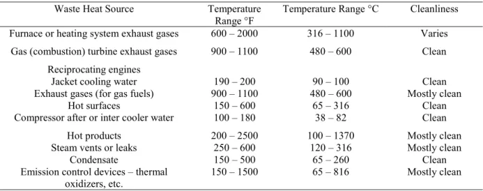
Recently, the interest in renewable and carbon free energy resources has grown among which the industrial waste heat has caught more attention due to its emission-free characteristics. The major sources of industrial waste heat are outlined in Table 2-1 [5]. Based on the report published by Thekdi and Nimbalkar [5], 20-50% of input energy to various energy systems are lost through stacks, vents and flares.
Table 2-1. Temperature range and characteristics for industrial waste heat sources
Waste Heat Source Temperature
Range °F Temperature Range °C Cleanliness Furnace or heating system exhaust gases 600 – 2000 316 – 1100 Varies
Gas (combustion) turbine exhaust gases 900 – 1100 480 – 600 Clean Reciprocating engines
Jacket cooling water 190 – 200 90 – 100 Clean Exhaust gases (for gas fuels) 900 – 1100 480 – 600 Mostly clean
Hot surfaces 150 – 600 65 – 316 Clean Compressor after or inter cooler water 100 – 180 38 – 82 Clean
Hot products 200 – 2500 100 – 1370 Mostly clean Steam vents or leaks 250 – 600 120 – 316 Mostly clean
Condensate 150 – 500 65 – 260 Clean Emission control devices – thermal
oxidizers, etc.
8 LITERATURE REVIEW
The industrial waste heat losses can be converted and recovered in some other processes like heat-driven refrigeration systems. Ejector refrigeration technology is one of those processes, which can capture the value of waste heat by cooling industrial hot streams. As this cooling system utilizes the waste heat instead of electricity produced by fossil fuel, it can reduce greenhouse gases (GHG) emissions. Ejector is an efficient device in this kind of cooling systems due to its reliability, long lifespan and low operating and maintenance costs. However, its drawbacks including low efficiency, design complexity and the fluctuations of operation particularly in off-design conditions have limited the industrial use of ejector refrigeration system. The schematic representation of an ejector-based refrigeration system (ERS) is shown in Figure 2-1.
Figure 2-1: Schematic representation of the ERS and P-h diagram [1]
The ERS performance is strongly influenced by the flow behavior inside the ejector. Figure 2-2 indicates the schematic view of a typical ejector. In fact, the ejector is a flow device and has a simple structure consisted of four parts: a nozzle, a suction chamber, a mixing chamber and a diffuser. As the primary stream accelerates through the converging-diverging motive nozzle, its speed increases to the sonic speed and leaves with supersonic speed. Then, a low-pressure region is developed due to the expansion in the primary nozzle, which induces the secondary stream from the evaporator. The secondary stream also accelerates to its sonic speed and chokes at some point inside the primary nozzle (close to the outlet of the motive nozzle). The primary and secondary flows are mixed somewhere between in the primary nozzle of the ejector (based on constant-pressure mixing theory [6]) and constant-area
9
section(based on constant-area mixing theory [6]). A pressure recovery process occurs as the mixed stream crosses a stationary shock wave and fans out through the diffuser.
Figure 2-2: Schematic diagram of the ejector
The performance of an ejector is defined by means of the global indicators:
𝐸𝑟 𝑜𝑟 𝜔 =mass flow rate of the secondary flow mass flow rate of the primary flow =
𝑚̇
𝑚̇ (2-1)
𝐶𝑟 = static pressure at diffuser exit static pressure at secondary inlet =
𝑃
𝑃 (2-2)
where 𝐸𝑟 and Cr entrainment ratio and compression ratio, respectively. Another performance indicator of the ERS is coefficient of performance (COP) which is defined as follows:
𝐶𝑂𝑃 = heat absorbed in the evaporator
thermal energy required at the generator + pump work
≈ṁ ∆h
ṁ ∆h = Er
∆h ∆h
(2-3)
It should be noted that the pump work is usually negligible. The ejector is considered as the heart of ERS where the irreversible transformations take place. Therefore, studying its features and modeling approaches would be beneficial for designing an optimal control
10 LITERATURE REVIEW
strategy. There exist abundant studies in the literature investigating the ejector and parameters influencing its performance. Some review papers were published to summarize the research efforts in the field of ejector [3][1]. There are other review articles studying the developments in the mathematical modeling and design of the jet ejectors [7][8]. Regarding the importance of the ejector modeling, many numerical and the complementary experimental work were conducted to explain impacts of different parameters on the ejector performance. Generally, the available numerical and experimental ejector studies assumed three zones for flow regime inside the ejector:
a) Nozzle section where the primary stream accelerates to its supersonic speed and consequently generates a low-pressure region at the nozzle exit plane and produces the entrainment effect to entrain the secondary fluid [8].
b) Mixing zone where the mixing of two streams has been explained with two feasible theories of constant-area mixing and constant-pressure mixing theories first proposed by Keenan et al. [6]. Huang et. al. [9] conducted a study based on the design of a “constant-pressure constant-area ejector and showed a good improvement in simulation results compared with the former models.
c) Diffuser section: the normal shock wave will usually occur before the supersonic fluid mixture enters the diffuser.
The mixed flow passes through the diffuser, and the velocity decreases to zero and the pressure increases high enough to cause discharge.
The large number of mathematical models of ejectors are one dimensional (1-D) steady state explicit equations evaluating state and operation parameters along the ejector and using the similar assumptions [10][11][12]:
- one dimension, adiabatic and steady state flow inside the ejector
- negligible kinetic energy at the inlet planes of the primary nozzle and the suction chamber and at the diffuser exit
- mass flux maximization criterion for both primary and secondary nozzles
Most of the studies in this field have used the ideal gas assumptions for their modeling, which inevitably results in the errors comparing with the reality. To remove the analytical error resulted from ideal gas assumption, Rogdakis and Alexis [13] and Chen et al. [14] used
11
the real gas relations in their simulations, which led to an improvement in the accuracy of their models. The ejector performance with fixed primary and secondary flows pressures can be explained in three operational zones shown in Figure 2-3 as explained by Huang et al model [9].
- Double-choking mode (𝑃 ≤ 𝑃 ): the primary and secondary streams are both
choked and the entrainment ratio 𝐸𝑟 is constant, i.e. 𝐸𝑟 = 𝐸𝑟
- Single-choking mode (𝑃 < 𝑃 < 𝑃 ): only the primary flow is choked, and the entrainment ratio 𝐸𝑟 changes with the backpressure 𝑃
- Back-flow mode (𝑃 ≥ 𝑃 ): both the primary and secondary flows remain unchoked and the secondary flow is reversed.
Figure 2-3: Operational modes of an ejector [10]
There exist three main factors mainly influence the performance of ejector and consequently the performance of an ERS including properties of working fluid, ejector geometry and operation conditions which have been widely investigated in the literature.
- Working fluid:
The product of the latent heat and mass flow rate of the refrigerant defines the system capacity. Thus, the higher latent heat for a given capacity, the lower mass flow rate, the less pumping energy and pipes’ size, and generally the less overall cost is required to run the cycle. In addition, the environmentally friendly and inexpensive refrigerants are preferable
12 LITERATURE REVIEW
working fluids in the refrigeration systems. According to a research carried out by Chen et al. [15] the working fluids of the refrigeration systems can be categorized into three groups based on the slope of the vapor saturation curve on the Temperature-entropy diagram (dT/ds): dry, isentropic and wet fluids. The Temperature-entropy diagram of three groups of refrigerants are shown in Figure 2-4.
Figure 2-4: Temperature-entropy charts for the three types of working fluids [15]
Dry and isentropic vapor fluids do not experience any phase change during the expansion process passing through the primary nozzle, while small droplets may be formed at the nozzle exit for a wet working fluid, which can be eliminated by superheating of inlet streams. Cizungu et al. [16] conducted a simulation for an ejector refrigerator with four various refrigerants, including R123, R134a, R152a, and R717 using the same ejector. Simulation results revealed that R134a and R512a are suitable for heat source temperature ranged from 70 °C to 85°C, while ammonia is suitable for heat source temperature more than 90 °C. The similar studies also investigated the application of various refrigerants in the refrigeration systems [17][18][19]. Cizungu et al. [17] concluded that for the same ejector geometry using the environmentally friendly working fluids such as R123, R134a, R152a and R717 (ammonia), the entrainment ratio and the system efficiency (COP) depend mainly on the ejector geometry and the compression ratio. It was also shown by Roman and Hernandez [18] that the best performance of the ejector-based refrigeration system corresponded to the system with propane as a working fluid, since it has the highest coefficient of performance
13
and its ejector has the maximum entrainment ratio value, the least area ratio value and the highest efficiency value.
Furthermore, the authors of reference [19] demonstrated a short overview of the development process and results of a small cooling capacity (1.5 kW) solar driven cooling system using a variable geometry ejector. Based on their analysis, R600a was selected as a most efficient working fluid.
- Ejector geometry:
Ejector geometry including the area ratio (AR) which is defined as the area of the constant-area part in the mixing chamber divided by the nozzle throat constant-area, primary nozzle throat diameter, nozzle exit position (NXP) and constant-area section length also effect the efficiency of ejector and the cycle performance. Chen et al [20] presented an ejector model to determine the optimum performance and to obtain the designed area ratio of an ejector in a refrigeration system. Yapıcı et al [21] studied the performance of the ejector refrigeration system using ejectors with cylindrical mixing chamber for various values of area ratio. Thongtip and Aphornratana [22] experimentally studied the impact of the primary nozzle throat diameter on the ejector performance in an R141b ejector refrigerator. They found out that use of the bigger nozzle throat, operated with lower generator temperature, is preferable and the primary nozzle exit Mach number should be as high as possible and be designed to be consistent with the heat source’s temperature for implementing the nozzle at the designed conditions.
The Nozzle Exit Position (NXP), at the front or back of the mixing chamber can influence both the entrainment ratio and pressure ratio of the ejectors. Some experimental studies as well as numerical CFD simulations indicated that moving the nozzle exit into the mixing chamber reduces the COP and cooling capacity [7] [23][24][25]. Pianthong et al [26] showed that the constant area section length has no impact on the entrainment ratio.
- Operational conditions:
It was suggested by several experimental and theoretical studies that performance of an ERS in terms of COP, Er and Cr are strongly affected by operating conditions of the evaporator, generator and condenser in the cycle.
14 LITERATURE REVIEW
Thongtip and Aphornratana [22] showed that in an R141b ERS with fixed generator temperature, the suction pressure (evaporator pressure) approximately remains constant with increasing the condenser pressure to a threshold. Then, with the further increase in the condenser pressure beyond the threshold, the evaporator pressure increases linearly (Figure 2-5). Other experimental and theoretical studies using the fixed geometry ejectors suggested that for ejectors with similar area ratios, in a given evaporator temperature, a rise in the boiler temperature would reduce COP and the cycle must operate at a higher condenser temperature. On the other hand, in a fixed boiler temperature, an increase in the evaporator temperature would raise the COP, while the condenser should work at a higher temperature, which is shown in Figure 2-6 [9] [23][27][28][29]. Figure 2-6 also illustrates that decreasing the backpressure of the ejector would result in a rise in COP as well as Er. Then, Er or COP will remain constant with further decreasing the backpressure to below a critical backpressure of the ejector. This phenomenon is closely related to the choking regime inside the ejector. The secondary flow usually reaches the sonic speed somewhere inside the nozzle section of the ejector. Increasing the back pressure of the ejector beyond its critical value will lead to the disappearance of chocking for the secondary flow, a rapid fall in the entrainment ratio and finally it will cause the ejector to stop from working.
Thongtip and Aphornratana [27] showed that there is an optimum primary fluid mass flow for a particular geometry of the ejector, which can produce the lowest evaporator temperature (or lowest suction pressure) for a specified condenser pressure. They mentioned that at this point the ejector is able to operate at a higher critical condenser pressure (Figure 2-7) [27].
15
Figure 2-5: Variation of the suction pressure against condenser pressure[22]
Figure 2-6: Variation of COP with condenser pressure a) at different boiler temperatures b) at different evaporator temperatures [23]
16 LITERATURE REVIEW
Figure 2-7: Variation of the suction pressure and primary fluid mass flow rate with the vapor-generator temperature [27]
Huang et al. [29] gathered this information in a map called ejector performance map based on which the pressure of actuating vapor (primary flow), either in design or field operation should be adjusted as close as possible to the critical back pressure to achieve the highest efficiency (Figure 2-8).
17
Despite the considerable effort made in the literature to study the performance of ejector, there is still a gap in studies investigating the ejector operation in full interaction with other system components under various conditions. Hamzaoui et al. [30] is one of pioneers in this field whom investigated the interaction between the different governing parameters and their combined effect on the ERS performance in an extensive experimental study.
2.2. Principles of the dynamic modeling
As it was shown previously many literatures performed thermodynamic analyses and steady state simulations of ERS. However, the thermodynamic study cannot directly reflect the effect of structural and operating parameters on the performance of the system. Furthermore, since the steady state simulations study the static parameters such as COP, they are unable to explain the parameters variation over the time. Dynamic modeling is an efficient approach for various purposes such as analyzing and optimizing the system performance, designing a control strategy; controlling the tuning and commissioning; and detecting the faults. It should be taken into account that each of the tasks requires a different modeling approach with various levels of accuracy. Building a dynamic modeling of ERSs is a challenging task, which should make the balance between accuracy and complexity. It was assumed by many studies [31][32] that selecting appropriate heat exchanger models is the important factor to develop a dynamic model of a vapor compression system due to the complexity of the evaporating and condensing processes in the heat exchangers. In order to build a dynamic model, first it is required to decide which parameters would have the dynamic effects and which ones can be assumed as the quasi-steady parameters.
The main issue associated with the construction of dynamic models of vapor compression systems is related to modeling instabilities caused by transients’ starts (start-stop), the transition regions in the two-phase flow and variations in thermal load. The dynamic models of vapor compression systems can be categorized into two main classes: inductive and deductive models as mentioned by Koury et al [33].
The inductive models are developed using a mathematical relation between the entry and exit variables of the system where the necessary parameters can be extracted from the
18 LITERATURE REVIEW
adequate experiments. The empirical dynamic models, which belong to the inductive model category, are quite useful due to the simple and easy model establishment and the quick identification from data. However, their application is limited to the system derived from, with their particular conditions. The examples of this approach can be found in the literature. For instance, Leducq et al. [34] developed a simple non-linear model of a vapor compression cycle to design a predictive optimal control algorithm of the system. Li et al. [35] obtained the parameters of the empirical dynamic model of a variable speed refrigeration system using the experimental data. A model of a vapor compression refrigeration system with a variable-speed compressor based on a black-box modelling technique was presented by Navarro-Esbrı et al. [36]. They used neural networks to predict the performance of the system with low cost data requirement in terms of input variables and training data. In another work conducted by Romero et al. [37] a black-box model to accurately predict the chilled water temperature dynamic response of a vapor compression chiller was proposed.
On the other hand, the deductive models, which are based on the conservation equations of mass, momentum and energy derived from physics laws, are preferred by many researchers since they provide a greater insight into the physical processes occurring under fluctuating conditions. Thus, it is believed that deductive models can be more efficient than inductive models to develop some advanced control strategies that can potentially improve control performance. Some examples of the deductive dynamic models reported in the literature are mentioned in the following section. Wang [38] developed a dynamic model of centrifugal chiller to simulate the dynamics of a seawater-cooled chilling system controlled by EMCS on-line strategies. A dynamic model for a direct expansion (DX) water-cooled air-conditioning system was presented by Shiming [39] in which the model was used to study the influence of refrigerant mass flow rate, evaporation pressure as well as air side state on the system performance. In another study conducted by Browne and Bansal [40] a simple dynamic model for vapor compression liquid chillers with modulating and on/off control was developed. The model applied the thermal capacitance approach for specific state variables to account for the dynamics of the chiller and ancillaries.
Lei and Zaheeruddin [41] built a lumped-parameter dynamic model of a water chiller refrigeration system based on the component models including evaporator, compressor,
19
condenser and a thermostatic expansion valve (TEV) and investigated the impact of control inputs such as compressor operational frequency and TEV opening fraction on the output performance of the system with the built dynamic model. Llopis et al. [42] presented a dynamic mathematical model of a shell and tube condenser operating in a vapor compression refrigeration plant.
Pfafferott and Schmitz [43] developed a Modelica based dynamic model of the CO2-refrigeration systems in which the predicted pressure parameters showed a fair agreement with the experiment while the mass flow rates differed considerably when the system was subjected to the disturbances of compressor speed step. Shi et al [44] developed the dynamic model of a transcritical CO2 supermarket refrigeration system in Dymola to study the performance of the system in the absence of experimental data.
Yao et al. [45] derived a state-space model for the vapor compression chiller by using the lumped parameter method without considering the phase change process in the condenser and evaporator thus, it was unable to simulate the dynamic responses of refrigerant states in the evaporator and condenser when subjected to ambient disturbances. Moving boundary model makes a correlative approach to describe the transient behavior of the two-phase flow heat exchanger in refrigeration system.
As Bendapudi and Braun [46] mentioned there exists two most common approaches to model heat exchangers including either discretization using the finite volume method or the implementation of a moving boundary model which both are in the deductive models category. Some studies [47] [48][49] compared the trade-off between more accurate finite volume models and computationally less expensive moving boundary models and found out that with a sufficient number of finite volumes, both approaches can achieve similar accuracies.
Therefore, as the computational effort can be crucial in dynamic optimization, the moving boundary approach has been widely used by preceding studies [50] [51] [52] [53] [54] [55] [56] [57] [58] [59] in dynamic modeling of vapor compression systems and heat pumps. The moving boundary approach (MB) divides the heat exchanger into several regions (i.e. control volumes) corresponding to the different refrigerant phases. The model parameters are
20 LITERATURE REVIEW
obtained based on the laws of conservation. Capturing the moving of the control volume boundary, the MB approach can precisely simulate the dynamic behavior of the heat exchangers.
Yao et al. [50] developed a dynamic model of a variable capacity refrigeration system based on moving boundary method which mainly focused on how to switch different MB models depend on the appearance and disappearance of phase regions. Bonilla et al. [51] built moving boundary models for evaporator and condenser which support dynamic switching between all possible flow configurations, and the simulation results were validated by experimental data. Kim et al. [52] showed a more reliable moving boundary model for heat exchangers the two-phase control volume of the heat exchanger based on which, the mean void fraction was the key parameter to calculate the fluid physical property. It was proposed by Xu and Fang [60] that the mean void fraction can be written as a function of the fluid pressure, the inlet specific enthalpy (inlet vapor quality) and the outlet specific enthalpy (outlet vapor quality) of the control volume. In the next study of Zhang and Zhang [54] implied the mean void fraction time derivative in the mass and energy equations for the evaporator, which is widely used in recent dynamic simulations [56][61].
The vapor compression systems with ejector is more complicated than the conventional vapor compression systems in terms of the system coupling and solver. Zheng et al. [61] developed a dynamic model of a transcritical CO2 ejector expansion refrigeration cycle (EERC) using mathematical models for gas cooler, evaporator and separator formulated by applying the mass and energy conservation equations.
2.3. Principles of control models
Residential and industrial air conditioning/refrigeration (AC & R) systems have extremely large start-up times and rarely operate at the steady state conditions. They are constantly trying to compensate for changes in set points and external conditions. It is evident that effective control strategies are required to drive such systems to their optimal operational conditions. There are a significant number of studies investigated various control strategies for different objective function to control AC &R systems. The considerable amount of
21
literature has dealt with the control and optimization of AC &R systems operation based on models obtained under nominal and/or calibrated conditions
Rasmussen and Alleyne developed an advanced multi-input multi-output (MIMO) control technique to control a conventional compressor-based refrigeration system for multiple objective functions of maximizing COP, exchanging efficiency for capacity when needed, controlling not only the temperature, but also humidity, and so on. They used a gain-scheduled control approach based on local models and local controllers [62]. He et al. [63] suggested a new lumped-parameter model for describing the dynamics of vapor compression cycles and studied dominating dynamic characteristics of the cycle around an operating point and concluded that single-input single-output (SISO) control technique cannot efficiently control this system.
In another study conducted by Marcinichen et al. [64] the use of a dual SISO control strategy for the simultaneous control of compressor speed and expansion valve opening was investigated and the control strategy was devised to achieve a maximum coefficient of performance (COP) within a defined values of cooling capacity. In addition, some other linear control techniques including decoupling multivariable control [65], model predictive control [66] [67], LQG control [68] [69] and robust H∞ control [70][71] [72] were used in literature to generate control models for vapor compression refrigeration systems.
Jain [73] presented a multivariable feedforward-plus-feedback control strategy to achieve the optimal cycle calculated in an offline condition. In another study carried out by Jain and Alleyne a model predictive controller (MPC) based on dynamic destroyed exergy was used to control a vapor compression refrigeration cycle [74].
However, the efficiency of model-based control strategies can be dramatically compromised in practical applications due to significant variations in the actual system characteristics and measurement errors. Recently, a class of self-optimizing controllers called “extremum seeking” has received a great deal of attention in the control literature. Extremum seeking control is mainly a form of an adaptive control where the steady-state input-output characteristic is optimized, without requiring any explicit knowledge about this input-output characteristic except that it has an extremum. Unlike the other control strategies such as
22 LITERATURE REVIEW
MPC, Extremum seeking control optimizes the system without any reference value. It has caught a great interest in the field of optimal control since extremum seeking is model free and it has proven to be both robust and effective in many different application domains. Equally being model free, there are clear limitations to what can be achieved. Perhaps paradoxically, although being model free, extremum seeking is a gradient based optimization technique and needs the efficient approaches to estimate the gradient. It means that although the extremum seeking control does not require any dynamic model of the system, the limited knowledge of the system and the efficient numerical techniques are still required to evaluate the gradient of the map . The gradient in vicinity of the optimum point of map is approximately zero.
ESC is ideal for a few reasons:
- The control model is not based on a numerical model of the system, therefore, the simplifying assumptions in developing the system’s model would not affect the accuracy of the control model.
- Unlike the other control strategies such as MPC and IMC needing the predetermined reference values, ESC is a self-optimizing control model which is not designed to peruse any reference value. As a result, the accuracy of ESC is not deteriorated by inaccuracy in the optimization method used to define the reference value of the controlled parameter.
- In order to reconstruct the state, ESC needs fewer sensors compared to MPC and IMC, and therefore the system requires less frequent maintenance for fine tuning. - ESC observes only output of the performance index (for example, Efficiency, cost,
and so on) and seeks the optimal state based on only the output signal. Then it is necessary to stabilize the system, but not necessary to know the system and the performance index forms.
However, ESC suffers from a limitation which is the requirement of a multiple time-scale separation between the system dynamics, the perturbation frequency, and the adaptation rate so as to avoid interactions and possible instabilities. This causes the convergence of ESC to be extremely slow.
23
The first notable work in this field was done by LeBlanc in 1922 [75] and also mentioned in reference [76] in which the gradient is estimated by a dither-demodulating scheme [77]. In his paper, LeBlanc explained a mechanism to transfer power from an overhead electrical transmission line to a tram car using an ingenious non-contact solution. To maintain an efficient power transfer in what is essentially a linear, air-core, transformer/capacitor arrangement with variable inductance, due to the changing air-gap, he indicated the need to adjust a (tram based) inductance (the input) to maintain a resonant circuit, or maximum power (the output). Leblanc explained a control mechanism of maintaining the desirable maximum power transfer using a method lately was known an extremum seeking solution.
Then, Some research was done in Russia in extremum seeking control field during the World War II by Kazakevich [78] [79]. Draper and Li [80] published the first English literature in extremum seeking field and detailed its performance. This paper addressed the optimization of an internal combustion engine in which the approach was perused to choose the ignition timing (the input) to achieve maximum power output. Ever since this publication, the internal combustion engines have remained a renowned application domain for extremum seeking.
Extremum seeking, like all other forms of adaptive control, was a popular research topic in the 1950s and 1960s and appeared in the literature by many different names such as extremum regulation suggested by Morosanov [81] and Ostrovskii [82], automatic optimization implied by Meerkov [83][84], optimalizing control system [85], and hill-climbing systems [86] to name but a few.
Many studies over the next three decades after the first appearance of Extremum seeking control (1970-2000), mainly focused on finding the optimal value of a static mapping and the stability issues were ignored. The first proof of extremum seeking stability based on Lyapunov stability analysis was published by Luxat and Lees [87] for a very special scheme in 1971. Despite the slow progress on the theory at the time, the practice and industrial applications of extremum seeking grew rapidly, as Astrom and Wittenmark [88] mentioned in their book in 1995 that extremum seeking was one of the most promising adaptive control methods.
24 LITERATURE REVIEW
The first rigorous proof of stability was published by Krstić and Wang [89] and its non-local stability was proofed by Tan et al. [90]. These publications sparked the renewed interests in the application of the extremum seeking control in various fields. In fact, its ability to automatically discover inputs optimizing a performance metric without requiring a model of the system distinguishes it from other nonlinear control techniques.
A block diagram of a typical Extremum seeking control (ESC) shown by Liu and Krstic [91] is illustrated in Figure 2-9.
Figure 2-9: block diagram of ESC strategy for a static map [91]
In this approach the gradient is estimated by a dither-demodulating scheme. A sinusoidal perturbation of sin (ωt) additively enters the map. Then, the measured output 𝑦 = 𝑓(𝜃) passes through a washout filter and is multiplied by the same perturbation signal, sin(ωt), to estimate the derivative (scalar gradient) 𝑓 (𝜃) at the input of the integrator. Afterwards, the estimation of 𝜃 will be updated in the direction of driving the gradient to zero. For k > 0 the ESC scheme drives 𝜃 toward the nearest local minimum of 𝑓(𝜃), whereas for k <0 the scheme converges toward the nearest maximum. Most of the extremum seeking algorithms until 1990 used the periodic excitation to explore the steady state map. Stochastic excitation started to become popular in the 1990s which can be found in some work like references [92][93][94]. Mainly there are two approaches of extremum seeking control in the literature:
- using a continuous signal to excite the steady state map and approximate the implicit gradient as described by Ariyur and Krstic [77]
25
- using a (repeated) sequence of constant probing inputs that exploit the numerical optimization methods as shown by Tee1 and Popovic [95]
Extremum seeking has been used in various fields such as compressor/thermoacoustic/jet engine instability control [96][97][98][99][100][101], electromechanical valve [102], internal combustion engines [85] [99][103][104] [105][106], flow control problems [107][108][109][110], flocking and formation control[111][112][113], human exercise machines [114], optimizing neural network/fuzzy logic controllers [115][116], maximum gain control in optical amplifiers[117], process control [118][119][120], weigh feeder control systems [121], tunable thermo-acoustic cooler [122] and so forth.
ESC has been widely used in HVAC system in the recent years due to its robust and usually fast transient performance in comparison with typical static optimization approaches. In a study carried out by Li et al. [123] an extremum-seeking control (ESC) based on self-optimizing strategy is proposed to minimize the energy consumption, with the feedback of chilled water supply command rather than the temperature and humidity measurements. In another study, Li et al. [124] applied an extremum seeking control scheme for energy efficient operation of chilled-water system, and used a Modelica based dynamic model to demonstrate the effectiveness of the proposed control strategy.
Burns et al. [125] used a model-free extremum seeking algorithm to adjust the set points of the compressor discharge temperature to optimize energy efficiency. They showed that the relationship between compressor discharge temperature and power consumption is convex (which is a requirement for this class of real-time optimization), and applied time-varying extremum seeking to drive these set points to values that minimize the power. Burns and Laughman [126] designed an energy optimizing extremum seeking controller for vapor compression systems (VCS) that automatically discovers sets of inputs that minimizes the energy consumption while the machine is in operation. This controller optimizes an input-output map (from VCS inputs to electrical energy consumed) in real-time without relying on a dynamic model of a system. Koeln and Alleyne [127] applied Extremum seeking control in a vapor compression system to find an optimal subcooling that maximizes the efficiency. For the air-source transcritical CO2 heat-pump water heater, the discharge pressure set point is taken as the input to the ESC controller, while the system COP is taken as the performance
26 LITERATURE REVIEW
index in a study conducted by Hu et al. [128]. To evaluate the proposed ESC strategy, they developed a Modelica based dynamic simulation model.
Having reviewed the literature, in three steps, I concluded that the Moving Boundary approach is the most efficient method to build a dynamic model of an ERS. Furthermore, based on the experimental findings of the optimal operational conditions of the ERS, the Extremum Seeking Control (ESC) is chosen as a control strategy to develop an optimal controller of an ERS in this PhD research project.
2.4. Nomenclature
Table 2-2. Nomenclature
Symbols Definition
P Pressure, [kPa]
𝑚̇ Mass flow rate, [kg 𝑠 ]
T Temperature, [℃] S Entropy, [kJ kg ℃] h Enthalpy, [kJKg ] subscripts c Condenser e Evaporator g Generator s Secondary p Primary i Inlet o Outlet Greek characters 𝜔 Entrainment ratio Abbreviation Cr Compression ratio
COP Coefficient of performance
ERS Ejector refrigeration system
Er Entrainment ratio
ESC Extremum seeking control
NXP Nozzle exit position
VCS Vapor compression system
1-D One dimensional
CHAPTER 3 Numerical Study of the Influence of the
Primary Stream Pressure on the Performance of the
Ejector Refrigeration System Based on Heat
Exchanger Modeling
Avant-propos
Auteurs et affiliation:
Elhameh Narimani: étudiant au doctorat, faculté de génie, département de génie mécanique, Université de Sherbrooke
Mikhail Sorin: professeur, faculté de génie, département de génie mécanique, Université de Sherbrooke.
Philippe Micheau: professeur, faculté de génie, département de génie mécanique, Université de Sherbrooke.
Hakim Nesreddine: PhD, Chercheur-Chargé de projet, Laboratoire des technologies de l'énergie, Shawinigan (Québec), Canada
Date d’acceptation : 9 Septembre 2018
État de l’acceptation : acceptée
Revue: Proceedings of ICEESD 2019- International Conference on Energy, Environment and Sustainable Development
28 Numerical Study of the Influence of the Primary Stream Pressure on the Performance of the Ejector Refrigeration System Based on Heat Exchanger Modeling
Titre français: Étude numérique de l'influence de la pression du courant primaire sur la performance du système de réfrigération à éjecteur sur la base de la modélisation d'échangeur de chaleur
Contribution au document:
Ce chapitre a étudié l’influence de l’augmentation du débit massique primaire sur la performance d’un système de réfrigération à éjecteurs en termes de COP et d’efficacité exergétique (η ) grâce à la modélisation statique des échangeurs de chaleur.
Résumé en français:
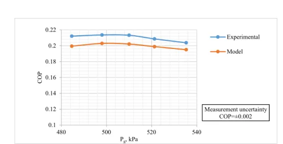
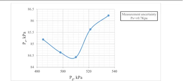
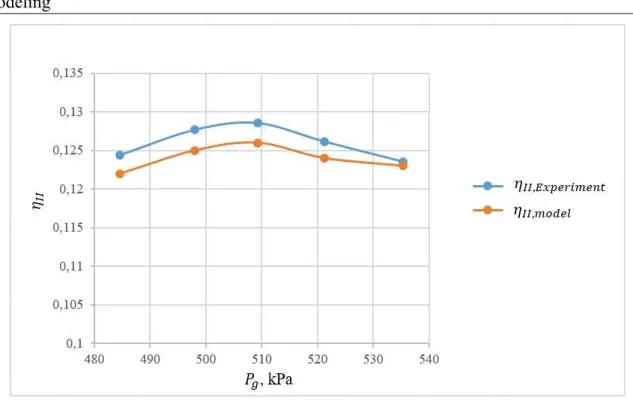
Des modèles numériques pour les échangeurs de chaleur dans le système de réfrigération à éjecteurs (SRE) ont été développés et validés avec des données expérimentales. Les modèles ont été basé sur le modèle des échangeurs de chaleur à plusieurs passes en utilisant la méthode des limites variables, qui permet d’estimer la longueur des zones, les températures de sortie des deux côtés et les charges thermiques à divers points expérimentaux. Les modèles développés ont été utilisés pour étudier l’influence de la pression primaire sur la performance d’un système R245fa en fonction de son coefficient de performance (COP) et de son efficacité exergétique (η ). Il a été illustré numériquement et a prouvé expérimentalement que l'augmentation de la pression d'écoulement primaire réduit légèrement le COP tandis que l'efficacité exergétique passe par un maximum avant de diminuer.
3.1. Abstract
Numerical models of the heat exchangers in ejector refrigeration system (ERS) were developed and validated with the experimental data. The models were based on the switched heat exchangers model using the moving boundary method, which were capable of estimating the zones’ lengths, the outlet temperatures of both sides and the heat loads at various experimental points. The developed models were utilized to investigate the influence of the primary flow pressure on the performance of an R245fa ERS based on its coefficient of performance (COP) and exergy efficiency (η ) . It was illustrated numerically and proved
![Figure 2-4: Temperature-entropy charts for the three types of working fluids [15]](https://thumb-eu.123doks.com/thumbv2/123doknet/3043346.85775/32.918.239.633.308.579/figure-temperature-entropy-charts-types-working-fluids.webp)
![Figure 2-6: Variation of COP with condenser pressure a) at different boiler temperatures b) at different evaporator temperatures [23]](https://thumb-eu.123doks.com/thumbv2/123doknet/3043346.85775/35.918.273.688.666.1004/variation-condenser-pressure-different-temperatures-different-evaporator-temperatures.webp)
![Figure 2-7: Variation of the suction pressure and primary fluid mass flow rate with the vapor-generator temperature [27]](https://thumb-eu.123doks.com/thumbv2/123doknet/3043346.85775/36.918.193.672.132.449/figure-variation-suction-pressure-primary-fluid-generator-temperature.webp)