HAL Id: pastel-00870894
https://pastel.archives-ouvertes.fr/pastel-00870894
Submitted on 8 Oct 2013HAL is a multi-disciplinary open access archive for the deposit and dissemination of sci-entific research documents, whether they are pub-lished or not. The documents may come from teaching and research institutions in France or
L’archive ouverte pluridisciplinaire HAL, est destinée au dépôt et à la diffusion de documents scientifiques de niveau recherche, publiés ou non, émanant des établissements d’enseignement et de recherche français ou étrangers, des laboratoires
Jaleh Samadi
To cite this version:
Jaleh Samadi. Development of a systemic risk management approach for CO2 capture, transport and storage projects. Other. Ecole Nationale Supérieure des Mines de Paris, 2012. English. �NNT : 2012ENMP0095�. �pastel-00870894�
MINES ParisTech
Centre de Recherche sur les Risques et les Crises
présentée et soutenue publiquement par
Jaleh SAMADI
le 14 décembre 2012Development of a Systemic Risk Management Approach for
CO
2Capture, Transport and Storage Projects
Doctorat ParisTech
T H È S E
pour obtenir le grade de docteur délivré par
l École nationale supérieure des mines de Paris
Spécialité Sciences et Génie des Activités à Risques
Directeur de thèse : Emmanuel GARBOLINO
Jury
Mme. Nancy LEVESON, Professeur, Massachusetts Institute of Technology Rapporteur
M. Laurent PERRIN, Professeur, ENSIC Rapporteur
M. Didier GRAILLOT, Dr. HDR, EMSE Examinateur
M. Marc POUMADERE, Dr., Institut Symlog Examinateur
Mme. Nadège LABAT, Ingénieur HSE Management, TOTAL Invité
M. Emmanuel GARBOLINO, Dr. HDR, MINES ParisTech Directeur de thèse
T
H
E
Curiosity has its own reason for existing.”
I gratefully acknowledge the members of my defense committee who kindly accepted to evaluate this work.
I would like to thank my supervisor, Emmanuel Garbolino, for his guidance and especially for introducing me to the fascinating field of systems thinking and system dynamics.
I also wish to express my gratefulness to Franck Guarnieri, head of Crisis and Risk research Center (CRC) of MINES ParisTech, for accepting me as a PhD candidate. I am sincerely grateful to CTSC chair for providing the financial support of the current thesis, and I truly appreciate the kind support of Denis Clodic, head of CTSC chair. Thank you to all the members of the previous evaluation committees, particularly Jean Desroches, from Schlumberger, Michel Gimenez, from Lafarge, Pascal Mallet, from Le Havre community, and the (associate) professors of MINES ParisTech who provided me with useful ideas.
Many thanks to Jean-Pierre Chéry, from Maison de le Télédétection de Montpellier , who helped me a lot to better understand the concepts of system dynamics modeling. I wish to express my sincerest thanks to R&D department of Total in Pau, working on Lacq project. I am deeply indebted to Joëlle Hy-billiot, Marc Lescanne and Samuel Lethier for the time they devoted to explain me the operational basics of Lacq pilot project and to provide me with a better comprehension of CO2storage.
I would also like to thank Jean-Luc Wybo, the director of Industrial Risk Management program (Master Maîtrise des Risques Industriels) in MINES ParisTech, for his continued advices and for introducing me as a candidate for this research project in MINES ParisTech.
I am grateful to Marc Poumadère, one of my M.Sc. professors at MINES ParisTech, who has never stopped supporting me.
some free time outside the school. I specially thank Melchior, Dalanda, Arnaud and Séverine, who also helped me to progress in learning French.
Sandrine Renaux, Myriam Perrault Lavigne and Stéphanie Garnier: thanks a lot for all your kind helps for administrative processes during the previous three years.
I might forget so many people, but I will not miss expressing my gratitude to all my friends who were always there for me. I sincerely appreciate invaluable helps of my friend, Javad Banaai, for devoting his time to read my previous reports and provide me with a great deal of useful feedback.
Finally, a unique heartfelt thanks to my dear parents, who always believed in me and provided me with lots of love and moral support along the way. Without them I could not have the opportunity to be here.
List of Figures ...9
List of Tables...12
Introduction: Context & Thesis Objectives...13
CTSC chair, financial supporter of the thesis ...14
Context...14
Thesis Objectives...17
Manuscript outline...19
Chapter 1: CTSC Technologies, Risks & Risk Management Approaches Advantages & Gaps ...21
1.1 CTSC and Climate Change ... 22
1.2 CTSC projects current status in the world... 25
1.3 CTSC Technology: An overall introduction... 27
1.3.1 CO2Capture... 27
1.3.2 CO2Transport... 32
1.3.3 CO2Storage and utilization ... 34
1.4 CTSC technology and risks... 36
1.4.1 Health and safety aspects of exposure to CO2... 36
1.4.2 CTSC: risks associated to each phase & to CTSC chain... 38
1.4.2.1 Risks associated to CO2Capture... 39
1.4.2.2 Risks associated to CO2Transport ... 40
1.4.2.3 Risks associated to CO2Storage ... 41
1.4.2.4 Risks associated to CTSC whole chain ... 42
1.5 Risk Management: concepts and evolution of approaches... 47
1.5.1 Definition of main concepts ... 47
1.5.2 Classic and modern risk analysis, assessment and management methods... 48
1.6 Risk Management and CTSC... 52
1.6.1 Available Risk Management approaches for CTSC: status and limitations... 52
1.6.1.1 CO2Capture: available Risk Management approaches... 53
1.6.1.2 CO2Transport: available Risk Management approaches... 54
Summary, Chapter 1 ... 61
Résumé (French Summary of Chapter 1) ... 62
Chapter 2: Contribution of Systems Theory and System Dynamics to CTSC Risk Management ...63
2.1 Systems Theory and System Dynamics: Introduction and key concepts... 64
2.1.1 Systems Theory ... 64
2.1.2 System Dynamics ... 66
2.2 Application fields of System Dynamics ... 74
2.3 Current dynamics of CTSC... 78
2.3.1 Dynamics of climate / atmosphere ... 79
2.3.2 Dynamics of subsurface ... 80
2.3.3 Dynamics of project ... 82
2.3.4 Dynamics of risks... 83
2.4 Contribution of Systemic Approaches and System Dynamics to study the dynamics of CTSC 84 2.4.1 Evolution of risk / safety management approaches ... 85
2.4.2 STAMP contribution to CTSC risk management... 87
Summary, Chapter 2 ... 95
Résumé (French Summary of Chapter 2) ... 96
Chapter 3: Proposed Systemic Methodology for Risk Management of CTSC projects ...97
3.1 Methodology... 98
3.1.1 Overview of the proposed methodology ... 99
3.1.2 Methodology of modeling CTSC projects safety control structure... 107
3.2 General application of the methodology: Modeling major risks affecting CTSC project progress... 110
3.2.1 First example: risk of not obtaining project permits... 110
3.2.2 Second example: risk of technology scale-up problems... 114
3.2.3 Third example: risk of public opposition... 117
3.2.4 Fourth example: risk of model and data issues ... 119
3.2.5 Fifth example: risk of financial resource shortage... 123
3.2.6 Risk interconnections and example of a regrouped model ... 126
Control Model ...133
4.1 Application of the methodology for case studies ... 134
4.1.1 First example: Barendrecht... 134
4.1.2 Second example: Lacq... 141
4.1.3 Third example: Weyburn... 144
4.2 Comparison of case studies, from context point of view ... 147
4.3 Comparison of case studies, from risk point of view ... 148
4.4 Discussions and proposed safety control structure for CTSC projects ... 157
Summary, Chapter 4 ... 168
Résumé (French Summary of Chapter 4) ... 169
Chapter 5: Conclusions, Advantages & Limits of the Methodology and Suggestions for Further Studies 171 5.1 Proposed Methodology: Overview & Advantages... 172
5.2 (Potential) Limitations of the proposed methodology ... 178
5.2.1 Lack of information on CTSC ... 178
5.2.2 Qualitative vs. quantitative approach... 179
5.2.3 Subjectivity of modeling and risk assessment ... 180
5.3 Suggestions for further studies ... 180
Summary, Chapter 5 ... 184
Résumé (French Summary of Chapter 5) ... 185
References...186
Appendixes...201
Appendix 1: Five Global Risks Categories [WEF, 2012]... 201
Appendix 2: Global Risks Landscape 2012 [WEF, 2012] ... 202
Appendix 3: Sources of industrial CO2 emissions of more than 0.1 MtCO2 per year [IPCC, 2005] ... 203
Appendix 4: Published exposure limits to CO2[Johnsen et al., 2009] ... 204
Appendix 5: Areas of concern of different CTSC stakeholders [CCP, 2012]... 205
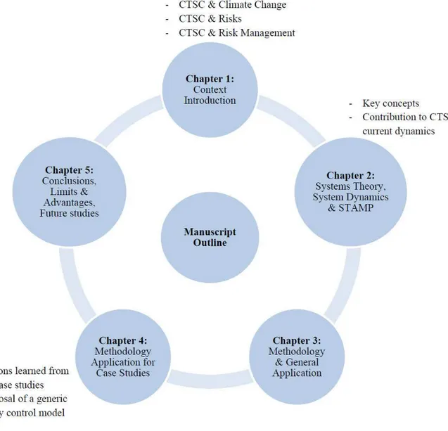
Figure I.2: Manuscript outline... 20
Figure 1.1: Key technologies for reducing CO2emissions under the BLUE Map scenario [IEA, 2010] ... 23
Figure 1.2: Possible CTSC systems [IPCC, 2005]... 24
Figure 1.3: LSIP CTSC projects by region and project phase [GCCSI, 2012b] ... 25
Figure 1.4: LSIPs by industry sector [GCCSI, 2012b] ... 26
Figure 1.5: CO2Capture technologies [IPCC, 2005] ... 27
Figure 1.6: CO2recovery by chemical absorption, Typical Process Flow Diagram [IPCC 2005] ... 30
Figure 1.7: General schemes of CO2Capture main separation processes [IPCC, 2005] ... 32
Figure 1.8: CO2phase diagram [IPCC, 2005]... 33
Figure 1.9: CO2geological storage options [GCCSI, 2011a] ... 34
Figure 1.10: Schematic risk profile for a storage project [GCCSI, 2011a]... 42
Figure 1.11: Scope of policy landscapes related to CTSC [GCCSI, 2011a]... 43
Figure 1.12: Components of Risk [Leveson, 1995] ... 47
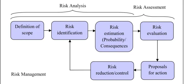
Figure 1.13: Risk Analysis, Risk Assessment and Risk Management process (adapted from [Koivisto et al., 2009]) ... 48
Figure 1.14: Basic energy model of accident [Leveson, 1995]... 49
Figure 1.15: The domino theory [Hollnagel, 2004] ... 50
Figure 1.16: Model of a sociotechnical system [Samadi & Garbolino, 2011] ... 60
Figure 2.1: Dynamic modeling process ... 68
Figure 2.2: Improved dynamic modeling process... 69
Figure 2.3: Double loop learning in the real world [Sterman, 2000] ... 71
Figure 2.4: An example of stock-flow-feedback loop structure [Dulac et al., 2007]... 72
Figure 2.7: General steps of dynamic risk analysis for an industrial plant [Garbolino et al.,
2010] ... 77
Figure 2.8: Global CO2atmospheric concentrations and temperature [GCCSI, 2011a]... 80
Figure 2.9: The circulation of water in the hydrologic system [Hamblin & Christiansen, 2004]81 Figure 2.10: The tectonic system [Hamblin & Christiansen, 2004]... 81
Figure 2.11: Summary of CO2Storage Life Cycle Phases and Milestones [CCP, 2010] ... 83
Figure 2.12: Evolution of safety management approaches (translated from [Cambon, 2007]) .. 86
Figure 2.13: Evolution of safety management approaches, an improved proposition ... 87
Figure 2.14: The sociotechnical system involved in risk management [Rasmussen & Svedung, 2000] ... 88
Figure 2.15: Model of sociotechnical system control [Leveson, 2009] ... 89
Figure 2.16: A standard control loop [Leveson, 2009] ... 90
Figure 2.17: Example of a control structure relevant to an accident analysis (Citichem) [Leveson, 2009] ... 93
Figure 3.1: Proposed methodology steps ... 99
Figure 3.2: Methodology of modeling CTSC projects safety control structure ... 107
Figure 3.3: Feedback network affecting the risk of not obtaining the required permits ... 113
Figure 3.4: Feedback network affecting the risk of technology scale-up problems... 116
Figure 3.5: Feedback network affecting the risk of public opposition... 118
Figure 3.6: Evolution of risks and knowledge during CTSC project life cycle [Koornneef et al., 2012] ... 121
Figure 3.7: Feedback network affecting the risk of model and data issues... 122
Figure 3.8: Feedback network affecting the risk of financial resource shortage... 124
Figure 3.9: Interconnections of major risks affecting CTSC projects progress ... 126
Figure 3.10: Overall feedback network of the risks presented in section 3.2 ... 127
Figure 4.3: Barendrecht safety control structure, improved model... 140
Figure 4.4: Lacq safety control structure, initial model ... 143
Figure 4.5: Location of Weyburn CO2storage field [Verdon, 2012]... 144
Figure 4.6: Weyburn safety control structure, rough model based on [CCP, 2012] ... 146
Figure 4.7: Interconnections of major risks affecting Barendrecht project progress ... 151
Figure 4.8: Interconnections of major risks affecting Barendrecht project progress, modified according to lessons learned... 152
Figure 4.9: Interconnections of major risks affecting Lacq project progress... 153
Figure 4.10: Interconnections of major risks affecting Weyburn project progress ... 155
Figure 4.11: Model of a CTSC Project SWOT Analysis ... 161
Figure 4.12: SWOT Analysis, Barendrecht Project ... 162
Figure 4.13: SWOT Analysis, Lacq Project... 163
Figure 4.14: SWOT Analysis, Weyburn Project... 163
Figure 4.15: Proposed Safety Control Structure for CTSC projects ... 165
Figure 5.1: Example of extreme risks identified by [GCCSI, 2009a] ... 175
Figure 5.2: Risk Matrix used by [GCCSI, 2009a]... 176
Figure 5.3: Integrated CTSC Risk Management methodology proposed by [Kerlero de Rosbo, 2009] ... 177
Table 1.2: Storage capacity of different reservoirs [IPCC, 2005]... 36
Table 1.3: Occupational exposure standards for CO2[IPCC, 2005]... 37
Table 1.4: Maximum and recommended level of impurities in CO2from a health and safety point of view [De Visser et al., 2008] ... 40
Table 1.5: Major risks affecting the very first phases of the project... 46
Table 1.6: Available Risk Assessment methodologies for CO2storage [Condor et al., 2011]... 56
Table 2.1: Classic Rationalism Approach vs. Systemic Approach (translated from [Durand, 2010; Le Moigne, 2006]) ... 65
Table 3.1: Overview of risks affecting CTSC project progress ... 100
Table 3.2: Risks associated to CTSC and affected project phases ... 101
Table 3.3: Nature of CTSC risks and their consequences... 104
Table 3.4: Major risks affecting the very first phases of the project... 106
Table 3.5: Summary of first example, risk of not obtaining the required permits ... 114
Table 3.6: Summary of second example, risk of technology scale-up problems ... 117
Table 3.7: Summary of third example, risk of public opposition ... 119
Table 3.8: Summary of fourth example, risk of model and data issues ... 123
Table 3.9: Summary of fifth example, risk of financial resource shortage ... 125
Table 4.1: Comparison of case studies context ... 147
Table 4.2: Comparison of risks associated to case studies... 149
Table 4.3: Principal Inadequate Control Actions leading to Barendrecht project failure ... 152
Table 4.4: Principal (Potential) Inadequate Control Actions leading to Lacq project delay or failure ... 154
Table 4.5: Principal (Potential) Inadequate Control Actions leading to Weyburn project delay or failure ... 157
CTSC chair, financial supporter of the thesis
The current thesis has been funded by CTSC chair, which is a MINES ParisTech research program on Capture, Transport and Storage of CO2(CTSC). The chair covers
eight main research areas including: CO2 capture and capture energy efficiency, CO2
Transport networks and pooled infrastructures, Risks related to CO2 geological storage,
Local and global social perception of carbon storage, Carbon economy and CTSC, Innovation and large scale diffusion of CTSC technologies, Regional scale impact assessment and Demonstration programs. Several universities, research centers, companies and local authority representatives are engaged in CTSC chair program. In MINES ParisTech, Crisis and Risk research Center (CRC), Center of Energy and Process (CEP), Center of Geoscience and CERNA (Center of Industrial Economics) are involved. Several departments of Le Havre university, Le Havre local authorities, BRGM (Bureau de Recherches Géologiques et Minières), Total, Lafarge, GDF Suez, EdF and Air Liquide are other partners of the chair[CTSC chair].
Context
Climate change has been a major concern of societies for several years. Global risks have been categorized in five groups, including economic, environmental, geopolitical, societal and technological in the latest report of World Economic Forum (WEF)[WEF, 2012]. Climate change is pointed out in two of these categories: environmental and
technological, termed as Failure of climate change adaptation and Unintended
consequences of climate change mitigation respectively. WEF raises a question whether our current safeguards are appropriate to manage emerging risks which are inherently present in our complex world; and believes that stakeholders brainstorming is essential for emerging risks management. Global risks from WEF point of view are available in Appendixes 1 and 2.
Capture, Transport and Storage of CO2 (CTSC) is one of the technologies planned to
contribute to industrial CO2emissions and climate change mitigation. CTSC consists of
a chain of processes to collect or capture a CO2 gas stream, transport the CO2 to a
storage location and inject it into that location. The most significant source of CO2
automobiles and industrial facilities. A number of specialized industrial production processes and product uses such as mineral production (cement, lime, etc.), metal production (iron and steel, aluminum, etc.) and the use of petroleum-based products can also lead to CO2emissions[EPA, 2010].
CTSC is currently a constituent of global energy policy, although there are still lots of uncertainties regarding CTSC contribution and development.
CTSC is considered as a low carbon technology along with renewable energies, nuclear, increasing energy efficiency and fuel switching. The target is to halve the current CO2
emissions by 2050 [GCCSI, 2011a]. International Energy Agency (IEA) proposes that
CTSC will reduce 19% of CO2 emissions by 2050 [IEA, 2010]. CTSC is concerned
with not only climate change and energy policies, but also industry and innovation policies[GCCSI, 2011a].
While United Nations Framework Convention on Climate Change (UNFCCC) has
emphasized on the importance and urgency of climate change concerns [UNFCCC,
2012], national policies seem to deal with several uncertainties. Canada s withdrawal from Kyoto protocol just after the last climate change conference in Durban (November 28-December 11, 2011) is an example of uncertain policies.
Perceptions of stakeholders on the effectiveness of CTSC are different. Although most of governments and industries intend to invest on the technology, others such as local
communities and NGOs are worried about long term risks and reliability of CO2
storage. CO2leakage is the most significant concern of these groups since it could lead
to risks for human beings, animals and plants as well as potable water networks.
Risk Assessment and Management are essential parts of CTSC development in order to provide answers for the uncertainties and assure the control of well-understood parts of CTSC processes.
Several studies have been carried out on risk assessment of Capture, Transport and
Storage technologies. Risks of CO2 Capture and Transport are assumed to be
well-understood. Therefore, classical methods have been usually applied for analyzing risks
of Capture and Transport subsystems. However, CO2 storage is known as a
non-engineered part of the process, dealing with various uncertainties [Koornneef et al., 2012]. Consequently, most of available risk assessment studies are focused on CO2
What is neglected in most of available approaches is that CTSC is a complex sociotechnical system for which risks could not be analyzed individually, without taking the whole context into account. Complex system is a system composed of many parts
that interact with and adapt each other. In most cases, the behavior of such systems cannot be adequately understood by only studying their component parts. This is because the behavior of such systems arises through the interactions among those parts [IRGC, 2010].A sociotechnical system is a one consists of a technical part which is in interaction with a social part.
Risks associated to CTSC are not limited to technical risks. Along with technical challenges, CTSC is faced to uncertainties concerning development up to commercial scales. At the present time, seventy four large scale integrated projects are identified in
the world. Only fourteen projects are in construction or operation phase [GCCSI,
2011a]. A number of projects have been cancelled or delayed for various reasons. Therefore, a major question about CTSC at the current scale of development is what are the factors explaining the success or failure of CTSC projects in different contexts? In order to answer this question, a systemic risk management framework is proposed based on the concepts of System Dynamics and STAMP (Systems-Theoretic Accident Model and Processes), developed at Complex Systems Research Laboratory of Massachusetts Institute of Technology.
Aside from sociotechnical complexity of CTSC system, the idea comes from systemic and dynamic characteristics of risk. Systems are regularly adapting themselves to perturbations. Nevertheless, positive feedbacks lead to system destabilization by amplifying the perturbations. So, it is important to identify feedback dynamics involved in the system in order to better anticipate when risks might emerge or be amplified
[IRGC, 2010]. In this thesis, systemic modeling is proposed as a decision making support, which provides the grounds of thinking about the components of a potentially
successful CTSC project. Each stakeholder is assumed as a controller , who is
responsible for maintaining safety constraints. Safety control structures are developed for several case studies to formalize the relations of stakeholders in maintaining safety constraints.
Thesis Objectives
The initial objective of the thesis was to develop an integrated risk analysis methodology. The purpose was to cover health and safety risks for the operators and local population as well as environmental risks. System dynamics was planned to be applied for modeling interactions of technical system, operators and decision makers. Following steps were anticipated for the work:
- Studying lessons learned from CTSC incidents and accidents - Identifying the actors of CTSC chain
- Modeling the technical system and its connections with the human and organizational parts
- Dynamic analysis of risks - Defining deviation scenarios - Consequence analysis of scenarios - Providing recommendations
The models were planned to be verified in a CTSC pilot plant.
The research question was progressively formulated as studying the performance of CTSC safety control system.
In the course of study, the objective and research question were modified for several reasons. The main reasons include:
1. CTSC integrated chain is an emerging technology for which few lessons learned are available. Publically available information on CTSC is restricted due to confidentiality issues. Therefore, gathering information on operational aspects of risk was a challenge.
2. Feedback loop is an essential concept of system dynamics which has to be integrated in system dynamics models. The models of technical system confirmed that feedback loops appear only when we consider interconnections of system variables and control variables. Studying such interconnections requires a great amount of data, which are not available for CTSC.
3. Discussions with experts of the domain led us to the conclusion that the most significant question in terms of integrated CTSC risk analysis is not the performance of CTSC safety control system from technical point of view. The actual concern is whether CTSC projects will be developed up to commercial scales.
Based on these facts, the research question formulation was modified in the final year of the thesis. Effectiveness of safety control structure is still in question. However, a broader definition of safety is taken into account. Safety is defined as the absence of
losses due to an undesired event [Leveson, 1995, p.181]. Losses in this definition include human losses, mission or goal losses, equipment or material losses and
environmental losses [Dulac, 2007, p.31]. The thesis is focused on mission or goal losses. Other kinds of failures do have impacts on mission losses.
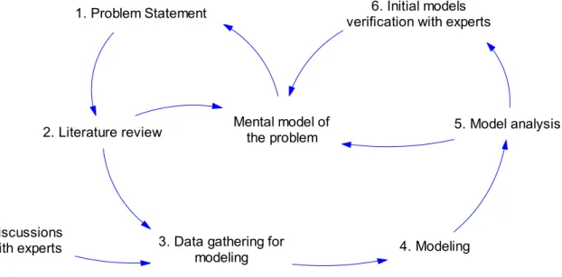
Feedback network involved in the evolution path of the thesis objectives could be illustrated in the form of a causal graph (Figure I.1). Causal graph is a key concept of system dynamics that will be introduced in chapter 2.
1. Problem Statement
2. Literature review
3. Data gathering for modeling Mental model of the problem 4. Modeling 5. Model analysis 6. Initial models
verification with experts
Discussions with experts
Figure I.1: Feedback network involved in the evolution path of thesis objective
Required data for modeling have been gathered from reviewing available literature and discussions with experts. Initial models have been developed, analyzed and verified with experts. Mental models of the modeler have been affected from and improved based on this process in the course of study. The problem has been consequently reformulated according to the new mental model. As illustrated in Figure I.1, mental model of the problem is at the heart of the evolution path and has been affected from literature review, model analysis and initial models verification with experts.
Manuscript outline
The manuscript contains five chapters.
CTSC contribution to climate change and an overview of CTSC projects current status are presented in chapter 1. Capture, Transport and Storage processes and associated risks are then reviewed. Different aspects of risk related to CTSC whole chain are introduced here, including Technical, HSE (Health, Safety and Environment), Policy/Strategy, Legal, Organizational/Human, Financial/Economic, Social and risks concerning the Project.
Afterwards, principal notions of risk management as well as traditional and latest risk management approaches are reviewed.
At the final section of chapter 1, available risk management methods for Capture, Transport and Storage subsystems and CTSC whole chain are presented. And we wrap up with the necessity of developing a systemic risk management framework for CTSC. Chapter 2 deals with how system dynamics and systemic approaches could contribute to CTSC risk management. The chapter begins with the introduction of systems theory and system dynamics. After reviewing application fields of system dynamics, dynamics involved in the current CTSC context are presented. Key concepts and examples of STAMP are provided at the end of the chapter, where we explain how systemic approaches, and particularly STAMP, can be applied for studying CTSC dynamics. Chapter 3 is devoted to the proposed methodology. The methodology steps are detailed in this chapter. Main risks involved in CTSC projects are reviewed and modeled.
Application of the methodology for some case studies is presented in chapter 4. Further discussions and comparison of case studies are provided in this chapter. The aim is to propose an improved safety control structure for CTSC projects according to the analysis of the case studies. SWOT (Strengths, Weaknesses, Opportunities and Threats) matrices are also presented to give an overall view of positive and negative aspects of the case studies.
Finally, some overall conclusions are presented in Chapter 5. Advantages and limitations of the methodology and areas for further research are also discussed in this final chapter.
The purpose of chapter 1 is to introduce CTSC (Capture, Transport and Storage of CO2), the risks associated with this innovative technology, and the gaps in available risk
management approaches.
This chapter is divided into six major parts. The first three sections provide an overview of CTSC technology and its current status in the world, as well as the contribution of CTSC to climate change.
In the fourth part, a review of risks associated with CTSC subsystems and the whole chain are presented.
The fifth section focuses on the evolution of risk management approaches. Limitations of classic methods and the requirement of novel approaches for innovative technologies are discussed in this part.
In the last section of this chapter, available risk management methods for CTSC are reviewed and the necessity of developing an integrated approach is discussed.
The following two points shall be taken into consideration:
1. In this report, CO2 storage refers to the storage in geological formations
(described in section 1.3.3). Otherwise, the storage system is clearly specified. 2. In this report, CTSC is used for the integrated chain of Capture, Transport and
Storage of CO2. In a number of citations, CCS is referred to the same integrated
system.
1.1 CTSC and Climate Change
Capture, Transport and Storage of CO2 (CTSC) is one of the contribution options for
mitigating industrial CO2emissions in the atmosphere. CTSC technology is developing
along with other low carbon technologies such as renewable resources, increasing energy efficiency, fuel switching and nuclear. The set target is halving the emissions by 2050 (compared to the current amount) [GCCSI, 2011a, p.3]. The current (April 2012) amount of CO2in the atmosphere is equal to 394.01 ppm[ESRL, 2012].
Two main scenarios are established for CO2 emissions reduction: Baseline and BLUE
Map. The assumption in Baseline scenario is that no new energy and climate policy are introduced by governments. However, in BLUE Map scenario, the objective is to halve the emissions by 2050 (compared to 2005) by deploying existing and new low carbon
technologies [IEA, 2010]. Key technologies for reducing emissions under BLUE Map scenario is illustrated in the following figure:
Figure 1.1: Key technologies for reducing CO2emissions under the BLUE Map scenario[IEA, 2010]
A European Directive has been published in 2009 to propose a regulatory framework for CTSC (geological storage of CO2) in order to remove the legal barriers and ensure
the environmentally safe development of the technology. The Directive shall not apply
to geological storage of CO2, with a total intended storage below 100 kilotonnes,
undertaken for research, development or testing of new products and processes.
According to the preliminary estimations, 7 million tonnes of CO2 could be stored by
2020, and up to 160 million tonnes by 2030.[EU Directive, 2009]
There is not a mutual agreement about the necessity and effectiveness of CTSC in global energy policies. Non-Governmental Organizations (NGOs) are major opponents of CTSC development. An example is Greenpeace, which is an international environmental NGO. Greenpeace believes that CTSC is not ready to save the climate in time. According to the United Nations Development Program (UNDP), CTSC will
arrive on the battlefield far too late to help the world avoid dangerous climate change [UNDP, 2007, p.145]. Energy waste, risk of CO2 leakage, expensiveness and liability
risks are some other points noticed by Greenpeace for supporting the idea of conceiving CTSC as False Hope . Greenpeace believes that renewable energy and improving energy efficiency are safe and cost-effective for the climate change problem. The results of a Carbon Capture Journal survey (in 2008) have been cited by Greenpeace. The
survey of one thousand (1000) climate decision makers and influencers shows that there
is a substantial doubt in the ability of CCS to deliver. Just 34% were confident that retrofitting clean coal technology to existing power plants could reduce CO2
emissions over the next 25 years without unacceptable side effects, and only 36% were confident in its ability to deliver low-carbon energy from new power stations.
Greenpeace adds that six thousand (6000) CTSC projects are required, with the injection rate of 1 million tonnes per year each, to mitigate climate change effects by 2050.[Rochon et al., 2008]
CTSC refers to the chain of processes used to collect or capture a CO2 gas stream,
transport the CO2to a storage location and inject it into that location. An overall view of
CTSC possible systems is illustrated in the following figure:
Figure 1.2: Possible CTSC systems[IPCC, 2005]
The most significant source of CO2 emissions is the combustion of fossil fuels such as
coal, oil and gas in power plants, automobiles, industrial facilities, etc. A number of specialized industrial production processes and product uses such as mineral production (cement, lime, etc.), metal production (iron and steel, aluminum, etc.) and the use of
petroleum-based products can also lead to CO2emissions [EPA, 2010]. A summary of
the most significant sources of CO2emissions is available in Appendix 3. 1.2 CTSC projects current status in the world
So far, seventy five Large Scale Integrated Projects (LSIP) are identified all around the world. Global CCS Institute (GCCSI) defines LSIP as the projects which involve all the three subsystems (Capture, Transport and Storage), with the storage capacity of not less than 800,000 tonnes/year for a coal-based power plant and not less than 400,000 tonnes/year for other industrial plants.[GCCSI, 2012b].
The current status of LSIP CTSC projects is summarized in the following figure:
Figure 1.3: LSIP CTSC projects by region and project phase[GCCSI, 2012b]
The activities related to the project phases, presented in Figure 1.3, are defined in Table 1.1 (a closure phase is added at the end).
Table 1.1: Definition of CTSC project phases[GCCSI, 2012b]
Planning Active
Project
Phase Identify Evaluate Define Execute Operate Closure
Activities: Capture & Transport - Concept studies - Prefeasibility studies - Estimate overall project capital cost (± 20-25%) and operating costs (± 10-15%) - Feasibility studies - Estimate overall project capital cost (± 10-15%) and operating costs (± 5%) - Project execution - Asset operation - Asset decommissioning Activities: Storage - Site screening studies - Site assessment studies - Site selection studies - Design and
installation - Operate - Close
Eleven CTSC projects (LSIP) have been cancelled or made on-hold between 2010 and
2011. Being uneconomic is the reason often cited for these cancellations. [GCCSI,
2011a, p.viii]
Following this brief presentation of CTSC systems current status, a general introduction of Capture, Transport and Storage technologies is provided in the next section.
1.3 CTSC Technology: An overall introduction
In this section, different processes of CO2Capture, Transport and Storage are presented. 1.3.1 CO2Capture
At present, large scale CO2 separation units are available in natural gas treatment and
ammonia production plants. However, the major purpose of such CO2 separation is to
meet the process requirements, rather than storage [IPCC, 2005, p.107]. Three main technology options are available for CO2capture (Figure 1.5).
Figure 1.5: CO2Capture technologies[IPCC, 2005]
IPCC recognizes natural gas sweetening and steel, cement or ammonia production processes as a different category, called Industrial process capture systems .
In subsequent paragraphs, we will review the major characteristics of CO2 Capture
technologies[IPCC, 2005; Lecomte et al., 2010]:
Post-combustion: Separating CO2from the flue gases produced by the combustion of
fossil fuels (coal, oil or natural gas) or biomass in air. Post-combustion is a significant CO2 capture process in large scales, since the direct burning of fuel with
air has been the most economic technology up to now. Nevertheless, no operational LSIP with post-combustion technology is currently available in power generation sector [GCCSI, 2011a, p.38]. Absorption with chemical solvents is currently the preferred option for post-combustion, as a result of higher efficiency and lower
energy consumption and cost [IPCC, 2005, p.114]. Absorption processes will be
discussed later in the current report.
Oxy-combustion: In this system, oxygen is used for the combustion of fuel, instead of air. The result is a flue gas with high CO2 concentrations. This technology is still
under development to be deployed on commercial scale. The capture efficiency in oxy-combustion process is almost 100%. Cryogenic distillation is the most common and economic process of producing oxygen from air, for oxy-combustion technologies.[IPCC, 2005, pp.107, 122 & 127]
Pre-combustion: consists transforming the fuel to a mixture of Carbon Monoxide and
Hydrogen (Synthesis Gas), and then production of CO2 by the reaction of Carbon
Monoxide with steam in a shift reactor. The resulting mixture of hydrogen and CO2
can then be separated into a CO2gas stream, and a stream of hydrogen. CO2could be
stored, and the hydrogen is a carbon-free fuel that can be combusted to generate power and/or heat. Pre-combustion capture is more developed comparing to other capture technologies. However, it does not mean that pre-combustion technologies are more feasible in terms of commercial and economic issues.[GCCSI, 2011a, p.36]
A great amount of CO2 is generated in the combustion process of industrial process
capture systems. Therefore these systems are not the complete answer to climate change requirements[IPCC, 2005, p.111].
Two natural gas sweetening plants are currently operating. BP s In Salah plant in Algeria, and Statoil Sleipner plant in the North Sea. Almost 6.5 million tCO2/year from
Recovery) projects. The most familiar natural gas sweetening method is using
alkanolamines (such as MEA, DEA, MDEA). For high CO2 concentrations, membrane
systems are more economical[IPCC, 2005, p.112].
Details of steel, cement and ammonia production capture systems are not discussed in the present report.
Several technologies could be used to separate CO2 in each of the above-mentioned
systems (Post-combustion, Oxy-combustion, Pre-combustion). The major separation methods are as following:
o Absorption by chemical or physical solvents, or a mixture of both:
In the case of chemical absorption, CO2 will be absorbed from the flue gas, while
contacting a chemical solvent in an absorption tower. The absorber temperature is typically between 40 and 60 °C. In the second phase of the process, CO2 will be
extracted from the rich solvent (rich in CO2) by modification of pressure and
temperature conditions. The regeneration is carried out at high temperatures (100-140 °C) and low pressure (not more than atmospheric pressure). Regenerated solvent of the second phase will be recycled to the absorption tower; while sour gas, containing CO2, will be transported for storage or utilization. Recovered CO2 will be
typically at 0.5 bar and 99.9 vol% (figures from [IPCC, 2005, pp.115 & 116]). A typical schematic of a commercial absorption system is illustrated in Figure 1.6. The most common chemical solvents used in absorption process are aqueous solvents containing an alkanolamine (e.g. MEA, DEA, MDEA).
Figure 1.6: CO2recovery by chemical absorption, Typical Process Flow Diagram[IPCC 2005]
Efficiency and cost are the most significant concerns of such technologies, as a result of the great amount of solvent that is used for CO2 separation. More solvent needs
larger equipment and more energy for solvent regeneration. Therefore, efficiency and cost are impacted. Solvent selection is important for reducing energy consumption
[IPCC, 2005, pp.109 & 117].
Degradation and corrosion products formation, and the presence of particles lead to the application of filters, carbon beds and reclaimers to maintain the solvent quality. Degradation and corrosion have been the important aspects related to absorption processes over the past few decades [IPCC, 2005, p.115]. Ammonia and heat-stable salts are the effluents generated as a result of amine decomposition [IPCC, 2005, p.118]. Sometimes, the flue gas contains NOx and SOx, which need to be removed
before CO2recovery. Further research is carrying out to develop novel solvents and
processes.
Regenerable solid sorbents could be also used to remove CO2 at relatively high
in large-scale CO2 capture systems. Calcium oxide (CaO) is another sorbent to
capture CO2.[IPCC, 2005, p.121]
When a physical solvent is used for absorption, CO2is dissolved in a liquid without
having a chemical reaction. Physical solvents are often organic liquids, such as methanol, pure or in aqueous phase.
A mixture of chemical and physical solvents could be also applied in order to benefit from the complementary characteristics of the solvents. Physical solvent allows cutting down the required energy for regeneration, since it could be simply regenerated by reducing the pressure, which is an economic process.[Lecomte et al., 2010, pp.45-47]
o Adsorption:
Adsorption is the process of CO2 retention in a solid surface. Molecular sieves or
activated carbon are used to adsorb CO2. The adsorbent will be regenerated by
increasing the temperature or decreasing the pressure. Efficiency of adsorption is a concern that requires the development of new materials.[IPCC, 2005, p.120].
o Separation by membrane:
The principle of membranes is selective permeation. It means that since the gas
components have different permeation rate, CO2 as a component which permeates
faster than other components will pass through the membrane. Therefore, at the end, we will have a CO2 rich stream on the interior of membrane and a CO2 lean stream
on the exterior.
Although membrane separation finds many current commercial applications in industry (some of a large scale, like CO2separation from natural gas) they have not
yet been applied for the large scale and demanding conditions in terms of reliability and low-cost required for CO2 capture systems. A large worldwide R&D effort is in
progress aimed at the manufacture of more suitable membrane materials for CO2
capture in large-scale applications.[IPCC, 2005, p.110]
o Cryogenic process:
In this process, CO2can be separated from the gas by reducing the temperature and
modification of CO2to a liquid or solid phase.
Figure 1.7: General schemes of CO2Capture main separation processes[IPCC, 2005]
After capturing, CO2 will be transported to the storage location. Available CO2
transportation modes are summarized in the next section.
1.3.2 CO2Transport
CO2 can be transported to the storage location either by onshore/offshore pipelines, by
tankers or ships. CO2transport is not a new technology, particularly in North America.
According to GCCSI(2011a), almost 6000 km of CO2pipelines are currently in service. This network transports approximately 50 Mtpa of CO2 and has been developed over
the past 40 years. The majority of this transport network is in the United States, where
CO2 is mostly transported from natural resources to oilfields as part of CO2 Enhanced
Oil Recovery (EOR). Long distance CO2 pipelines are not available in Europe, except
Turkey. Recently, some networks have started to operate in the North Sea and the Netherlands[Gale & Davison, 2004; Serpa et al., 2011]. CO2transportation in the US is
in the industrial scale. Some industries believe that the difference between the US and Europe is due to the more populated areas, more complicated process of obtaining permits, and social acceptance issues in Europe[Jallais, 2011].
CO2 is in supercritical state while transporting with a pressure of more than 74 bar
(being in supercritical state means that CO2 is at a temperature and pressure above its
critical point). Critical temperature and pressure of CO2 are 31.1°C and 73.9 bar
respectively (Figure 1.8). When CO2is in supercritical state, it will have the viscosity of
a gas, but the density of a liquid. CO2 transportation by pipeline on the liquid state (10
bar and -40°C) is still in the research phase. For long distances, CO2will be transported
by ship in liquid phase (20 bar and -20°C)[Lecomte et al., 2010]. Road and rail tankers are the other technically feasible options. These systems transport CO2 at -20°C and 20
bar. However, they are uneconomical compared to pipelines and ships, except on a very small scale, and are unlikely to be relevant to large-scale CTSC[IPCC, 2005].
Figure 1.8: CO2phase diagram[IPCC, 2005]
It has been estimated that to support the 3400 industrial scale CCS projects by 2050 in the IEA BLUE map scenario, over 200,000 km of pipeline would need to be constructed, at a cost of US$2.5 to 3 trillion. The estimation of CO2Europipe consortium for Europe
is 22,000 km by 2050[GCCSI, 2011a, pp.47-49].
The succeeding phase of CTSC process could be either the storage of CO2or utilization
1.3.3 CO2Storage and utilization
Several methods are available to store or use the captured and transported CO2.
Principal methods of CO2storage are as follows[IPCC, 2005]:
Geological storage:
CO2can be stored in various geological formations. The most significant options are
illustrated in Figure 1.9:
Figure 1.9: CO2geological storage options[GCCSI, 2011a]
As noted before, transported CO2 to the storage location is in supercritical phase.
When CO2is injected in a geological formation, its density will increase with depth
until about 800m or more. Therefore, the injected CO2 is in a dense supercritical
state.
Ocean storage:
In this case, CO2will be compressed, transported by a ship and directly injected into
the ocean (in liquid phase) at a depth greater than 1000 meter, where CO2 would be
effects on the ocean ecosystem and there are still legal restrictions on the development of this option.
Mineral Carbonation or Mineral Sequestration:
Mineral carbonation is based on the reaction of CO2 with calcium or magnesium
oxide to form insoluble carbonates. Magnesium carbonate (MgCO3) and calcium
carbonate (CaCO3) are the products of such reactions. The carbonates are stable for a
long time and can be used for construction, mine reclamation or disposed of without
the need for monitoring or the concern of potential CO2leaks that could pose safety
or environmental risks. Mineral carbonation is classified as a CO2 reuse technology
by particular references[GCCSI, 2011b, p.127].
As mentioned at the beginning of the chapter, ocean storage and mineral carbonation are not in the scope of the current research. The risks of these technologies are completely different from the geological storage risks.
CO2 reuse is another alternative for reducing CO2 emissions. CO2 reuse is defined as any practical application of captured CO2that adds value (such as revenue generation,
or environmental benefit), and which can partially offset the cost of CO2 capture
[GCCSI, 2011b]. Enhanced Oil Recovery (EOR), production of chemicals such as urea, beverage carbonation, food processing, preservation and packaging, pharmaceutical processes, horticulture, pulp and paper processing, refrigeration systems, welding systems, fire extinguishers, and water treatment processes are some examples of the existing CO2uses. Enhanced Coal Bed Methane recovery (ECBM), polymer processing,
mineralization and production of liquid fuels (like methanol) are the emerging CO2
utilization processes.[GCCSI, 2011b; IPCC, 2005]
EOR is a well-known reuse option for CO2, particularly in the United States. According
to GCCSI, EOR will remain the dominant form of CO2reuse in the short and medium
term due to its maturity and large-scale utilization of CO2. GCCSI believes that EOR
plays a significant role in the development of large-scale CTSC projects. [GCCSI,
2011b]
Table 1.2: Storage capacity of different reservoirs[IPCC, 2005]
Reservoir type Lower estimate of storage
capacity (GtCO2)a
Upper estimate of storage capacity (GtCO2)a
Oil and gas fields 675b 900b
Unminable coal seams
(ECBM) 3-15 200
Deep saline formations 1,000 Uncertain, but possibly 104
a
The storage capacity includes storage options that are not economical.
b
These numbers would increase by 25% if undiscovered oil and gas fields were included in this assessment.
The Europe capacity range is between 30 and 577 GtCO2 [Thibeau & Mucha, 2011].
The degree of uncertainty is unavailable for the estimated figures of CO2 storage
capacity. However, the European commission confirms that there is sufficient storage capacity to 2030.[De Coninck et al., 2009]
1.4 CTSC technology and risks
In order to understand why a systemic risk management framework is required for
CTSC chain, CO2 properties and potential risks are first presented in this part.
Afterwards, the risks of CTSC activities are reviewed.
1.4.1 Health and safety aspects of exposure to CO2
Carbon dioxide is a colorless, odorless, harmless, non-flammable gas (at normal temperature and pressure, i.e. 20°C and 1 atm.). CO2is a constituent of the atmosphere
and a necessary ingredient in the life cycle of animals, plants and human beings. In addition, there are large amounts of CO2 in the ocean, about 50 times of atmospheric
amount of CO2 [Johnsen et al., 2009; Serpa et al., 2011]. The classification system of Transport Dangerous Goods, International Maritime Organization/International
Maritime Dangerous Goods and International Civil Aviation
Organization/International Air Transport Association, all classify carbon dioxide in class 2.2, non-flammable, noncorrosive and non-poisonous gases. Carbon dioxide and its products of degradation are not legally classified as toxic substance; it is
non-However, chronic effects on humans follow from long-term exposure to airborne carbon dioxide concentrations of between 0.5 and 1% resulting in metabolic acidosis and increased calcium deposits in soft tissues. The substance is toxic to the cardiovascular system and upper respiratory tract at concentrations above 3%.
As an asphyxiate carbon dioxide presents the greatest danger. If atmospheric oxygen is displaced such that oxygen concentration is 15-16%, signs of asphyxia will be noted. Protective equipment and clothing required in the processing industries include full face-piece respirators to prevent eye contact and appropriate personal protective clothing to protect the skin from becoming frozen by the liquid.[IPCC, 2005, p.145] As CO2 is 1.5 times denser than air (CO2 MW=44), there will be a tendency for any CO2 leaking from pipework or storage to collect in hollows and other low-lying
confined spaces which could create hazardous situations. The hazardous nature of the release of CO2 is enhanced because the gas is colorless, tasteless and is generally
considered odorless unless present in high concentrations [IPCC, 2005, p.390]. According to the standards, a concentration of 0.5% is acceptable for a continuous exposure to CO2, while it will be dangerous if the concentration is more than 5%.
Occupational exposure limits for CO2are summarized in Table 1.3:
Table 1.3: Occupational exposure standards for CO2[IPCC, 2005]
Time-weighted average (8 hour/day, 40 hour/week) Short-term exposure limit (15 minutes) Immediately dangerous to life and
health OSHA permissible exposure limita 5000 ppm (0.5%) NIOSH recommended exposure limitb 5000 ppm (0.5%) 30,000 ppm (3%) 50,000 (5%) d ACGIH threshold limit valuec 5000 ppm (0.5%) a
OSHA: US Occupational Safety and Health Administration (1986)
b
NIOSH: US National Institute of Occupational Safety and Health (1997)
c
ACGIH: American Conference of Governmental Industrial Hygienists
d
Corrected based on http://www.cdc.gov/niosh/idlh/124389.html, accessed June 19, 2012
According to DNV, incidents related to CO2could be categorized in three main groups
[Johnsen et al., 2009]:
Fire extinguisher systems: As summarized by US Environmental Protection Agency (EPA), from 1975 to 2000, a total of 51 carbon dioxide incident records were
located that reported a total of 72 deaths and 145 injuries resulting from accidents involving the discharge of carbon dioxide from fire extinguishing systems. Prior to 1975, a total of 11 incident records were located that reported a total of 47 deaths and 7 injuries involving carbon dioxide. Twenty of the 47 deaths occurred in England prior to 1963; however, the cause of these deaths is unknown. (The oldest
reference of these figures dates back to 1910[EPA, 2000])
Pipelines: According to the US Office of Pipeline Safety, statistics on pipeline incidents could be summarized as follows: In the period of 1986-2001, 11 incidents
related to pipeline transport of CO2 are reported with one fatality and two injuries.
According to the statistic log, the fatality was associated with welding work and not as a direct consequence of pipeline operation. Nine of the incidents were related to the pipeline (all onshore), whereas the remaining two were located at the pumping station. In the period of 2002- 2008, 18 incidents related to pipeline transport of CO2
are reported with no fatalities and injuries. Nine of these incidents were solely related to the onshore pipeline itself, whereas the remaining were related to incidents at pump/meter station, terminal/tank farm piping and equipment, including sumps.
Natural outgassing of CO2: Two examples are mentioned in this category of
incidents. Lake Nyos, Cameroon in 1986, with 1700 fatalities within 20 km of the lake; and Lake Monoun, Cameroon in 1984, killing 37 local residents.
The reader is referred to the DNV report[Johnsen et al., 2009]for more information on the above-noted incidents. A list of CO2 vessel ruptures until today is also available in
the same report.
1.4.2 CTSC: risks associated to each phase & to CTSC chain
De Coninck et al. believe that the risks of CTSC are difficult to identify, not only technically but due to the stakeholders different perceptions of risks. Perceptions of
energy policy and requirement of low-carbon energy could also affect the perceptions of CO2storage risks.[De Coninck et al., 2009]
In this section, we firstly summarize the risks related to each phase. Afterwards, the risks of CTSC whole system are discussed.
1.4.2.1 Risks associated to CO2Capture
The most fundamental risks in CO2 capture processes are associated with the vent gas
produced from the capture plant, as well as liquid and solid wastes. The captured CO2
stream may contain impurities which would have practical impacts on CO2 transport
and storage systems and also potential health, safety and environmental impacts. SO2,
NO, H2S, H2, CO, CH4, N2, Ar and O2are the impurities that will be available in the
CO2stream, depending on the capture process type. Moisture of CO2from most capture
processes has to be removed to avoid corrosion and hydrate formation during transportation [IPCC, 2005, p.141]. Problems of impurities will be readdressed in the next parts (1.4.2.2 & 1.4.2.3).
The energy required to operate CO2 capture systems reduces the overall efficiency of
power generation or other processes, leading to increased fuel requirements, solid wastes and environmental impacts relative to the same type of base plant without capture[IPCC, 2005, p.107].
Another major concern about CO2 capture is the cost of capture technologies [GCCSI,
2011a, p.34]. Several research and development studies are carrying out to find the cost reduction methods.
IPCC believes that monitoring, risk and legal aspects associated with CO2 capture
systems appear to present no new challenges, as they are all elements of long-standing health, safety and environmental control practice in industry.[IPCC, 2005, p.107]
CO2capture and compression processes are listed as gas processing facilities in several
governmental, industrial and finance guidelines. Typical engineering design,
commissioning and start-up activities associated with petrochemical facilities are
applicable to CO2 capture and compression. For example HAZard OPerability
(HAZOP) studies are conducted on a routine basis for new facilities [IPCC, 2005,
1.4.2.2 Risks associated to CO2Transport
Risks related to CO2transportation obviously depend on the transportation mode and on
the local topography, meteorological conditions, population density and other local conditions. However, carbon dioxide leaking from pipelines or other modes of transportation could result in potential hazards for human beings and ecosystem. Therefore, public acceptance is a critical issue in large scale development of CO2
pipelines[IPCC, 2005].
Leakage is defined as the main safety issue for CO2 pipelines in some research studies. Significant quantities of other components in the CO2 may affect the potential impacts
of a pipeline leak or rupture. De Visser et al. specified the following Short Term
Exposure Limits (STEL) and maximum recommended level of impurities in the CO2
stream. (STEL: Maximum allowed exposure limit for a period of 15 minutes without adverse health effects). Typical CO2 volume concentration transported by pipeline is
over 95%. For the figures of Table 1.4, the authors set a concentration of 100% for CO2
as the reference to define the levels of H2S and CO[De Visser et al., 2008].
Table 1.4: Maximum and recommended level of impurities in CO2from a health and safety
point of view[De Visser et al., 2008]
Component STEL (ppm) Maximum level (not
corrected) (ppm) Safety factor
Recommended maximum level (ppm)
CO2 10,000 1,000,000 -
-H2S 10 1000 5 200
CO 100 10,000 5 2,000
Corrosion is another major problem associated to CO2 pipelines. To minimize the
corrosion, impurities such as hydrogen sulphide or water have to be removed from the CO2 transported stream. Selecting corrosion-resistant materials for pipelines is also
important to avoid corrosion. Corrosion rate, risk of hydrate formation and risk of water freezing will increase in the presence of free water. The amount of free water should be maintained below 50 ppm[Serpa et al., 2011]. Other experts propose different limits for water concentration. The limit for De Visser et al. is 500 ppm. Corrosion rates are in the
order of mm/year in case of free water presence and in the order of µm/year when CO2
is dry.[De Visser et al., 2008; Seiersten, 2001]
Impurities could also change the thermodynamic behavior of the stream. As a result, velocity and pressure drop in the pipeline are subject to change; and transport cost will change accordingly [Serpa et al., 2011]. Two phase flow could lead to the damage of compressors and other equipment, and hence should be avoided.
Existing gas pipelines are widely used for CO2transportation. The main problems of the
existing pipelines are the adequacy of design pressure and remaining service life. CO2
pipelines normally operate in 85-150 bar, while natural gas pipelines operation pressure is below 85 bar. A great number of existing pipelines have been in service for 20-40 years[Serpa et al., 2011].
1.4.2.3 Risks associated to CO2Storage
According to[BRGM, 2005], there are two types of risks concerning geological storage of CO2, local risks and "global risks". As the examples of local risks, the authors point
out the risks for human beings, animals and plants above ground, contamination of potable water, interference with deep subsurface ecosystems, ground heave, induced seismicity, and damage to mineral or hydrocarbon resources.
IPCC has categorized the local risks almost the same as BRGM in three groups[IPCC, 2005, p.242]:
Direct effects of elevated gas-phase CO2concentrations in the shallow subsurface
and near-surface environment
Effects of dissolved CO2on groundwater chemistry
Effects that arise from the displacement of fluids by the injected CO2
GCCSI argues that CO2 storage will not have an impact on surface water resources,
since the groundwater production occurs in depths of zero to 300 m, while CO2will be
stored at more than 800 m.[GCCSI, 2011a, p.59]
Global risks refer to the release of CO2 in the atmosphere, which brings the initial
objective of CO2storage (reducing atmospheric CO2emissions) into question.
Impurities such as H2S, SO2 and NO2 could increase the risks. For instance blow-outs
the dissolution of SO2 in groundwater is stronger than carbonic acid formed by
dissolution of CO2.[IPCC, 2005, p.250]
Wright presents the following schematic for illustrating that risks during the lifecycle of a CO2 storage project are at the highest level near the later stages of injection[Wright,
2011]. The profile is similar to the one presented by [Benson, 2007]. Risk reduction over time occurs due to the pressure dissipation and residual trapping of CO2 in the
pore spaces[GCCSI, 2011a, p.60].
Figure 1.10: Schematic risk profile for a storage project[GCCSI, 2011a]
Source: Wright (2011), based on InSalah project
Note: M&V = Monitoring and Verification, QRA = Quantitative Risk Assessment 1.4.2.4 Risks associated to CTSC whole chain
In addition to risks related to each subsystem of CTSC chain, it is essential to analyze the risks associated to CTSC whole system. Eight major groups of risk are identified: 1. Technical risks:
Technical issues have been developed in the previous sections (sections 1.4.2.1-3) 2. Risks related to CTSC project:
Mainly include the risks that affect the project progress, particularly the risks related to the project schedule, cost and performance; and development to commercial scales.
3. Social (Public acceptance) risks:
Public acceptance is a risk that could significantly affect CTSC projects development. An example is Barendrecht project, in the Netherlands, which was cancelled due to public disagreement[CCJ, 2010]. De Coninck et al. believe that the
companies are not worried that CO2 capture and storage will fail for technical
reasons. One of the concerns, however, is potential public resistance to CCS, and some companies indicate that governments should step in to provide neutral information to the lay public and it is imperative to find a common language for the characterization and communication of risk both among professionals and between professionals and the public[De Coninck et al., 2009].
4. Policy/Strategy risks:
Policy uncertainties are defined as a major risk to CTSC projects development. GCCSI defines four policy landscapes that affect CTSC technology (Figure 1.11)
[GCCSI, 2011a, pp.ix & 70]. CTSC is an innovative technology which is involved in global and local climate change and energy strategies. Therefore, the following policy issues could be concerned with CTSC.
Policies are not the same in different countries, and are strictly dependent of the policies regarding Climate Change. Canada s withdrawal from Kyoto protocol after the last climate change conference in Durban, held at the end of 2011, is an example of changing policies.
Nevertheless, the policy making of CTSC is a complex issue, depending on several points. United Kingdom submitted seven projects to the European Commission within the framework of NER300 program (European Union funding program for financing demonstration projects of CTSC and renewable energy technologies)
[NER300, 2010]. In May 2011, 65 renewable and 13 CTSC projects were submitted for NER300. The energy policy of Japan has been changed since the March 2011 earthquake and tsunami. The new energy plan is more relied on fossil fuels, and accordingly, CTSC could be included in the new program of Japan[GCCSI, 2011a]. 5. Health, Safety and Environmental (HSE) risks:
Technical matters, notably impurities, leakage and corrosion may lead to HSE problems. A number of HSE concerns have been already discussed in section 1.4.1. 6. Regulatory or legal risks:
According to a survey committed by GCCSI, regulatory issues are a significant
challenge for CTSC projects [GCCSI, 2011a, p.88]. Several international and
regional regulations could cover the requirements of CTSC technology. These regulations need to be transposed into national or domestic laws. De Coninck et al. argue that IPPC Directive (96/61/EC, as amended) is applicable for CO2 Capture in
Europe. The IPPC Directive is the European Commission Directive on industrial
emissions. The authors point out that liquefied CO2 is already transported in
significant quantities by road, ship and pipeline across the EU and is regulated in accordance with dangerous goods laws and regulations. However, Environmental
Impact Assessment Directive (85/337/EEC, as amended) of European Commission could be applied for pipelines and pumping stations. As mentioned by De Coninck et
al., EU Directive on CTSC does not sufficiently deal with all legal uncertainties concerning the capture and transport of CO2derived from CCS facilities. In spite of
the availability of EU Directive for CTSC, under current European law, it is
waste . If so, the European waste laws could be applicable for CO2 storage. This
concern is currently the subject of several research studies.[De Coninck et al., 2009]
7. Organizational and human risks:
CTSC is a complex sociotechnical system which includes not only three technical components of Capture, Transport and Storage, but also an organizational structure containing a group of actors. The organizational and human risks are derived from such a complexity. The complex and sociotechnical systems will be defined in section 1.6.2.
8. Financial/Economic risks:
As previously noted, some projects have been cancelled due to financial issues. However, GCCSI believes that governments financial support have not changed in 2011. Approximately US$ 23.5 billion has been funded for CTSC all around the
world[GCCSI, 2011a]
Considering such an overview of risks associated to CTSC activities, a list of thirty nine risks is made based on several references, among others the documents of different projects such as Longannet, Lacq, Barendrecht, and the recent reports of GCCSI
[GCCSI, 2009a; GCCSI, 2011a; Longannet, 2011; Feenstra et al., 2010; Kerlero de Rosbo, 2009; CCP, 2007; Lacq Project, 2012].
Afterwards, the project phase(s) related to each risk is specified. Six main phases are distinguished, which are not necessarily similar to GCCSI phases (presented in Table 1.1).
1. Opportunity:
The beginning period, when negotiations are carried out on the feasibility of CTSC project
2. Definition and planning:
The phase when responsibilities and authorities of stakeholders are defined, and a planning is made for the project
3. Engineering:
Design and sizing of installations are performed in this phase. 4. Construction:
This phase deals with construction and installation of required infrastructure and equipment.
5. Operation (Injection of CO2):
The period during which CO2is injected into the geological formation
6. Post-injection (Monitoring) (also called post-closure ):
means the period after the closure of a storage site, including the period after the
transfer of responsibility to the competent authority.[EU Directive, 2009].
At the next step, the nature of each risk and the nature of consequences are identified. Tables of risks and their nature will be presented in Chapter 3.
The risks are inevitably interconnected and could not be studied independently.
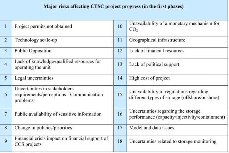
To analyze the reasons why a CTSC project might not be progressed, the risks related to the very first phases of the project are extracted from the overall list. The result is a list of eighteen major risks (Table 1.5).
Table 1.5: Major risks affecting the very first phases of the project
Major risks affecting CTSC project progress (in the first phases)
1 Project permits not obtained 10 Unavailability of a monetary mechanism for CO2
2 Technology scale-up 11 Geographical infrastructure
3 Public Opposition 12 Lack of financial resources
4 Lack of knowledge/qualified resources for
operating the unit 13 Lack of political support
5 Legal uncertainties 14 High cost of project
6
Uncertainties in stakeholders
requirements/perceptions - Communication problems
15 Unavailability of regulations regarding different types of storage (offshore/onshore)
7 Public availability of sensitive information 16 Uncertainties regarding the storage
performance (capacity/injectivity/containment)
8 Change in policies/priorities 17 Model and data issues
9 Financial crisis impact on financial support of
CCS projects 18 Uncertainties related to storage monitoring
In Chapter 3, we will readdress these major risks and review the risks that could be analyzed with our systemic approach, explained subsequently.
![Figure 1.1: Key technologies for reducing CO 2 emissions under the BLUE Map scenario [IEA, 2010]](https://thumb-eu.123doks.com/thumbv2/123doknet/3009140.84477/24.892.159.810.206.473/figure-key-technologies-reducing-emissions-blue-map-scenario.webp)
![Figure 1.6: CO 2 recovery by chemical absorption, Typical Process Flow Diagram [IPCC 2005]](https://thumb-eu.123doks.com/thumbv2/123doknet/3009140.84477/31.892.163.821.125.555/figure-recovery-chemical-absorption-typical-process-flow-diagram.webp)
![Figure 1.10: Schematic risk profile for a storage project [GCCSI, 2011a]](https://thumb-eu.123doks.com/thumbv2/123doknet/3009140.84477/43.892.146.797.350.776/figure-schematic-risk-profile-for-storage-project-gccsi.webp)
![Figure 1.12: Components of Risk [Leveson, 1995]](https://thumb-eu.123doks.com/thumbv2/123doknet/3009140.84477/48.892.149.792.600.748/figure-components-of-risk-leveson.webp)
![Table 1.6: Available Risk Assessment methodologies for CO 2 storage [Condor et al., 2011]](https://thumb-eu.123doks.com/thumbv2/123doknet/3009140.84477/57.892.133.795.197.672/table-available-risk-assessment-methodologies-storage-condor-et.webp)