A finite element/quaternion/asymptotic numerical method for the 3D simulation of flexible cables
Texte intégral
Figure
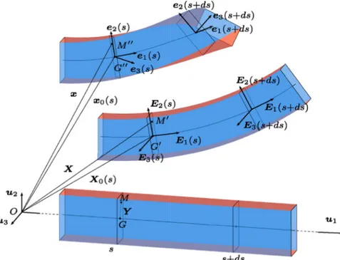


![Fig. 12. Deformed shape of the initially curved rod for the Lazarus et al. [21] experiment.](https://thumb-eu.123doks.com/thumbv2/123doknet/7426874.219480/15.892.482.809.705.1075/fig-deformed-shape-initially-curved-rod-lazarus-experiment.webp)
![Fig. 13. Equilibrium curve of straight (left) and curved (right) Lazarus et al. [21] rods.](https://thumb-eu.123doks.com/thumbv2/123doknet/7426874.219480/16.892.169.728.82.309/fig-equilibrium-curve-straight-left-curved-right-lazarus.webp)
Documents relatifs
5 shows the mechanical deformations of the actuation unit when a dc voltage is applied. One point of investigation was the nonlinear dynamic response of the micropump. The pump
(Note that the factors N 1 in the numerator and the denominator finally cancel out!). This means that to calculate the nodal strains, one need not in fact worry about the subdomains Ω
In this paper, we presented the numerical analysis of a finite element scheme for the optimal control of bidomain-bath model in cardiac electrophysiology. In this regard, first
ذﺎﺘﺳﻷا : ارﺮﻘﻣ اﻮﻀﻋ ﻲﻠﮭﺳ روﺪھز. ذﺎﺘﺳﻷا : ﺎﺸﻗﺎﻨﻣ اﻮﻀﻋ ردﺎﻘﻟا ﺪﺒﻋ ﻒﻠﺨﯾ. ةذﺎﺘﺳﻷا : ﺎﺸﻗﺎﻨﻣ اﻮﻀﻋ ﺔﺤﯿﺘﻓ نﻮﻨﻋز.. ﺔﯿﻟﺎﻐﻟا ﻲﻣأ ﻰﻟإ. ﻢﮭﺋﺎﻨﺑأ و ﻲﺗاﻮﺧأ ﻞﻛ
In [2, 3] Borri and Bottasso thoroughly investigated the idea of replacing the stress-couple resultant m and the specific angular momentum π, which are defined with respect to the
Many factors, such as the initial concentration of carbon source, fermentation time, incubation temperature, inoculum size, shell size, volume and medium composition
Comparativement à d autres études, le maximum d activité amylasique est observé au cours de la phase d accélération de la croissance ; 78 heures pour la souche Lipomyces sp
Conception du réseau d’adaptation d’impédance Comme il a été mentionné dans le premier chapitre, le transfert maximal de la puissance RF vers le circuit de conversion
