is an open access repository that collects the work of Arts et Métiers Institute of
Technology researchers and makes it freely available over the web where possible.
This is an author-deposited version published in:
https://sam.ensam.eu
Handle ID: .
http://hdl.handle.net/10985/19160
To cite this version :
Matthieu BONNERIC, Charles BRUGGER, Nicolas SAINTIER - Effect of hot isostatic pressing on
the critical defect size distribution in AlSi7Mg0.6 alloy obtained by selective laser melting
-International Journal of Fatigue - Vol. 140, p.105797 - 2020
Contents lists available atScienceDirect
International Journal of Fatigue
journal homepage:www.elsevier.com/locate/ijfatigue
Effect of hot isostatic pressing on the critical defect size distribution in
AlSi7Mg0.6 alloy obtained by selective laser melting
Matthieu Bonneric
a,b,⁎, Charles Brugger
a, Nicolas Saintier
aaArts et Metiers Institute of Technology, University of Bordeaux, CNRS, Bordeaux INP, INRAE, HESAM Université, I2M Bordeaux, F-33400 Talence, France bIRT Saint Exupery, B612 - 3 rue Tarfaya- CS 34436, 31405 Toulouse cedex, France
A R T I C L E I N F O Keywords: Additive manufacturing Al-Si alloys Defects Fatigue A B S T R A C T
This study focuses on the influence of defect density on the sizes of the critical defects responsible for fatigue failure in AlSi7Mg0.6 alloy produced by Selective Laser Melting. Samples having similar microstructures and different defect densities were obtained combining Hot Isostatic Pressing and T6 treatments. Defect populations were analyzed using X-ray tomography, and fatigue tests were performed to determine the critical defect dis-tributions. A method allowing for the prediction of these distributions from the CT scan data was then proposed, and discussed with regard to the actual distributions obtained from the fatigue tests.
1. Introduction
Over the past ten years, there was an ongoing effort to improve the quality of the parts produced by Selective Laser Melting (SLM), in particular for the Al-Si alloys[1–3]. However, in these materials the fatigue damage remains driven by defects [4–6], whose generation during the manufacturing process cannot be fully avoided despite the serious improvements in the laser powder-bed fusion technologies. In Al-Si alloys, these process induced defects usually correspond to lack-of-fusion defects, which have tortuous shapes and result from un-melted areas, and to gas pores resulting from the entrapment of gas bubbles [7,8].
The influence of defects on the fatigue behavior is a well-known issue on which there is a substantial literature. In particular, it is well established that the defect size is one of the key parameters governing the fatigue strength of metals[9,10]. Several studies demonstrated that the fatigue strength of defective materials can be properly depicted using the Kitagawa–Takahashi diagram[11–13], which describes the evolution of the fatigue strength as a function of the sizes of the defects that were responsible for fatigue failure. These approaches are based on fracture mechanics, and consider the defects as cracks that are likely to propagate under a cyclic loading[14,15].
As the prediction of the fatigue strength requires the value of the critical defect size, several methods were proposed to assess the prob-ability related to the size of the largest defect contained in the volume V of any loaded part. These methods are usually based on the statistical
analyses of the defect size distributions obtained from metallography or X-ray tomography analyses. A common procedure consists in the ob-servation of N distinct metallographic cross-sections having the same areaS0, and the measurement of the size of the largest defect found in each section. The different measurements are then used to build and identify a Large Extreme Value Distribution (LEVD) associated to the defect size[16,17]. This statistical law, which is associated to the in-spected sectionS0, can then be manipulated to predict the LEVD asso-ciated to the volume V of the loaded part by accounting for volume effects[18]. More recently, a similar concept of extreme value statistics was applied on CT scan observations to assess the probability related to the size of the largest defect contained in the volume V of AlSi10Mg parts produced by SLM[19].
However, the size is not the only parameter to consider in the identification of the critical defects. The position of the defect with respect to the surface of the loaded part is also an important issue[10], and the critical fatigue cracks usually initiate at surface or subsurface defects in the High Cycle Fatigue (HCF) regime, even in the presence of larger internal defects [20–22]. This predominance of failures origi-nating from surface or subsurface defects was also observed for the Al-Si alloys produced by SLM[23,4]. This latter phenomenon can be ac-counted for in the prediction of the size distribution of the critical de-fects by restricting the aforementioned volume V to a sub-volume cor-responding to the subsurface portion of the loaded part. The application of such a procedure, which assumes that the critical defect is the largest defect found in the subsurface portion of the part, has provided
https://doi.org/10.1016/j.ijfatigue.2020.105797
Received 24 February 2020; Received in revised form 19 June 2020; Accepted 20 June 2020
⁎Corresponding author at: Arts et Metiers Institute of Technology, University of Bordeaux, CNRS, Bordeaux INP, INRAE, HESAM Université, I2M Bordeaux, F-33400 Talence, France.
E-mail address:matthieu.bonneric@ensam.eu(M. Bonneric).
International Journal of Fatigue 140 (2020) 105797
Available online 05 July 2020
0142-1123/ © 2020 Elsevier Ltd. All rights reserved.
satisfying results for the AlSi10Mg alloy produced by SLM[24]. Although the detrimental impact of the defects is frequently re-ported in the literature on the Al-Si alloys produced by SLM, the po-tential benefits of a Hot Isostatic Pressing (HIP) treatment was rarely studied. Some studies showed that the application of HIP without any subsequent heat-treatment lead to a significant decrease of the strength and fatigue resistance, even if the porosity is reduced[25,26]. In ad-dition, several studies showed that the fatigue performance and ducti-lity can be improved by the application of a T6 treatment, although these improved properties come at the expense of some tensile strength [27–29]. Recently, the combination of HIP with a subsequent T6 treatment was investigated for the AlSi10Mg alloy [30]. The authors found that this treatment produced a microstructure similar to the only T6 material, but was ineffective in eliminating all the defects.
This study aims to investigate the influence of the reduced defect density induced by HIP prior to a T6 treatment on the critical defect distribution for the case of the AlSi7Mg0.6 alloy, in order to better understand the fatigue properties resulting from this treatment with respect to an only T6 treatment. The defect populations were analyzed using X-ray tomography for both HIP + T6 and T6 materials. Uniaxial fatigue tests were conducted, and the SEM observations of the fracture surfaces allowed for the characterization of the critical defect dis-tributions. An approach was then proposed to predict these distribu-tions from the CT scan data, and discussed with regard to the actual distributions obtained from fracture surfaces.
2. Material and methods
Cylindrical samples were produced on a SLM 280HL powder bed machine on the additive manufacturing platform (FUTURPROD) of I2M institute, using the AlSi7Mg0.6 aluminium alloy. The process para-meters recommended by the manufacturer for Al-Si alloys were used (seeTable 1), and the powders were dried under inert environment at 150°C for 12 h prior to the manufacturing. All samples were built in the vertical direction. A first batch of samples was then subjected to a T6 heat-treatment, consisting in a solution treatment at 535°C for 2 h, followed by a water quenching and an artificial aging at 170 °C for 4 h. These samples will be referred as T6 samples in what follows. A second batch of samples was subjected to a HIP treatment consisting in 2 h at 500 °C under 100 MPa, and then to the T6 treatment described above. These samples will be referred as HIP + T6 samples in what follows. Fatigue specimens, whose dimensions are provided in Fig. 1, were machined from these two batches after heat-treatments. The machined surface finish was meant to prevent from the influence of the surface roughness on the fatigue behavior, as this work focuses on the influence of defects.
Fig. 2provides observations of the microstructures related to the two heat-treatments considered in this study. These observations showed no significant difference between the two microstructures at a microscopic scale. Both T6 and HIP + T6 lead to the complete elim-ination of the initial dendritic structure, with the development of Si precipitates at grain boundaries. In addition, the average grain sizes were measured from the transverse sections see (Fig. 2a and c) and were found to be 10 μm for both T6 and HIP + T6.
The defect populations in T6 and HIP + T6 specimens were char-acterized using X-ray tomography. For each batch, the gauge lengths of 6 fatigue specimens were fully imaged with a voxel size of 4.7 μm, corresponding to an inspected volume of 1710 mm3. The obtained data were analyzed using the AVIZO and ImageJ software. A median filter
was systematically applied in a first place to reduce the noise and ob-tain an almost uniform gray level in the melted regions. The use of a threshold on the gray levels then allows for the separation of the dif-ferent defects from the bulk material. It should be specified that only thresholded objects with at least 8 voxels were considered to be defects. Different features were evaluated for each defect (position, volume, sphericity, etc…). In particular, the distribution of the Murakami area parameter [31], which is commonly used to depict defect criticality with respect to fatigue, was assessed using a script with the ImageJ software. As the fatigue behavior is mostly driven by the large defect population, only the defects of size area >30 µm were selected to build defect size distributions. The choice of this threshold value will be justified in Section4.
Micro-hardness measurements (Vickers) were performed on mirror polished samples, applying a 100 g load with a 10 s indentation time. For each sample, 25 indentations were conducted on both transverse and longitudinal sections. In addition to T6 and HIP + T6 samples, an as-built (AB) sample was also tested to have reference values corre-sponding to the initial metallurgical state.
Tension/tension fatigue tests were conducted on a Zwick resonant machine at room temperature in air and at a frequency of 80 Hz. All specimens were tested applying aR=0.1 load ratio. The stop criterion was a frequency drop of 0.5 Hz corresponding to a crack of approxi-mately 1.5 mm in depth, or a maximum number of cycles of2×106 cycles. The staircase method was used to assess the fatigue resistance at
×
2 106cycles. Following this procedure, each specimen was tested at one stress level only. The step between two levels was 20 MPa for the T6 material and 10 MPa for the HIP + T6 material. Please note that the non-broken specimens were also subjected to a Locati procedure by steps of 10 MPa until failure was detected, in order to observe the critical defect through SEM observations. However the results from these Locati procedures were not reported in the S-N curve presented in Section3.3.
3. Results
3.1. Defect characterization
The total number of defects found in the whole volume inspected with X-ray tomography was 244000 for T6 specimens, and 41000 for HIP + T6 specimens. Thus, the HIP treatment has a non negligible impact on the defect density, although it does not allow for the com-plete elimination of the defects, most likely due to the presence of gas trapped in the defects. Fig. 3 shows the evolution of the sizeV1/3 evaluated with respect to the sphericity S for the defect populations related to the T6 and HIP + T6 specimens. When considering the large Table 1
Process parameters recommended for Al-Si alloys.
Layer thickness Laser power Scan velocity Hatchs pacing Scanning strategy Base plate heating Atmosphere
30 μm 350 W 1650 mm/s 130 μm Stripes 150 °C Argon
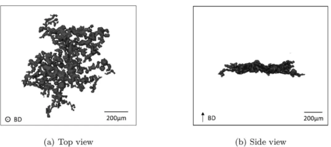
defects in T6 specimens, meaning those withV1/3>60 µm, the spheri-city ranges within 0.2 and 1.0 with a mean value of 0.68, which reflects the significant variability in the morphology of the defects generated by the SLM process. When considering the defects of sizeV1/3>60 µmin HIP + T6 specimens, the sphericity values fall within a narrower range with a mean value of 0.55. This general decrease in the sphericity was attributed to a flattening of the defects induced by the HIP treatment, which was observed on three-dimensional views of the defects analyzed
with X-ray tomography (Fig. 4). Indeed, the vizualisation of some particular defects in T6 specimens (Fig. 4a and b) and HIP + T6 spe-cimens (Fig. 4c and d) suggests that the defects tend to be flattened with respect to the building direction when a HIP treatment is applied prior to T6. This assumption was later confirmed by the observations of the fracture surfaces, where the critical defects in the HIP + T6 specimens were found less deep than the critical defects related to T6 specimens. Fig. 5b shows the cumulative distributions of the defect size area in T6 and HIP + T6 specimens. Only the defects of size area >30 µm were selected to build these distributions, which corresponded to 42000 defects in T6 specimens and 12000 defects in HIP + T6 specimens. Although the HIP treatment prior to T6 was responsible for a significant reduction of the number of defects, as illustrated by the defect count histogram shown inFig. 5a, the two distributions were found almost identical. This unique distribution can be fitted with a generalized Pareto distribution, for which the expression of the cumulative dis-tribution function is:
= − ⎛ ⎝ + − ⎞⎠ − F x γx u σ ( ) 1 1 γ 1 (1) whereγ=0.105,u=29.97 µm,σ=9.22 µm. 3.2. Hardness measurements
Fig. 6provides the results of the micro-hardness measurements. The hardness was approximately 120 HV in both transverse and long-itudinal directions for the as-built condition. After T6, the hardness is slightly decreased to 110 HV in the transverse direction and to 100 HV Fig. 2. Observations of the microstructures after a chemical etching using Keller’s reagent.
Fig. 3. Analysis of the defects observed with X-ray tomography: defect size V1/3 as a function of sphericity S.
M. Bonneric, et al. International Journal of Fatigue 140 (2020) 105797
in the longitudinal direction. The inability of the T6 treatment to en-hance the hardness of Al-Si alloys produced by SLM was already re-ported in the literature [32,30], and one might assume that the de-velopment of precipitates during the treatment does not overcome the loss of the fine Si network, which is most likely the main contributor to the strengthening of the as-built material. When HIP is applied prior to T6, the hardness is 120 HV in both transverse and longitudinal direc-tions, as for the as-built condition. Thus, the application of the HIP prior to T6 results in a hardness that is slightly higher compared to the T6 condition. Since the HIP treatment consists in both heating 2 h at 500 °C and applying 100 MPa, the increase in the Vickers hardness could possibly be attributed either to a better dissolution of the alloying elements leading to a better precipitation hardening, or to a density increase. A work is in progress to evaluate the effect of the sole thermal part of the treatment, but it is not possible yet to differentiate thermal and mechanical effects.
3.3. Fatigue tests
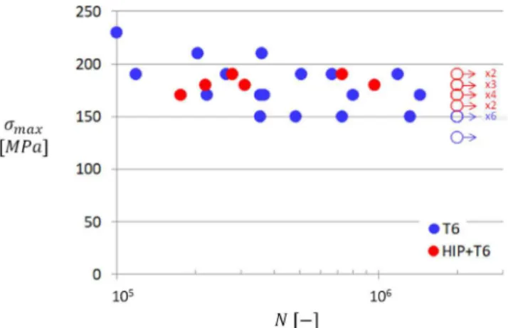
Fig. 7shows the S-N curves obtained with aR=0.1 load ratio for T6 and HIP + T6 specimens. The fatigue resistances at2×106cyclesσ
max d, evaluated with the staircase method was152 MPa±8 MPa for T6 spe-cimens, and 177 MPa±10 MPa for HIP + T6 specimens. Thus, the
application of the HIP treatment prior to T6 allowed for a slight in-crease (16%) in the fatigue resistance, although no significant differ-ence was observed between the two batches in terms of fatigue lives shown inFig. 7.
For T6 specimens, SEM observations of the fracture surfaces in-dicated that the fatigue cracks systematically initiated at defects. These critical defects mostly corresponded to lack-of-fusion defects (Fig. 8)a and gas pores (Fig. 8b), which are usually observed in the Al-Si alloys produced by SLM. In some rare cases (3 cases among the 22 specimens Fig. 4. Three dimensional views of particular defects observed with X-ray tomography. The building direction is indicated (BD).
Fig. 5. Defect size distributions corresponding to the observations of T6 samples and HIP + T6 samples with X-ray tomography.
Fig. 6. Comparison of the micro-hardness measurements between as-built samples (AB), T6 samples and HIP + T6 samples.
observed), clusters of small gas pores were also found responsible for fatigue failure (Fig. 8c). This particular kind of defect could also be observed in the T6 specimens characterized with X-ray tomography, and the observations indicated that the clusters were contained within a few layer thicknesses, as illustrated inFig. 9. One might assume that
these defects resulted from a local poor powder spreading, although their precise origin is difficult to determine. Besides, it is interesting to note that such clusters were never observed in the HIP + T6 specimens. However, as they were rare, and due to the inability of properly mea-suring their sizes from the observations of the fracture surfaces, the clusters were not accounted for in any of the analyzes presented in this study. The sizes area of the other critical defects were evaluated using the measurements of the defect areas on the fracture surfaces, as illu-strated inFigs. 8a and b. Please note that, for the sake of consistency with X-ray tomography data, the effective defect size – as defined in [33]for instance – was not considered in the present study. The sizes of the critical defects ranged from 20 μm to 117 μm for the T6 specimens, and no distinction could be made between the lack-of-fusion defects and the gas pores regarding their sizes. In addition, it appeared that all these defects were close to the surface of the specimens, and the dis-tance d between the surface and the center of the defect did not exceed 85 μm. However, no correlation was found between the sizes of the defects and the thicknesses of the bridge of material between the defect and the specimen surface. It should be noted that all defect measure-ments are provided inTables 2 and 3at the end of the document.
SEM observations of the fracture surfaces indicated that the fatigue cracks also initiated at surface or subsurface defects for the HIP + T6 specimens, as illustrated in Fig. 10. The sizes of the critical defects ranged from 37 μm to 125 μm, and the distance between the surface Fig. 7. S-N curves for a R = 0.1 load ratio for T6 specimens and HIP + T6
specimens.
Fig. 8. Examples of typical critical defects observed on the fracture surfaces of T6 specimens after fatigue testing.
M. Bonneric, et al. International Journal of Fatigue 140 (2020) 105797
and the center of the defect did not exceed 90 μm. One can note that these values are very similar to those related to the T6 specimens. In addition,Fig. 11shows the cumulative size distributions of the critical defects observed in the T6 and HIP + T6 specimens, where one can see that the two distributions are nearly identical. Thus, even if the appli-cation of the HIP treatment prior to T6 allowed for a significant de-crease of the defect density compared to the T6 material, it did not affect the distribution of the critical defects responsible for fatigue failure. One can also note that the defects inFig. 11might appear in small bundles of the same size, as for the defects of sizes 60 μm, 80 μm and 100 μm in the T6 material. Since none of the steps involved in the measurement of these values may introduce such a threshold effect, the latter one is probably related to the manufacturing process. However, this relation was not investigated in the present study.
4. Discussion
The previous results show that the application of a HIP treatment prior to T6 has a very limited impact on the fatigue behavior. Indeed, it was shown inFig. 7that the S-N curves of the T6 and HIP + T6 ma-terials overlap, and the examination of the fracture surfaces indicated that the fatigue cracks in the HIP + T6 material initiated on defects of sizes and positions similar to the T6 material. Yet, a slight increase in the fatigue strength assessed with the staircase method was observed. However, as opposed to other additively manufactured alloys for which the improvement of the fatigue properties mostly results from the elimination of the defects, it is believed that this slight increase is only the result of the slight increase in the material strength highlighted by
the micro-hardness measurements (Fig. 6). Indeed, according to the Murakami theory[10], the increase in the Vickers hardness between T6 and HIP + T6 materials produces a 9% increase in the fatigue strength, which is less but close to the 16% increase that was experimentally observed.
The fact that the cumulative size distributions of the critical defects observed in the T6 and HIP + T6 batches (Fig. 11) are nearly identical Fig. 9. Three dimensional views of a cluster of small gas pores in a T6 specimen observed with X-ray tomography.
Fig. 10. Examples of typical critical defects observed on the fracture surfaces of HIP + T6 specimens after fatigue testing.
Fig. 11. Cumulative size distributions of the critical defects constructed using the measurements from the fracture surfaces.
was somewhat unexpected, considering that the T6 and HIP + T6 materials display almost identical defect size distributions (Fig. 5) but quite different defect densities. Indeed, 12000 defects of size
>
area 30 µm were found in the whole volume inspected with X-ray tomography for the HIP + T6 specimens, which was1710 mm3. This corresponded to a defect density of7.02 mm−3. For the T6 specimens, 42000 defects of size area >30 µm were found, corresponding to a defect density of24.55 mm−3. One could expect this lower defect density for the HIP + T6 specimens to result in statistically smaller critical defects when a relatively small volume is considered, namely the sub-surface area of a fatigue specimen which is approximately 20 mm3. In order to better understand these experimental results, this section fo-cuses on the effect of defect density on the size distribution of the
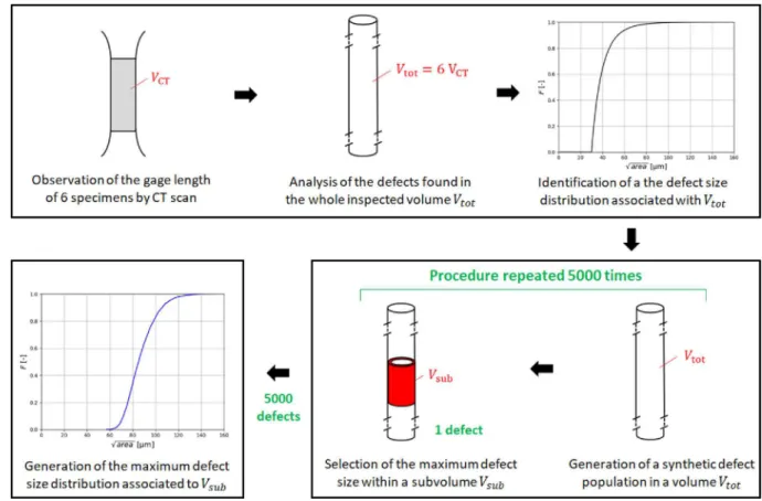
critical defects, assuming that the critical defect in a fatigue specimen is the largest defect in the subsurface area.Fig. 12describes the approach used to predict the distribution of the maximum defect size in the subsurface area of a fatigue specimen using the X-ray tomography ob-servations presented in Section3.1.
First, as described in Section2, the gauge lengths of fatigue speci-mens, each of them having a volumeVCT, were fully imaged using X-ray
tomography. For each batch, 6 specimens were observed, leading to a total inspected volumeVtot= 6VCT. This data allowed to plot the
cu-mulative defect size distributions (Fig. 5), and to identify the coeffi-cients of Eq.(1), both associated with the volumeVtot. Second, a script
was implemented to generate uniformly distributed defects in a similar
Vtot volume, with no intersection with the volume surface. The size
distribution followed Eq.(1). The number of defects in the volume is the number of defects experimentally observed inFig. 5(12000 for the HIP + T6 specimens, 42000 for the T6 specimens). A sub-volume Vsub
corresponding to the subsurface area of a fatigue specimen is then de-fined. This sub-volume corresponds to the area where fatigue cracks may initiate. Its depth has therefore been set to 85 μm, which is the maximal distance between the specimen surface and the center of the critical defect observed on the fracture surfaces. The largest defect size in this sub-volume is finally selected and retained. This defect genera-tion and sub-volume selecgenera-tion procedure is repeated 5000 times to generate a maximum defect size distribution associated with Vsub.
Fig. 13shows (dotted lines) the distributions obtained following this approach. As expected, the lower defect density for the HIP + T6 material compared to the only T6 actually results in a shift of the maximum defect size distribution. One should note that, among the 5000 defects selected through the procedure, none had a size
<
area 40 µm. This means that the predicted distributions do not depend on the choice made for the threshold value in Section2, where only defects with a size area >30 µm were retained to build defect size distributions from CT scan data. In other words, as the size of the largest defect in Vsubsystematically exceeds 40 μm, there is no need to Fig. 12. Description of the approach employed to predict the distribution of the maximum defect size in the subsurface area of a fatigue specimen.
Fig. 13. Prediction of the distribution of the maximum defect size in the sub-surface area of a fatigue specimen for T6 specimens and HIP + T6 specimens.
M. Bonneric, et al. International Journal of Fatigue 140 (2020) 105797
consider the defects smaller than the 30 μm threshold value to predict the size distribution of the largest defect in Vsubin the present study.
Another way to demonstrate that this threshold value has no influence is to count the number of defects in Vsub. About 160 defects were present
in each sub-volume for the HIP + T6 material, and 540 for the T6 material. This means that the threshold value is certainly low enough to ensure there is at least one defect in Vsubfor each draw. As explained
earlier, the depth of the sub-volume Vsubhas been initially set to 85 μm,
which is the maximal observed depth of a critical defect. In order to evaluate the sensitivity to this depth, the procedure was also applied for 50 μm and 120 μm values. The obtained distributions are depicted in Fig. 14. The medians of the distributions predicted for 50 μm, 85 μm and 120 μm depth values were equal to 67 μm, 86 μm and 97 μm for the HIP + T6 material, and 75 μm, 100 μm and 113 μm for the T6 material, respectively. For both materials, as expected, increasing the sub-volume Vsub induces a larger amount of defects in the sub-volume, and then
larger maximum defect sizes. Moreover, whatever the depth value, the lower defect density associated with the HIP treatment always results in a shift of the maximum defect size distribution. Regarding the median of the distribution, this shift is not much sensitive to the depth value and is about 15%. In what follows, the depth value was kept to 85 μm. Fig. 15compares the experimental distributions from the fracture surfaces, for which no significant difference was observed between the HIP + T6 and T6 (Fig. 11), and the predicted distributions, for which a lower defect density reduces the sizes of the larger defects found in Vsub
at each draw (Fig. 13). Since not many experimental data were
available, a Gumbel distribution describing the cumulative size dis-tribution of the critical defects was estimated for each material, and the associated 95% confidence intervals were calculated by bootstrapping and depicted onFigs. 15 and 16. Predictions are overall similar to the SEM observations. However, one can note that they are more accurate for the HIP + T6 material (Fig. 15b) than for the T6 material (Fig. 15a). Indeed, for the T6 specimens, the difference between experimental and predicted data is noticeable: critical defects on which fatigue cracks actually initiated are smaller than larger defects found in Vsub. One
explanation could be that the number of critical defects experimentally measured was not sufficient to build a representative size distribution. Another explanation could be that the larger defect found in Vsubis not
always the critical one, as fatigue damage may initiate on a smaller defect, either due to its position, morphology, or to the surrounding microstructure.
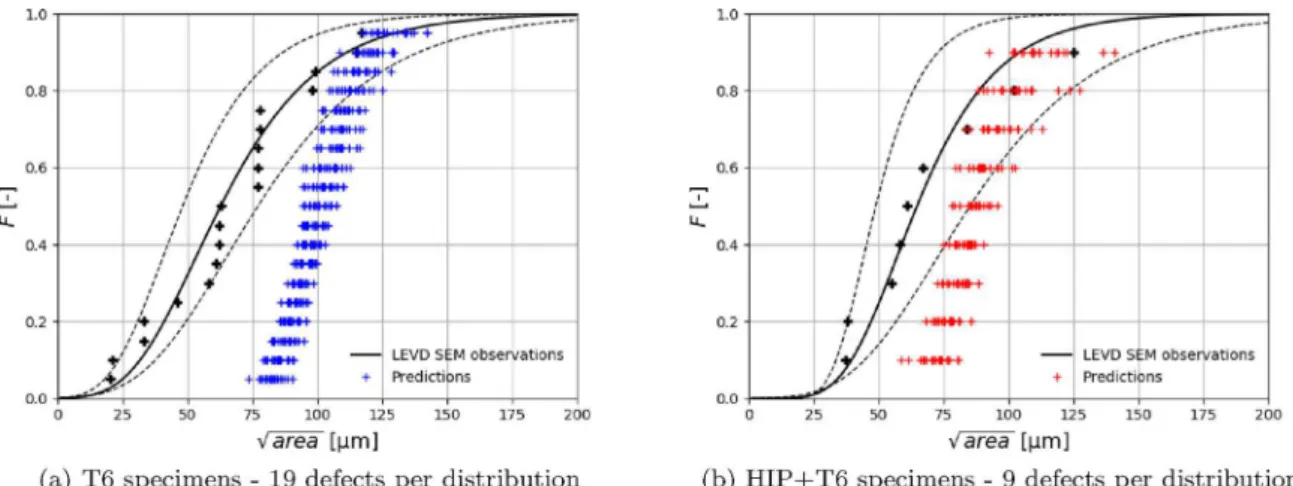
In order to assess the first assumption, 20 distributions were pre-dicted for each batch using a reduced number of defects corresponding to the number of critical defects observed on fracture surfaces (19 and 9 for the T6 and HIP + T6 batches, respectively). The objective here was to numerically assess how the size distribution may vary when only a few defects are used instead of 5000. The obtained results are provided in Fig. 16. When considering the distributions associated to the T6 material, it comes clear that the variability associated with a limited number of defects does not explain the difference between experimental and predicted results.
Thus, it is likely that this discrepancy results from the second Fig. 14. Influence of the the depth of the sub-volume Vsub, designated as e, on the predicted distribution.
Fig. 15. Comparison of the predicted distributions of the maximum defect size in the subsurface area of a fatigue specimen with the distributions constructed using the measurements of the actual critical defect sizes from the fracture surfaces.
assumption, meaning that the larger defect found in Vsubis not always
the critical one. This is consistent with the result onFig. 15b where the difference between the experimental and predicted distributions is much less pronounced for the HIP + T6 material, for which Vsub
con-tains less defects. Indeed, the probability to find a small defect in Vsub
whose criticality is greater than that of the largest defect, due to its local morphology or microstructure for instance, is lower when the defect density is reduced.
5. Conclusion
The results of this work can be summarized as follows:
1. A HIP process prior to a T6 treatment has no significant impact on the fatigue behavior compared to a T6 treatment, as the fatigue cracks in the HIP + T6 material still initiate on defects whose sizes and positions are similar to the T6 material. Only a slight increase in the fatigue strength was observed (+16%), which was attributed to the slight increase in the material hardness.
2. The HIP process does not change the defect size distribution, but allows for a significant decrease in the defect density.
3. Simulations of the critical defect size distribution showed that an increase in the defect density induces larger critical defects. However, these calculations rely on the assumption by which the critical defect is the largest one within the subsurface area of the loaded part, and the comparison with the experimental results suggests that this assumption becomes inaccurate for high defect densities, as for the T6 material.
Declaration of Competing Interest None.
Acknowledgments
This work falls within the framework of the Andduro project hosted by the French Institute of Technology IRT Saint Exupery, supported by Occitanie Region and industrial partners. In addition, the specimens were produced on the FUTURPROD additive manufacturing platform of I2M institute.
Fig. 16. Predicted distributions of the maximum defect size in the subsurface area of a fatigue specimen constructed with a reduced number of defects. Comparison with the distributions constructed using the measurements of the actual critical defect sizes from the fracture surfaces.
Table 2
Measurements of critical defect features from the fracture surface - T6 material.
Size area (μm) Distance from the center to the
surface (μm)
Smallest distance to the surface (μm) 62 48 0 99 55 8 21 21 10 33 27 0 63 49 18 78 37 0 61 50 0 33 26 6 115 84 16 78 71 0 77 68 20 98 79 18 77 56 29 58 32 8 77 53 0 46 21 0 117 79 13 62 42 14 20 21 9
M. Bonneric, et al. International Journal of Fatigue 140 (2020) 105797
Appendix A
References
[1] Olakanmi E, Cochrane R, Dalgarno K. A review on selective laser sintering/melting (SLS/SLM) of aluminium alloy powders: processing, microstructure, and properties. Prog Mater Sci 2015;74:401–77.https://doi.org/10.1016/j.pmatsci.2015.03.002. [2] Rao H, Giet S, Yang K, Wu X, Davies C. The influence of processing parameters on
aluminium alloy A357 manufactured by Selective Laser Melting. Mater Des 2016;109:334–46.https://doi.org/10.1016/j.matdes.2016.07.009.
[3] Aboulkhair N, Maskery I, Tuck C, Ashcroft I, Everitt N. Improving the fatigue be-haviour of a selectively laser melted aluminium alloy: Influence of heat treatment and surface quality. Mater Des 2016;104:174–82.https://doi.org/10.1016/j. matdes.2016.05.041.
[4] Romano S, Brückner-Foit A, Brandão A, Gumpinger J, Ghidini T, Beretta S. Fatigue properties of AlSi10mg obtained by additive manufacturing: Defect-based model-ling and prediction of fatigue strength. Eng Fract Mech 2018;187:165–89.https:// doi.org/10.1016/j.engfracmech.2017.11.002.
[5] Siddique S, Imran M, Walther F. Very high cycle fatigue and fatigue crack propa-gation behavior of selective laser melted AlSi12 alloy. Int J Fatigue
2017;94:246–54.https://doi.org/10.1016/j.ijfatigue.2016.06.003.
[6] Yang K, Rometsch P, Jarvis T, Rao J, Cao S, Davies C, et al. Porosity formation mechanisms and fatigue response in Al-Si-Mg alloys made by selective laser melting. Mater Sci Eng: A 2018;712:166–74.https://doi.org/10.1016/j.msea.2017.11.078. [7] Siddique S, Imran M, Wycisk E, Emmelmann C, Walther F. Influence of
process-induced microstructure and imperfections on mechanical properties of AlSi12 processed by selective laser melting. J Mater Process Technol 2015;221:205–13. https://doi.org/10.1016/j.jmatprotec.2015.02.023.
[8] Galy C, Le Guen E, Lacoste E, Arvieu C. Main defects observed in aluminum alloy parts produced by SLM: From causes to consequences. Addit Manuf
2018;22:165–75.https://doi.org/10.1016/j.addma.2018.05.005.
[9] Murakami Y, Endo T. Effects of small defects on fatigue strength of metals. Int J Fatigue 1980;2(1):23–30.https://doi.org/10.1016/0142-1123(80)90024-9. [10] Murakami Y. Metal fatigue: effects of small defects and nonmetallic inclusions.
Elsevier Edition; 2002.
[11] Vincent M, Nadot Y, Nadot-Martin C, Dragon A. Interaction between a surface defect and grain size under high cycle fatigue loading: Experimental approach for Armco iron. Int J Fatigue 2016;87:81–90.https://doi.org/10.1016/j.ijfatigue.2016. 01.013.
[12] Le V, Morel F, Bellett D, Saintier N, Osmond P. Simulation of the Kitagawa-Takahashi diagram using a probabilistic approach for cast Al-Si alloys under dif-ferent multiaxial loads. Int J Fatigue 2016;93:109–21.https://doi.org/10.1016/j. ijfatigue.2016.08.014.
[13] Beretta S, Romano S. A comparison of fatigue strength sensitivity to defects for materials manufactured by AM or traditional processes. Int J Fatigue 2017;94:178–91.https://doi.org/10.1016/j.ijfatigue.2016.06.020. [14] Kitagawa T. Applicability of fracture mechanics to very small cracks, ASM.
Proceedings of 2nd international conference on mechanical Metalspark. 1976. p. 627–31.
[15] El Haddad M, Topper T, Smith K. Prediction of non propagating cracks. Eng Fract Mech 1979;11(3):573–84.https://doi.org/10.1016/0013-7944(79)90081-X. [16] Murakami Y. Inclusion rating by statistics of extreme values and its application to
fatigue strength prediction and quality control of materials. J Res Nat Inst Stand Technol 1994;99(4):345–51.https://doi.org/10.6028/jres.099.032.
[17] Le V, Morel F, Bellett D, Saintier N, Osmond P. Multiaxial high cycle fatigue damage mechanisms associated with the different microstructural heterogeneities of cast aluminium alloys. Mater Sci Eng: A 2016;649:426–40.https://doi.org/10.1016/j.
msea.2015.10.026.
[18] Makkonen L, Rabb R, Tikanmäki M. Size effect in fatigue based on the extreme value distribution of defects. Mater Sci Eng: A 2014;594:68–71.https://doi.org/10. 1016/j.msea.2013.11.045.
[19] Romano S, Brandão A, Gumpinger J, Gschweitl M, Beretta S. Qualification of AM parts: Extreme value statistics applied to tomographic measurements. Mater Des 2017;131:32–48.https://doi.org/10.1016/j.matdes.2017.05.091.
[20] Andreau O, Pessard E, Koutiri I, Penot J, Dupuy C, Saintier N, et al. A competition between the contour and hatching zones on the high cycle fatigue behaviour of a 316L stainless steel: Analyzed using X-ray computed tomography. Mater Sci Eng: A 2019;757:146–59.https://doi.org/10.1016/j.msea.2019.04.101.
[21] El Khoukhi D, Morel F, Saintier N, Bellett D, Osmond P, Le V, et al. Experimental investigation of the size effect in high cycle fatigue: Role of the defect population in cast aluminium alloys. Int J Fatigue 2019;129.https://doi.org/10.1016/j.ijfatigue. 2019.105222.
[22] Wilson P, Saintier N, Palin-Luc T, Bergamo S. Isothermal fatigue damage mechan-isms at ambient and elevated temperature of a cast Al-Si-Cu aluminium alloy. Int J Fatigue 2019;121:112–23.https://doi.org/10.1016/j.ijfatigue.2018.11.016. [23] Yadollahi A, Shamsaei N. Additive manufacturing of fatigue resistant materials:
Challenges and opportunities. Int J Fatigue 2017;98:14–31.https://doi.org/10. 1016/j.ijfatigue.2017.01.001.
[24] Romano S, Abel A, Gumpinger J, Brandão A, Beretta S. Quality control of AlSi10mg produced by SLM: Metallography versus CT scans for critical defect size assessment. Addit Manuf 2019;28:394–405.https://doi.org/10.1016/j.addma.2019.05.017. [25] Uzan N, Shneck R, Yeheskel O, Frage N. Fatigue of AlSi10Mg specimens fabricated
by additive manufacturing selective laser melting (AM-SLM). Mater Sci Eng: A 2017;704:229–37.https://doi.org/10.1016/j.msea.2017.08.027.
[26] Tradowsky U, White J, Ward R, Read N, Reimers W, Attallah M. Selective laser melting of AlSi10Mg: Influence of post-processing on the microstructural and ten-sile properties development. Mater Des 2016;105:212–22.https://doi.org/10. 1016/j.matdes.2016.05.066.
[27] Bagherifard S, Beretta N, Monti S, Riccio M, Bandini M, Guagliano M. On the fatigue strength enhancement of additive manufactured AlSi10Mg parts by mechanical and thermal post-processing. Mater Des 2018;145:28–41.https://doi.org/10.1016/j. matdes.2018.02.055.
[28] Domfang Ngnekou J, Nadot Y, Henaff G, Nicolai J, Ridosz L. Influence of defect size on the fatigue resistance of AlSi10mg alloy elaborated by selective laser melting (SLM). Proc Struct Integr 2017;7:75–83.https://doi.org/10.1016/j.prostr.2017.11. 063.
[29] Maskery I, Aboulkhair N, Tuck C, Wildman R, Ashcroft I, Everitt N, et al. Fatigue performance enhancement of selectively laser melted aluminium alloy by heat treatment. Solid Freeform Fabric Symp 2015:1017–25.
[30] Kan W, Nadot Y, Foley M, Ridosz L, Proust G, Cairney J. Factors that affect the properties of additively-manufactured AlSi10Mg: Porosity versus microstructure. Addit Manuf 2019;29. 100805.
[31] Murakami Y, Endo M. Quantitative evaluation of fatigue strength of metals con-taining various small defects or cracks. Eng Fract Mech 1983;17(1):1–15.https:// doi.org/10.1016/0013-7944(83)90018-8.
[32] Aboulkhair N, Tuck C, Ashcroft I, Maskery I, Everitt N. On the Precipitation Hardening of Selective Laser Melted AlSi10Mg. Metall Mater Trans A 2015;46(8):3337–41.
[33] Masuo H, Tanaka Y, Morokoshi S, Yagura H, Uchida T, Yamamoto Y, et al. Effects of defects, surface roughness and hip on fatigue strength of Ti-6Al-4V manufactured by additive manufacturing. Proc Struct Integr 2017;7:19–26.https://doi.org/10. 1016/j.prostr.2017.11.055.
Table 3
Measurements of critical defect features from the fracture surface - HIP + T6 material.
Size area (μm) Distance from the center to the
surface (μm)
Smallest distance to the surface (μm) 102 92 0 67 44 0 58 26 0 55 26 0 61 44 12 38 29 14 84 68 16 125 76 0 37 38 14 10