48 WIND DIRECTIONS | March 2009 Wind power is one of the world’s fastest growing
energy sources. Wind turbines are large, fl exible structures which are subject to aerodynamic tran-sient excitation. These dynamic loads can result in signifi cant mechanical problems, sometimes with dramatic consequences, such as the failure of gear pinions, bearings and other components due to underestimated dynamic loading and related fatigue. There is clearly a need for simula-tion tools that can accurately model integral wind turbine behaviour. An innovative solution proce-dure is being developed in the framework of the
Towards reliable virtual
prototypes of wind turbines
Challenges in wind turbine design
One of the biggest challenges in wind turbine design concerns the turbine’s overall dynamic behaviour. Recently, the wind energy industry has often experienced problems with the power train and bearings after just a couple of years of successful operation, which is largely below the expected design life goal. All the forces and moments induced by the wind act on the turbine’s rotor shaft. Peak loads, sudden loading reversal, emergency stops, changing wind direction and vibrations all contribute to a highly dynamic effect. This is very far from a classic design approach, for which static conditions would be assumed. Evaluations of dynamic gearbox loads must therefore be carried out looking at the gearbox as part of a wind turbine – a complex system of fl exible components, joints and a control system. The whole mechatronical system - the mechanical system and its control devices – must be consid-ered when dynamic loads are estimated. There is therefore a need for dynamic models of the whole wind turbine, even when only a part of its design is being considered.
Over the past 20 years, the size of the wind turbine rotor has increased signifi cantly because it is linked to the amount of power generated. It is believed that this tendency will continue in the fu-ture. Flexibility and non-linear effects will become more and more predominant in the analysis as models become more realistic.
The UpWind European project
UpWind [1] is a European project funded by the EU’s Sixth Framework Programme. It started in March 2006 and runs until 2011. The goal of UpWind is to develop tools and component con-cepts for the large wind turbines of the future. The project covers all the fi elds involved in the design of a wind turbine, such as metrology for measuring fl uctuating wind speed, innovative blade design and manufacturing, power electronics for the drive train, rotor blades and rotor control, costs | science corner |
European project UpWind [1] to allow the dynam-ics of wind turbines to be accurately modelled. Based on SAMCEF Mecano [2], a general fi nite element approach applicable to fl exible multi-body systems, the procedure is being used at an industrial level [3,4] and has already proven to be effi cient for global and local (detailed) analyses.
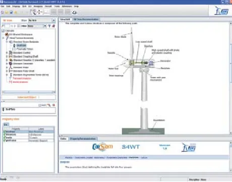
Figure 1. The compo-nents of a wind turbine and the model in the S4WT environment
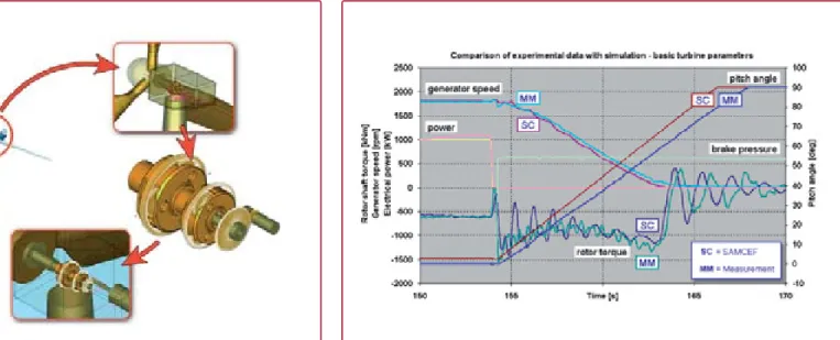
Figure 2. Some details of a model including rigid and Super Elements, and the gearbox model
In the Wind Directions Science Corner
you will fi nd an in-depth article on one
of the more technical aspects of the
wind industry
By Jan Hemmelmann, Andreas Heege, Didier Granville, Michaël Bruyneel
49 WIND DIRECTIONS | March 2009
analyses, aerodynamics, electric grid connection issues and integral design approach methodolo-gies. This last point is discussed below.
Global dynamic models
Wind turbine models turbines are developed with the SAMCEF fi nite element code [2,3] and run in an unique dedicated environment called S4WT – SAMCEF for Wind Turbines (see Figure 1). Several elements must be present to produce a realistic and reliable model for the computation of wind turbine drive train loads. Those loads can be associated with excitation induced by aero-dynamic rotor blade loads and electromagnetic generator torque. Moreover, the proper dynam-ics of the entire system, including all control mechanisms, must be considered as well. For the building of a virtual prototype of a wind turbine, an aerodynamic-mechanical approach is recom-mended. The mathematical approach in S4WT is based on a non-linear Finite Element formalism, which accounts for fl exible Multi-Body-System functionalities, control devices and aerodynamics in terms of the Blade Element Momentum Theory, simultaneously.
Besides structural and mechanical fi nite ele-ments, some specifi c elements such as fl exible bearings are used, which allow the production of light but very accurate models of complex gear-boxes included in the global wind turbine virtual prototype. Important characteristics such as fl ex-ibility and clearance can also be modelled (Figure 2). More details – and equations – can be found in Hegge, Betran and Radovcic’s recent report (see [3], below).
| science corner |
Results from the industry
Recent validations of numerical results against experimental measurements concerning an E-stop (emergency stop) simulation previously presented in [4] are briefl y reported here. E-stop simulations generate large dynamic oscillations. These oscilla-tions frequently produce backlashes. The results reported in Figure 3 present the variation of the rotor shaft torque, the variation of the blade pitch angles, the speed of high speed shaft, the disk brake pressure and fi nally variation of electric power over time, in a transient analysis conducted with SAMCEF and compared to experiments. As shown in the fi gure, at 154 seconds the electri-cal power drops, and 0.4 seconds later the full pressure of the disk brake is applied. In order to invert the rotor torque, the blade is pitched into a 90 degree position, out of the rotor plane and into the wind. At 163.5 seconds the generator rotation is fully stopped and from there the rotor oscillates and damps around the standstill position. The small time delays which are visible when the rotor torque crosses the zero torque line indicate the gearbox backlash.
From Figures 3 and 4, it appears that wind turbine models could be tuned so that the dif-ferences between the numerical results and the available data are generally less than 20%.
Figure 3: Emergency stop simulation: comparison of experimental data and S4WT results. Presented data: pitch angle, generator speed, brake pressure, power.
References
[1] UpWind European Project – http://www.upwind.eu [2] SAMCEF. http://www.samcef.com
[3] Heege A., Betran J. and Radovcic Y. (2007). “Fatigue load computation of wind turbine gearboxes by coupled fi nite element, multi-body system and aerodynamic analysis”, Wind Energy, 10 (5), pp. 395-413.
[4] Hemmelmann J. (2008). “Transmission & conversion – Workpackage activities and fi rst fi ndings”, EWEC 2008 Session BW2 “UPWIND”, 1st April 2008.