HAL Id: tel-02117812
https://pastel.archives-ouvertes.fr/tel-02117812
Submitted on 2 May 2019
HAL is a multi-disciplinary open access
archive for the deposit and dissemination of sci-entific research documents, whether they are pub-lished or not. The documents may come from teaching and research institutions in France or abroad, or from public or private research centers.
L’archive ouverte pluridisciplinaire HAL, est destinée au dépôt et à la diffusion de documents scientifiques de niveau recherche, publiés ou non, émanant des établissements d’enseignement et de recherche français ou étrangers, des laboratoires publics ou privés.
storage systems
Guillaume Ruty
To cite this version:
Guillaume Ruty. Towards more scalability and flexibility for distributed storage systems. Dis-tributed, Parallel, and Cluster Computing [cs.DC]. Université Paris-Saclay, 2019. English. �NNT : 2019SACLT006�. �tel-02117812�
NNT
:
2019SA
CL
distributed storage systems
Th `ese de doctorat de l’Universit ´e Paris-Saclay pr ´epar ´ee `a T ´el ´ecom ParisTech Ecole doctorale n◦580 Ecole Doctorale Sciences et Technologies de l’Information et de
la Communication (ED STIC)
Sp ´ecialit ´e de doctorat : Informatique
Th `ese pr ´esent ´ee et soutenue `a Paris, le 15 F ´evrier 2019, par
G
UILLAUMER
UTYComposition du Jury :
Andr ´e-Luc Beylot
Professeur, ENSEEIHT (IRIT) Rapporteur Stefano Secci
Professeur, CNAM Rapporteur
Raouf Boutaba
Professeur, University of Waterloo Examinateur Nadia Boukhatem
Professeur, Telecom ParisTech (LTCI) Pr ´esident Damien Saucez
Charg ´e de Recherche, INRIA Examinateur Jean-Louis Rougier
Professeur, Telecom ParisTech (LTCI) Directeur de th `ese Andr ´e Surcouf
Distinguished Engineer, Cisco Systems (PIRL) Co-encadrant de th `ese Mark Townsley
DOCTORAL
T
HESIS
Towards more scalability and
flexibility for distributed storage
systems
Author:
Guillaume Ruty
Supervisor:
Dr. Jean-Louis Rougier
A thesis submitted in fulfillment of the requirements
for the degree of Doctor of Philosophy
in the
Cisco Systems Paris Innovation and Research Lab (PIRL)
Laboratoire Traitement et Communication de l’Information
(LTCI)
Declaration of Authorship
I, Guillaume Ruty, declare that this thesis titled, “Towards more scalability and flexibility for distributed storage systems” and the work presented in it are my own. I confirm that:
• This work was done wholly or mainly while in candidature for a re-search degree at this University.
• Where any part of this thesis has previously been submitted for a de-gree or any other qualification at this University or any other institu-tion, this has been clearly stated.
• Where I have consulted the published work of others, this is always clearly attributed.
• Where I have quoted from the work of others, the source is always given. With the exception of such quotations, this thesis is entirely my own work.
• I have acknowledged all main sources of help.
• Where the thesis is based on work done by myself jointly with others, I have made clear exactly what was done by others and what I have contributed myself.
Signed:
“La maturité de l’homme est d’avoir retrouvé le sérieux qu’on avait au jeu quand on était enfant.”
TELECOM PARISTECH
Abstract
Laboratoire Traitement et Communication de l’Information (LTCI)
Doctor of Philosophy
Towards more scalability and flexibility for distributed storage systems
The exponentially growing demand for storage puts a huge stress on tra-ditionnal distributed storage systems. While storage devices’ performance keep improving over time, current ditributed storage systems struggle to keep up with the rate of data growth, especially with the rise of cloud and big data applications. Furthermore, the performance balance between stor-age, network and compute devices has shifted and the assumptions that are the foundation for most distributed storage systems are not true anymore.
This dissertation explains how several aspects of such storage systems can be modified and rethought to make a more efficient use of the resource at their disposal. It presents 6Stor, an original architecture that uses a dis-tributed layer of metadata to provide flexible and scalable object-level stor-age, then proposes a scheduling algorithm improving how a generic storage system handles concurrent requests. Finally, it describes how to improve legacy filesystem-level caching for erasure-code-based distributed storage systems, before presenting a few other contributions made in the context of short research projects.
Les besoins en terme de stockage, en augmentation exponentielle, sont difficilement satisfaits par les systèmes de stockage distribué traditionnels. Même si les performances des disques continuent à s’améliorer, les systèmes de stockage distribué actuels peinent à suivre le croissance du nombre de données requérant d’êtres stockées, notamment à cause de l’avènement des applications de big data. Par ailleurs, l’équilibre de performances entre dis-ques, cartes réseau et processeurs a changé et les suppositions sur lesquelles se basent la plupart des systèmes de stockage distribué actuels ne sont plus vraies.
Cette dissertation explique de quelle manière certains aspects de tels sys-tèmes de stockages peuvent être modifiés et repensés pour faire une utilisa-tion plus efficace des ressources qui les composent. Elle présente 6Stor, une architecture de stockage nouvelle qui se base sur une couche de métadon-nées distribuée afin de fournir du stockage d’objet de manière flexible tout en passant à l’échelle. Elle détaille ensuite un algorithme d’ordonnancement des requêtes permettant à un système de stockage générique de traiter les requêtes de clients en parallèle de manière plus équitable. Enfin, elle décrit comment améliorer le cache générique du système de fichier dans le con-texte de systèmes de stockage distribué basés sur des codes correcteurs avant de présenter des contributions effectuées dans le cadre de courts projets de recherche.
Acknowledgements
The work presented here could not have been done without the help and support of many people.
I would first and foremost like to thank my advisors, Jean-Louis Rougier and André Surcouf for their continuous support and insight as well as for their good company. They made these 3 years feel like 1 and really focused my attention on the relevant topics when I started to feel lost in the diversity of subjects at hand.
I would also like to thank Aloys Augustin and Victor Nguyen, who joined the 6Stor project as developpers under a Cisco tech fund. Aloys really fleshed out the crude code base that I wrote as a first prototype of 6Stor. We also had lengthy discussions about certain design or implementation details of 6Stor during which his insight helped me elaborate the global architecture. He also implemented RS3 – our storage scheduler – in 6Stor’s storage servers. Victor mainly worked on the 6Stor block device implementation and on the erasure-code based storage system replica cache.
This section could not go without a hearty mention to Cisco and to Mark Townsley, who founded and runs Cisco’s PIRL (Paris Innovation and Re-search Lab), and recruited me first as a reRe-search intern then as a PhD student, and without whom this work would simply not exist. He has consistently been a driving force behind 6Stor, from the project’s origins to the end of my PhD. The same mention goes to Jérome Tollet, who piqued my curiosity on numerous occasions and subjects during our car rides or coffee breaks, and participated to the elaboration of RS3 with Aloys and me, in addition of be-ing a merry desk neighbour.
My final thanks go to my fellow PhD students and friends, namely Jacques Samain, Yoann Desmouceaux, Marcel Enguehard, Mohammed Hawari and Hassen Siad. Whether we gathered around the lunch table, the coffee ma-chine or the babyfoot, they always kept the occasional dullness at bay and heavily contributed to making these 3 years truly special.
Contents
Declaration of Authorship i
Abstract iv
Acknowledgements v
1 What you should know about distributed storage systems 6
1.1 The different types of distributed storage system architectures 6
1.1.1 Network Attached Storage (NAS) and Storage Area
Net-work (SAN) . . . 7
1.1.2 Peer-to-Peer (P2P) networks . . . 7
1.1.3 Distributed Hash Tables (DHTs) . . . 9
1.1.4 Master-Slaves architectures . . . 13
1.1.5 Summarize . . . 16
1.2 Reliability in distributed storage systems . . . 16
1.2.1 Mirroring . . . 16
1.2.2 Replication . . . 17
1.2.3 Erasure Codes . . . 19
1.2.4 Erasure codes and replication: what is the trade-off . . 20
1.3 Consistency and consensus . . . 22
1.3.1 Theoretical frameworks . . . 22
Consistency and Availability: the CAP theorem . . . . 22
Database characteristics: ACID and BASE. . . 24
Client-centric and data-centric consistency models. . . 25
1.3.2 Consensus and consistency: how to reach it . . . 27
Consensus algorithms: Paxos and Raft. . . 27
Latency and Consistency, the (N,W,R) quorum model . 28 1.4 Examples of distributed storage systems . . . 31
2 6Stor 33 2.1 Why we built 6Stor from scratch . . . 34
2.1.1 Software layering . . . 34
2.1.2 Architectural reasons . . . 34
2.1.3 Ceph . . . 34
2.1.4 GFS . . . 36
2.1.5 Scaling the metadata layer and embracing the hetero-geneity . . . 37
2.2 6Stor architecture . . . 38
2.2.1 Architecture Description . . . 38
2.2.3 6Stor: An IPv6-centric architecture . . . 40
2.2.4 Description of basic operations . . . 42
2.2.5 Consistency . . . 45
2.3 Expanding or shrinking the cluster without impacting the clus-ter’s performance . . . 47
2.3.1 Storage Nodes. . . 47
2.3.2 Metadata Nodes . . . 48
2.3.3 Availability and data transfer . . . 48
2.4 Coping with failures: reliability and repair model . . . 50
2.4.1 Reliability . . . 50
2.4.2 Reacting to failures . . . 50
Short failure . . . 50
Definitive failure . . . 51
Voluntary shutdown and maintenance . . . 51
Maintaining reliability . . . 52
2.5 Considerations on the Architecture . . . 52
2.5.1 Client and Cluster Configuration . . . 52
2.5.2 Layer of Indirection . . . 52
2.5.3 Scalability . . . 53
2.5.4 Metrology and Analytics . . . 54
2.5.5 Limitations . . . 55
2.6 Experimental Evaluation . . . 55
2.6.1 Rationale . . . 55
2.6.2 Setup and Protocol . . . 55
2.6.3 Results . . . 57
2.6.4 Get Tests . . . 57
2.6.5 Post Tests . . . 59
2.6.6 CPU consumption analysis . . . 60
2.6.7 Performance impact of HTTP . . . 61
Protocol . . . 61
Results . . . 62
2.7 Conclusion . . . 62
3 6Stor extensions 65 3.1 Building a block device on 6Stor . . . 65
3.1.1 Different implementations. . . 65
3.1.2 A note on caching and consistency . . . 67
3.1.3 Performance benchmark . . . 68
3.2 Adapting 6LB to 6Stor . . . 71
3.2.1 Load balancing in distributed storage systems . . . 71
3.2.2 Segment-routing load-balancing . . . 73
3.2.3 Adapting 6LB to 6Stor . . . 74
3.2.4 Consequences on consistency . . . 75
4 Request Scheduler for Storage Systems (RS3) 78 4.1 Related work. . . 79 4.1.1 Packet scheduling . . . 80 4.1.2 I/O scheduling . . . 80 4.1.3 System-wide scheduling . . . 81 4.2 Designing RS3 . . . 81
4.2.1 Typical storage server implementation. . . 82
4.2.2 RS3’s rationales . . . 83
4.2.3 RS3’s batch budget allocation algorithm . . . 84
4.3 First evaluation and analysis. . . 86
4.3.1 Experimental protocol . . . 86
4.3.2 Throughput fairness results . . . 87
4.3.3 Response time results . . . 89
4.3.4 Throughput results . . . 89
4.4 Using Linux filesystem mechanisms to improve RS3 . . . 91
4.4.1 Sending hints to the kernel . . . 92
4.4.2 Response time and throughput results . . . 93
4.5 Going further with RS3 . . . 95
4.5.1 Evaluating batch budget’s impact on RS3’s performance. 95 4.5.2 Tweaking RS3 to enforce policies: Weighted-RS3 . . . . 97
4.5.3 Considerations on RS3 and its current implementation 98 4.6 Conclusion . . . 100
4.6.1 Going further . . . 100
5 Caching erasure-coded objects 102 5.1 Related Work . . . 104
5.2 Caching and Popularity In Distributed Storage Systems . . . . 106
5.2.1 System Architecture . . . 106 5.2.2 Object Caching . . . 107 5.3 Theoretical Evaluation . . . 109 5.3.1 Popularity Model . . . 109 5.3.2 System Model . . . 110 5.3.3 Performance Evaluation . . . 111
5.3.4 Results and evaluation . . . 113
5.4 Experimental Evaluation . . . 113
5.4.1 Experimental setup . . . 114
5.4.2 Results and Evaluation. . . 116
5.5 Conclusion . . . 117
A Predictive Container Image Prefetching 123 A.1 Motivations . . . 123
A.2 Storage and containers . . . 123
A.3 Some statistics about popular container images . . . 124
B Vectorizing TCP data handling for file servers 129
B.1 Motivations . . . 129
B.2 State of the art . . . 130
B.3 Segment-oriented TCP in VPP . . . 130
B.4 Zero-copy file server . . . 131
List of Figures
1 SSD and HDD cost evolution prediction . . . 2
2 Network, Storage and Memory hardware throughput evolution. 3 1.1 NAS and SAN . . . 8
1.1a NAS . . . 8
1.1b SAN . . . 8
1.2 Example of an unstructured P2P network with ad hoc connec-tions between nodes. . . 9
1.3 Example of a structured P2P network using a DHT to identify nodes.. . . 10 1.4 DHT illustration example . . . 11 1.5 DHT rebalancing . . . 14 1.5a DHT rebalancing . . . 14 1.5b DHT stable state . . . 14 1.6 GFS and HDFS SPOFs . . . 15 1.6a GFS Architecture . . . 15 1.6b HDFS Architecture . . . 15
1.7 Object-to-server mapping in Ceph . . . 18
1.8 Inter-object erasure code . . . 19
1.9 Intra-object erasure code . . . 20
1.10 Hybrid erasure code . . . 21
1.11 CAP theorem: case of a partition . . . 23
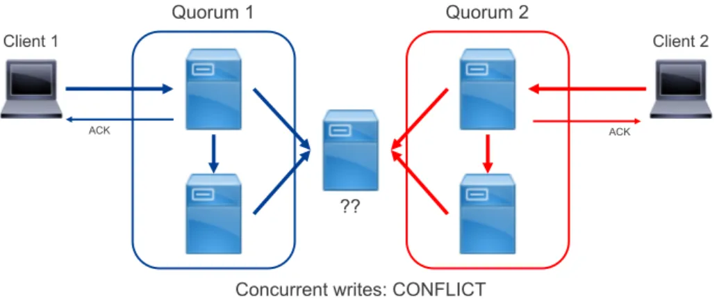
1.12 W > bN2cguarantees the impossibility of concurrent and dis-tinct writes to be simultaneously successfull. . . 30
1.12a Conflict example . . . 30
1.12b Conflict solved . . . 30
1.13 Write deadlock situation . . . 30
2.1 Example of a routable object replica IPv6 address decomposition. 38 2.2 Example of metadata load imbalance . . . 40
2.3 6Stor architecture example . . . 41
2.4 Object metadata example. . . 42
2.5 Sequence Diagrams of the 4 basic 6Stor operations.. . . 46
2.5a Post . . . 46
2.5b Get . . . 46
2.5c Rename . . . 46
2.5d Delete . . . 46
2.6 MG redistribution when including a new MN in the cluster. . 49
2.6a 32 MGs, 7 MNs . . . 49
2.6b 32 MGs, 8 MNs . . . 49
2.8 Test Results . . . 58
2.8a Gets. . . 58
2.8b Posts on SSD . . . 58
2.8c Posts on HDD . . . 58
2.9 Request per second per object size obtained with nginx and 6Stor 62 3.1 BUSE in Linux storage stack . . . 66
3.2 Illustration of the three 6Stor block device implementations when reading two files in parallel. . . 67
3.3 I/O per second benchmark results for 6Stor’s block device . . 69
3.3a I/O per second, 3 servers, read . . . 69
3.3b I/O per second, 3 servers, write . . . 69
3.3c I/O per second, 16 servers, read . . . 69
3.3d I/O per second, 16 servers, write . . . 69
3.4 Throughput benchmark results for 6Stor’s block device . . . . 70
3.4a Throughput, 3 servers, read . . . 70
3.4b Throughput, 3 servers, write . . . 70
3.4c Throughput, 16 servers, read . . . 70
3.4d Throughput, 16 servers, write . . . 70
3.5 6LB hunting example . . . 74
3.6 6StorLB: MN . . . 75
3.7 6StorLB: SN . . . 76
4.1 Budget allocation example . . . 85
4.1a First allocation phase . . . 85
4.1b Second allocation phase . . . 85
4.2 Average throughput per class . . . 88
4.3 Average throughput per batch budget . . . 88
4.4 Response time distribution of 4KB requests with and without RS3 . . . 90
4.4a Standard, read size = 4KB . . . 90
4.4b Standard, read size = 32KB . . . 90
4.4c Standard, read size = 64KB . . . 90
4.4d Standard, read size = 128KB . . . 90
4.4e RS3, batch budget = 32KB . . . 90
4.4f RS3, batch budget = 64KB . . . 90
4.4g RS3, batch budget = 128KB . . . 90
4.4h RS3, batch budget = 256KB . . . 90
4.5 Average throughput with and without RS3 . . . 91
4.6 Blocking time during object fetching with and without posix_fadvise 93 4.6a Without posix_fadvise . . . 93
4.6b With posix_fadvise . . . 93
4.7 Response time distribution of 4KB requests with and without RS3 . . . 94
4.7a Standard, read size = 4KB . . . 94
4.7b Standard, read size = 32KB . . . 94
4.7c Standard, read size = 64KB . . . 94
4.7e RS3, batch budget = 32KB . . . 94
4.7f RS3, batch budget = 64KB . . . 94
4.7g RS3, batch budget = 128KB . . . 94
4.7h RS3, batch budget = 256KB . . . 94
4.8 Average throughput with and without RS3 . . . 95
4.9 Cumulative distribution function of 4KB requests reponse time depending on the batch budget. . . 96
4.10 Total throughput and storage server CPU time for 40 concur-rent classes per batch budget. . . 97
5.1 Client requesting object B from a(2, r)erasure coded distributed object store (parity fragments not represented). . . 106
5.2 Fragments caching versus full replica caching. Caches repre-sented in dotted lines. . . 108
5.2a Legacy filesystem caching: client 2 gets E1 from cache but E2 from disk – the cache does not speed up object fetching. . . 108
5.2b Full replica caching: client 2 gets E from storage node 4’s cache directly. . . 108
5.3 Cache hit ratio . . . 112
5.3a Cache capacity: 0.01, Class repartition: [1, 1, 4, 4] . . . . 112
5.3b Cache capacity: 0.01, Class repartition: [1, 1, 1, 1] . . . . 112
5.3c Cache capacity: 0.05, Class repartition: [1, 1, 4, 4] . . . . 112
5.3d Cache capacity: 0.05, Class repartition: [1, 1, 1, 1] . . . . 112
5.3e Cache capacity: 0.1, Class repartition: [1, 1, 4, 4] . . . 112
5.3f Cache capacity: 0.1, Class repartition: [1, 1, 1, 1] . . . 112
5.4 Cache waste ratio . . . 114
5.4a Class repartition:[1, 1, 4, 4] . . . 114
5.4b Class repartition:[1, 1, 1, 1] . . . 114
5.5 Storage server implementation: a single generic fragment and object in memory, and enough generic fragments on disk to cycle through them without ever hitting the disk cache. . . . 115
5.6 Cache hit ratio for a real testbed . . . 117
5.7 Response time histograms . . . 118
5.7a Fragment cache, α=0.0 . . . 118
5.7b Replica cache, α=0.0 . . . 118
5.7c Fragment cache, α=0.4 . . . 118
5.7d Replica cache, α=0.4 . . . 118
5.7e Fragment cache, α=1.0 . . . 118
5.7f Replica cache, α=1.0 . . . 118
5.7g Fragment cache, α=1.6 . . . 118
5.7h Replica cache, α=1.6 . . . 118
A.1 Size and executable proportion distributions for 81 of the most popular docker images. . . 125
A.1a Container size distribution . . . 125
A.1b Distribution of the ratio of executables in container im-ages. . . 125
A.2 OPCISS Architecture. . . 126
A.3 Comparison of spin up strategies for containers. . . 128
A.3a Full download . . . 128
A.3b Slacker lazy fetching . . . 128
A.3c OPCISS predictive prefecthing . . . 128
B.1 VPP Architecture . . . 130
B.2 Application in VPP . . . 131
List of Tables
1 Estimation of data stored and processed daily by big tech com-panies. . . 3
1.1 Trade-off between degree and route length for DHTs. . . 11
1.2 Summarize of the different types of architectures and their char-acteristics . . . 16
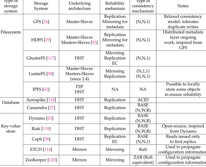
1.3 Overview of different distributed storage systems and their characteristics. . . 32
2.1 CPU utilization efficiency average for Get requests . . . 60
2.2 CPU utilization efficiency average for Post requests . . . 60
4.1 Throuput per client without RS3, with RS3, and with W-RS3, with batch budget= 24KB. . . 98
5.1 Simulation Parameters Settings . . . 111
5.2 Functions performed by storage servers when receiving a re-quest. . . 115
List of Abbreviations
ACID Atomicity, Consistency, Isolation and Durability
ACK Acknowledgment
ACL Access Control List
AFS Andrew File System
AFP Apple Filing Protocol
API Application Programmable Interface
BASE Basically Available, Soft state, Eventual consistency
BIER Bit Indexed Explicit Replication
BUSE Block device in User-space
CAP Consistency , Availability, Partition-resiliency
CBQ Class-Based Queuing
CDN Content Delivery Network
CFQ Completely Fair Queuing
COW Copy On Write
CPU Central Processing Unit
CRUSH Controlled Replication Under Scalable Hashing
CSI Container Storage Interface
DHT Distributed Hash Table
DPDK Data Plane Development Kit
DRAM Dynamic Random Access Memory
EC Erasure Codes/Erasure Coding
ECMP Equal Cost Multi-Path
FCP Fibre Channel Protocol
FIOS Flash I/O Scheduler
GFS Google File System or Global File System
HDD Hard-Disk Drive
HDFS Hadoop Distributed File System
HTTP Hyper Text Transfer Protocol
ICN Information Centric Networking
I/O Input/Output
I/Ops Input/Output per second
iSCSI internet Small Computer System Interface
LAN Local Area Network
LRU Least Recently Used
MDS Maximum Distance Separable
MG Metadata Group
MN Metadata Node
MRC Monotonic Read Consistency
MWC Monotonic Write Consistency
NBD Network Block Device
NFS Network File System
NoSQL Non SQL or Not only SQL (see SQL)
NVMe Non-Volatile Memory express
N2OS Network-Native Object Store
ON Orchestrator Node
OPCISS Optimized Predictive Container Image Storage System
OSD Object Storage Dæmon
PACELC Partition: Availability or Consistency, Else: Latency or Consistency
PCIe Peripheral Component Interconnect express
PG Placement Group
P2P Peer-to-Peer
QoS Quality of Service
QUIC Quick UDP Internet Connection Protocol
RADOS Reliable Autonomic Distributed Object Store
RAID Redundant Array of Independant Disks
RAM Random Access Memory
RDMS Relational Database Management System
RGC Regenating Codes
RPM Revolutions Per Minute
RS3 Request Scheduler for Storage Servers
RTT Round Time Trip
RYWC Read Your Writes Consistency
SaaS Storage as a Service
SATA Serial AT Attachment
SDS Software Defined Storage
SFQ Start-time Fair Queuing
SFQ(D) Depth-based Start-time Fair Queuing
SLA Service Level Agreement
SMB Server Message Block
SN Storage Node
SPDK Storage Plane Development Kit
SQL Structured Query Language
SR Segment Routing
SRLB Segment Routing Load Balancing
SSD Solid-State Drive
TCP Transmission Control Protocol
UDP User Datagram Protocol
VFS Virtual File System
VIP Virtual IP
VM Virtual Machine
VPP Vector Packet Processing
WFQ Weighted Fair Queuing
WFRC Write Follows Read Consistency
Introduction
Motivations
More than two decades ago, the first distributed storage systems were born in an attempt to guarantee that important data would never be lost and would always be available, in a more convenient way than just regular backups.
The vast majority of distributed storage systems follow the same pattern: they are designed to run on numerous cheap, unreliable and generic devices, composed of multiple storage disks, a processor, a network interface, and sometimes some additional memory. The software of these systems orga-nizes these devices in clusters, distributes data among servers, and generally makes sure that failures have the least possible impact on the cluster’s per-formance. However, the landscape of storage has shifted in numerous ways in the last few years.
First, for more than a decade, storage hardware has lagged behind its CPU, memory and network counterpart after Hard Disk Drives (HDDs) hit their mechanical limitations at 15K Revolutions Per Minute (RPM). How-ever, with flash memory becoming more and more available and perfor-mant –even outpacing Moore’s Law [1]–, this physical bottleneck has been removed. Unlike HDDs that are slow and have a high latency (∼5−15ms) as well as a low Input/Output per second (I/Ops) (∼ 50−200 depending on the rotational speed and bus type [2]) because of the spinning mechan-ical parts, Solid State Drives (SSDs) provide a better throughput as well as a much lower access latency (∼ 0.05−0.2ms [3]). This is even more true for Non-Volatile Memory express (NVMe) – SSDs that are accessible through PCI-express (PCIe) bus rather than Serial AT Attachment (SATA) – that can yield multiple hundred thousands I/Ops for a throughput of several Giga-bits per second (Gbps) [4].
Furthermore, the ever-increasing flash memory quality and affordability means that the HDD and SSD price curves are expected to keep drawing closer or even to cross in the next few years as shown in figure 1. Com-bined to the DRAM throughput evolution compared in figure2to its storage and network counterpart, the natural consequence is that the traditional stor-age software – aimed at working around previous HDD bottlenecks – has to evolve to adapt to shifting bottlenecks. Notably, new generation NVMe makes traditional interrupt-driven I/O highly uneffective with regard to CPU consumption [6]. Additionally, an increase in remote storage (accessed by the
Figure 1: SSD and HDD cost evolution prediction, as pre-sented in [5].
network) performance will also come at the cost of dedicating more network-ing hardware than what was traditionally deployed: where a 10GbE adapter was enough to saturate tens of HDDs on dedicated storage servers, 2 NVMe drives can more than saturate such an adapter [7].
Second, the way storage itself is organized and accessed has evolved in the two last decades. Where applications were deployed on individual servers and accessed local disks and filesystems, storage and compute are now separate entities. Most storage devices are assembled in large-scale clus-ters that run distributed databases, key-value stores or distributed filesys-tems, that in turn are shared between many services and applications to leverage economies of scale. These storage layers themselves have evolved and range from highly consistent databases working on very structured data to eventually consistent object stores storing data without any pattern.
Third, the amount of data to be stored grows exponentially, posing se-rious scalability issues: 90 % of the data stored by humanity has been gen-erated in the last two years [8], and big companies have been storing and processing petabytes of data for years now (see table1).
Furthermore, this exponential growth in quantity has been coupled with an ever increasing demand for fast services, becoming a real business issue for these companies: Amazon revealed that a 100ms increase in reponse time
Figure 2: Network, Storage and Memory hardware through-put evolution, as illustrated in [1].
on their platform induces a 1% drop in associated sales [20]. Likewise, in-creasing the load time of a page with 10 different google search results con-taining 30 entries from 400 too 900ms decreased Google’s advertising rev-enues by 20% [21]. The same has been shown to be true for every web-related business company [22]. This rapid change of scale drove big tech companies to develop their own storage backend during the mid-2000’s: Amazon with DynamoDB [23], Google with GFS, BigTable and Spanner [24, 25, 26], Face-book with Cassandra [27] and others like Ceph and Apache HDFS [28,29].
However, these new architectures that bloomed in the 2000’s are showing their limitations now that the order of magnitude of storage and performance required has increased again [30, 31, 32]. There are two recurring issues in these architectures: Estimation of data stored Estimation of data processed daily Google [9,10] 15 000 pb 100 pb NSA [11,12] 10 000 pb 29 pb Baidu [13] 2 000 pb 10-100 pb Facebook [14] 300 pb 600 Tb eBay [15,16] 90 pb 100 pb Sanger (DNAsequencing) [17,18] 45 pb 1,7 Tb Spotify [19] 10 pb 64 Tb
Table 1: Estimation of data stored and processed daily by big tech companies.
• Heavily layered software: A high number of software layers leads to two undesirable consequences: the overhead in CPU utilization can ac-tively impact performance on the storage server side and add latency to transactions, and reduce the efficiency of data transfer between the stor-age device and the network –for example because of unneeded mem-ory copies. While this impact was almost negligible with HDDs, this is not the case anymore. This is why, for instance, Ceph has launched its project Crimson in 2018 to modernize its implementation and improve its performance by reducing the computing and memory overhead of different members of its architecture [33,34].
• Architectural limitations: There are two – generally exclusive – types of architectures that are generally at fault. On one side, DHTs – initially used to avoid a central bottleneck and point of failure – are inherently not flexible and not well-suited to store varied types of data in vari-ous storage devices in the same cluster because they rely on pure flat data addressing. Furthermore, they react poorly to topology changes –which become common occurences when the number of participating storage nodes increases to follow the data growth. On another side, centralized architectures that rely on a central node and a master/slave architecture do not scale for obvious reasons. In these architectures, a single master has a full knowledge of the data placement, access control ... and is on the path of every storage request.
Thus we argue that storage systems must be rethought to overcome these techonological evolutions.
Contributions
The present dissertation has two aims: to propose a distributed storage archi-tecture overcoming the technical and structural limitations found in present deployed software, and to optimize specific storage mechanisms in order to improve scalability, performance, or flexibility of storage systems.
To this end, I initially give a broad description of the state of the art for storage systems in chapter 1: how they evolved in the last decades, what challenges they faced, what solution they proposed to tackle their issues as well as what theoretical framework they put in place to describe their prob-lematics.
In chapter2, I describe in depth 6Stor, a distributed object store that we created from the ground up during my Thesis and which architecture over-comes traditionnal limitations of such distributed storage systems. The way a 6Stor cluster functions is described, including its reaction to failures, its re-liability mechanisms as well as its consistency schemes. A set of benchmark is presented as well as an analysis of the performance impact of some design
decisions. The work presented in this chapter has been presented as a poster, been published as a workshop paper, and is the object of an accepted jour-nal jourjour-nal paper not yet published. Moreover, a Cisco techfund project was funded for a year to implement and improve 6Stor under the name Network-Native Object Store (N2OS). Two related patents are currently pending in the US patent office.
Chapter3presents two extensions made to the initial design of 6Stor dur-ing the tech fund. The first section describes how we implemented a block device on top of 6Stor’s object store. The second section presents mecha-nisms leveraging 6Stor’s IPv6 capabilities and segment routing to improve load balancing and latency. It is the object of a patent pending.
Chapter 4 describes a Request Scheduler for Storage Servers (RS3). RS3 adapts well-known network and compute scheduling algorithms to storage. It is designed to help services and applications share storage in two ways: it ensures that applications and services contending for storage are all allocated a fair share of the throughput, and it suppresses a usual problem in shared storage systems where small requests take a disproportionate amount of time to complete when they are processed in parallel with larger requests. RS3’s algorithm is described in details, and the throughput and response time of several patterns of requests sent to two similar implementations of storage servers –one incorporating RS3 and the other not– are analyzed to verify that the aforementioned issues are tackled. A paper presenting RS3 is soon to be submitted, and a relateddefensive publicationwas issued by Cisco.
Chapter 5 explains how to leverage the caching capabilities of regular storage servers when they are used to deploy distributed storage systems using erasure codes as their reliability mechanisms. Simulations show that locally handling data fragment like traditionnal files on servers leads to un-optimized cache usage. A straightforward way to handle this problem is proposed and its impact evaluated. The work presented in this chapter is soon to be submitted as a workshop paper and is the object of a patent pend-ing.
Finally, appendixA describes work towards incremental improvements with regard to container downloading and execution that was partially made in the context of a research internship and is the object of a patent pending, while appendixBdescribes how to build a storage server taking advantage of a user-space network stack to deliver high performance. That work was also the object of a research internship and is also the object of a patent pending.
Chapter 1
What you should know about
distributed storage systems
The need for distributed storage systems has driven both industry and academia to innovate on this subject for the last 30 years. This chapter presents a brief overview of the different types of architectures that have been developped in this context, and their strenghts and limitations. It also presents the different issues and tradeoffs inherent to the distributed nature of those storage sys-tems, what solutions exist to solve these. We also show how different systems make different choices in order to provide some guarantees for applications or filesystems running on top of them.
Section1.1describes the underlying architectures that serve as a backend for most distributed storage systems, and the impact their inherent structure has on their performance, reliability and flexibility. Section1.2explains how distributed storage systems guarantee that data is not lost and is available, even in case of failures, while section1.3explains how they deal with the pos-sible inconsistency when multiple copies of same data objects do not match. Finally, section1.4presents a non-exhaustive list of widely used distributed storage system and their characteristics with regard to the previous sections.
1.1
The different types of distributed storage
sys-tem architectures
Distributed storage architectures are numerous and span widely different scales, from a few servers to tens of thousands. Some storage systems are composed of loosely connected anonymous servers while others are central-ized organizations with a single master node that has full knowledge and authority on the cluster. This section proposes a classification of storage clus-ters in 5 main families. This categorization is in no way the only one and some systems might even fit multiple families, but it has the merit of un-derlining the strength and limitations of each family. Because the storage systems adopting these architectures are varied (filesystems, SQL databases, key-value stores, object stores ...), we call data object the basic piece of data on which those systems operate (file, database entry, key-value pair, object ...) for the remainder of this chapter.
1.1.1
Network Attached Storage (NAS) and Storage Area
Net-work (SAN)
A NAS is the most basic form of distribution with regard to storage. It is simply a storage device accessible through a Local Area Network (LAN), usually though an operating system on a host server. It is a commonly used way to share data among users or computers and as a storage backend for de-vices with small storage dede-vices. The Network File System (NFS) [35], Server Message Block (SMB) [36] and Apple Filing Protocol (AFP) [37] are the most popular protocols used to interact with a NAS. Even though the first version of NFS was developped in 1984, these protocols are still widely in use today. NAS are often used by clients as remote filesystems with a local mount point. More intricate versions of multi-NAS systems include the Andrew File Sys-tem (AFS) [38] and other filesystems inspired by it such as OpenAFS [39], the Coda File System [40], Intermezzo [41], etc.
While most NAS are regularly backed up, thus offering some kind of re-liability in the face of hardware failure, they are still usually composed of a single storage device or server, which is a throughput and capacity bottle-neck. Furthermore, data transfers take place on the LAN and depending on the use-case, it can take a large part of the available throughput.
Therefore, the 1990’s saw the emergence of Storage Area Network (SAN) technologies. A SAN is a network purely dedicated to storage. It is com-posed of several storage devices that are interconnected through dedicated links. These links are most often fibre channel or ethernet, with the servers running the Fibre Channel Protocol (FCP) or the internet Small Computer System Interface (iSCSI) protocol. While SANs are performant, they are also not flexible and require a dedicated infrastructure that is hard to scale. Un-like a NAS, SANs operate at the block level (rather than filesystem).
Both NAS and SAN architectures are illustrated in figure1.1.
1.1.2
Peer-to-Peer (P2P) networks
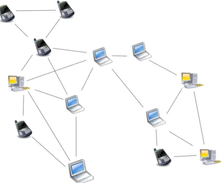
On the opposite spectrum of NAS and SANs that are local architectures, P2P networks aim at regrouping a large number of anonymous nodes to store and distribute data on a large scale. The first generation of P2P networks that arose around 2000 –Freenet[42, 43], Gnutella [44], Kazaa [45] etc ... – is composed of unstructured networks formed by nodes that randomly form temporary connections to each other rather than follow a global structure, as illustrated in figure1.2. These systems are designed to be robust to a high churn rate, notably by keeping data blocks on numerous users that in turn share these blocks with new arriving users. However, they are typically not performant as request for data are often flooded and are not sure to be met with success [46]. Furthermore, while popular data can usually be found
(a) NAS
(b) SAN
Figure 1.2: Example of an unstructured P2P network with ad hoc connections between nodes.
easily, cold data can often remain unreachable because the few nodes storing it are unavailable. It it thus not very well-suited for high reliability.
The second generation of P2P systems revolves around specific topologies that ensure that any node can efficiently route requests to files, even when the resource is rare. Chord [47], Kademlia [48] and Pastry [49] are examples of this approach, which use a Distributed Hash Table (see section 1.1.3) to construct the network overlay assigning resource ownership by consistent hashing (figure1.3). The consequence of this architecture choice is that they are less robust when the churn rate is high, because that implies frequent rebalancings, as explained in the next section.
1.1.3
Distributed Hash Tables (DHTs)
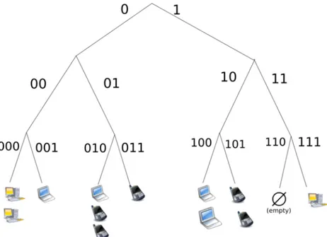
Distributed Hash Tables (DHTs) are the core of many distributed systems. A DHT is a decentralized distributed system associating pairs of (key,value). Re-sponsibility for mapping key to values and storing the values themselves is distributed amongst the nodes by assigning ranges of keys to specific nodes as illustrated in figure 1.4. DHTs are not necessarily storage systems, and should in a broader sense be viewed as a consistent way to map resource to servers holding them. As such, DHTs are at the foundation of multiple dis-tributed storage systems.
In a DHT, keys belong to a keyspace (usually n-bits strings or an equiv-alent) that is partitioned to split the keys between the nodes. An overlay network connects the nodes and allows them to find where keys belong. Typically, each data object stored is associated with a name that is hashed
Figure 1.3: Example of a structured P2P network using a DHT to identify nodes.
(for example using MD5 or any SHA hash function) to provide the key asso-ciated with data itself.
This overlay network is not necessarily a full mesh and queries might have to go through several nodes before reaching the relevant one. The av-erage number of connections to other nodes per node of a DHT is called its degree. A DHT composed of n nodes has a degree between 1 and n. A higher degree means that each node has more knowledge of the whole DHT and less redirections are needed for queries, but it also requires more synchroni-sation and has more memory footprint for DHT nodes. A common trade-off, used for example by Chord [47], is a degree of log(n)and an average number of redirection per request of log(n), for n nodes in the DHT. Table 1.1 sum-marizes the link between degree and average route length, as well as gives several examples of DHTs.
DHTs are designed to scale effectively with the number of participating nodes. However, the scalability of DHTs comes with negative consequences:
Unidimensionality: Because a standard DHT relies on a single-dimension keyspace, it reduces the characterization of a participating node to a single in-formation: the portion of the keyspace allocated to the node. In general, most systems relying on DHTs try to correlate this portion to the storage capacity of the node, so that every node is responsible for a portion of the keyspace equal or close to the proportion of its own storage capacity compared to the sum of the storage capacities of all participating nodes.
Figure 1.4: Example of the assignment of the Keyspace of 16-bits strings for a DHT composed of 4 nodes storing 20 equally
distributed data objects.
Degree Average
Route Length Used in Comment
O(1) O(1) Longest lookup
O(log(n)) O(log(n)) Chord [47], Kademlia [48]
Pastry [49], Tapestry [50]
Common but not optimal O(log(n)) O(loglog(log(n()n))) Koorde
Complex to implement and less flexibility for neighbours choice O(√n) O(1)
Requires constant synchronisation and more memory footprint
Table 1.1: Trade-off between degree and route length for DHTs.
This approach doesn’t allow for more complex storage systems incorpo-rating storage tiering (storage nodes with different type of storage devices such as HDD,SSD or NVMe). To do that, the storage system has to use differ-ent DHTs for differdiffer-ent storage tiers and keep track of which object is stored in which DHT. Furthermore, a simple DHT doesn’t accommodate the poten-tial heterogeneity in the performance of devices (outside of pure capacity) such as throughput and latency. Even though disparities between the same models of storage devices are not expected to be too high initially, they are expected to grow during the lifetime of a distributed storage system, when failed devices have to be replaced and other devices age differently. This issue has been raised for example in [51] and has led to developing fine-grained load balancing techniques when data is stored as multiple replicas in DHTs.
Finally, this uni-dimensionality also reduces the flexibility of storage sys-tems using them. Namely, a replication or erasure-coded policy has to be system-wide: it is not possible to store different objects under different rep-resentations (for example some replicated and some erasure coded) in a DHT.
Re-balancing: In a DHT, servers are assigned key ranges. In general, key ranges are evenly distributed among servers according to their capacity. Con-sequently, when a new server joins a DHT, key ranges are redistributed so that the new server takes its fair share of the load as illustrated in figure1.1.3
when adding a node to the DHT of figure1.1.3. This poses two difficulties. First, when key ranges change server assignment, all the data objects be-longing to these ranges have to be moved. In the ideal use case of perfect bal-ance and perfect reassignment (the only data moved is the data that the new node will serve), if we denote by c the capacity of the node, C the total capac-ity of the cluster with the new node and D the total amount of data stored in the DHT, an amount ofc∗SD data has to be transferred in average. Even worse, this is often not possible if the DHT has constraints on the keyspace assign-ment (for example contiguity requireassign-ments for DHT nodes): a key range re-assignment can lead to some key ranges being passed between two servers that were already in the DHT before, like illustrated in figure1.5. The trade-off is typically between aggregating the keyspace ranges assigned to nodes –leading to more data to rebalance– and optimizing the keyspace rebalancing –leading to keyspace disaggregation and more complexity.
Second, this re-balancing procedure has to be finished before the new node can serve requests and has to happen in parallel with the regular work-load of the DHT, if one doesn’t want to put it offline. This can lead to very long bootstrap time: in [23], Amazon states that the early iterations of their Dynamo key-value store had boostrap times as high as almost 24 hours when the rebalancing process had to be run in background during periods with in-tensive workloads. However, this can be prevented by a progressive key reassignment, at the cost of having the joining nodes only slowly getting
to their stable state. This approach has recently been pursued for example in Ceph since the Luminous release in 2017 with the upmap function, that allows to progressively assign bundle of objects to new servers when boot-straping [52].
Both these issues have been identified for a long time and can be attenu-ated or circumvented by adopting more complex structures : separate DHTs for different storage tiers, buckets in DHT-like architectures to isolate differ-ent parts of the cluster and allow them to be unavailable for a short time for a fast bootstrap etc... However, this adds complexity to systems implementing these workarounds, that require complex management planes.
1.1.4
Master-Slaves architectures
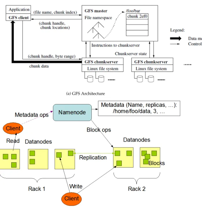
Where DHTs provide a distributed and consistent way to assign data objects to servers, master-slaves architectures put the burden of data placement and indexing on a master server. Requests to write or read data from the sys-tem must go through this master, either to decide where the data will be written or to know where to find it. Because data placement is not tied to consistent hash, it can be flexible and allow for more fine-grained policies than DHTs. Furthermore, having a single master reduces the complexity of concurrent operations, since the master can keep track of who is interacting with which data object. For this reason, distributed filesystems often rely on master-slaves architectures since operations on file can range from simple file creation to random writes in different places of the file. The Google File System (GFS) [24] and its open source counterpart, the Hadoop File System (HDFS) [29] adopt this architecture, as shown in figure1.6.
However, these single master architectures have an obvious scalability limitation. While efforts can be made to increase the number of concurrent client or amount of data that a single master server can handle, like in GFS where numerous optimisations were made (such as very large filesystem blocks – several MB instead of the traditionnal 4KB – and aggressive prefetch-ing), a point comes where the master can not handle too many clients. More-over, the single master is a Single Point Of Failure (SPOF). For this reason the master is often replicated on inactive masters ready to serve as fallbacks, but the transition period when a master fails can lead to cluster inactivity. These limitations have been observed and discussed both for GFS and HDFS [30,
31], pushing Hadoop to develop a distributed master layer for HDFS [53] and Google to develop a new distributed filesystem named Colossus [54] – on which there is no public information. There are many other single-master filesystems such as QFS [55], GPFS [56], the Global File System [57]...
For these reasons, some filesystems have begun resorting to multi-master architectures. For instance, the Lustre file system [58] supports Distributed Namespace (DNE) since its 2.4 release in 2013. DNE allows subdirectory
(a) Necessary rebalancing to match the new DHT Attribution.
(b) Stable state when rebalancing is done.
Figure 1.5: A rebalancing has to occur to ensure that data ob-jects are stored on their key’s newly attributed storage node.
(a) GFS Architecture
(b) HDFS Architecture
Figure 1.6: GFS and HDFS both have a single node dealing with all filesystem metadata operations: the GFS Master and
inode trees to be located on separate servers. Other examples of such archi-tectures include zFS [59], OrangeFS [60] or Farsite [61].
1.1.5
Summarize
Table1.2summarizes the characteristics of each type of architecture.
Architecture Type of Application Used in Comment NAS Shared local storage
Backup
NFS [35] AFS [38]
Easy to use/deploy SAN Enterprise storage
Used for performance
Requires dedicated infrastructure P2P Large scale file sharing
Decentralized storage Chord [47] Gnutella [44] IPFS [62] Weak guarantees Low performance Very large scale DHT Scalable enteprise storage
Various consistency schemes
DynamoDB [23] Cassandra [27] Ceph [28,63] Low flexibility Requires rebalancing High scalability Master-Slave
Mostly distributed filesystems Constrained environments Flexible GFS [24] HDFS [29] Not scalable Master bottleneck Can enforce strong constraints
Table 1.2: Summarize of the different types of architectures and their characteristics
1.2
Reliability in distributed storage systems
Most distributed storage systems are used for scalability but also for reliabil-ity: one advantage of deploying such systems on multiple servers is that one of these servers failing is not necessarily equivalent to data being unavail-able or worse, lost. There are multiple ways to ensure data remains availunavail-able when failures occur. This section presents the 3 main ones, that cover almost every distributed storage system. For the remainder of this section, we call reliability the capacity of a storage system to guarantee its data is available even in the face of failures, and storage overhead the ratio between the amount of data written on storage medium and the actual amount of data stored in the system, higher than 1 for reliable systems.
1.2.1
Mirroring
Mirroring is the most basic approach for reliability. It consists in maintaining copies of a full data set in several places. There are several approaches to mirroring but the most common one is backups. Often used in conjonction with NAS, regularly scheduled backups allow not to lose the bulk of data when a storage server fails. However, even incremental backups do not con-tain the data that has been generated/stored between the last backup and
the failure. Additionally, backups are used to restore systems, not for data to remain available after a server failure. As such, they offer neither strong reliability nor strong availability guarantees.
When stronger guarantees are required, which is usually the case in en-terprise environments, the mirrors take part in every storage operation (data write, change or deletion) that changes the data set so that the mirrors are an exact copy of the original data set. This is the case, for example, of the enterprise Microsoft Structured Query Language (SQL) Server [64], a Rela-tional Database Management System (RDBMS), when used in “hot standby” mode. In this mode, the mirror can – as its name implies – be hot swapped to continue operations when the principal server fails. However, these guaran-tees come at the cost of more latency for basic operations, since the mirrors have to acknowledge every operation before they are acknowledged to the clients rather than regularly lazily fetch the incremental changes.
Mirroring has the advantage of preserving the consistency inside a data set when it is required. It is a desirable property, notably for some SQL databases which have consistency rules between different data items that make them inter-dependant. However, mirroring does not allow for much flexibility since it is a straightforward one-to-one mapping between storage servers.
1.2.2
Replication
Another very common approach for reliability in storage systems is replica-tion: every data object is replicated on multiple storage nodes. The number of times every object is replicated is called the replication factor r and is of-ten configurable, with a replication factor of 3 being the industry standard. Replication differs from mirroring by its granularity: where mirroring dupli-cates an entire monolithic data set, replication duplidupli-cates copies of single data objects. It is usually used in larger storage systems where data sets are split on multiple storage nodes, whereas mirroring is generally used on databases spanning only a single node.
While mirroring is mostly used as a backup and hot swap technique, replication is sometimes used along with load balancing techniques to allow for smoother performance [65, 66]. However, with a better granularity than mirroring comes a more complex data placement management. Indeed, mir-roring architectures only need to know the list of mirrors which is typically just a few servers, whereas replication-based architectures must be able to know the location of replicas for every object. This is why replication is often used in DHT structures where every data object is associated with several keys, generally through a consistent hash mechanism so that a data object name is enough to know the locations of all its replicas. Furthermore, this mapping from data object name to key sets is often constrained for reliability
Chapter 1. What you should know about distributed storage systems 18
Background: 2-Step Placement
CRUS
H
RANDOM
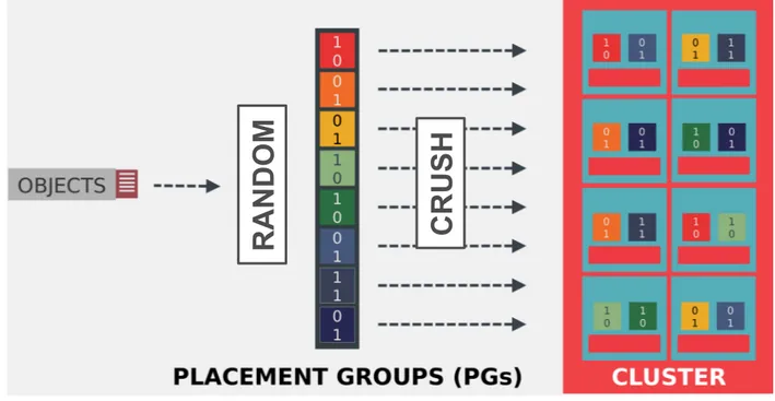
Figure 1.7: Ceph object-to-server two-step mapping: objects are uniformly mapped to PGs, themselves mapped to OSDs
following the rules of the CRUSH map
reasons.
For example, Ceph [28] assigns objects to Placement Groups (PGs) accord-ing to object name hashes with the Reliable Autonomic Distributed Object Store (RADOS) algorithm [63]. The number p of PGs of a storage pool is con-figured at storage pool creation, and every PG is randomly is associated with an ordered set of Object Storage Daemons (OSDs) following a Controlled Replication Under Scalable Hashing (CRUSH) map [67], each OSD being in charge of a disk partition on a storage node. Moreover, policies can be de-fined in the CRUSH map to ensure that OSDs assigned to PGs are physically located in different servers, racks, datacenters ... The first OSD assigned to a PG is called primary and is the “master” OSD of this PG: it is responsible for replicating data and is the one accessed for data retrieval (there is no load balancing). This two-step object-to-server mapping is illustrated in figure1.7. Thus, the number of PGs is decorrelated from – and usually much lower than – the number of possible combinations of n OSDs. This limits the num-ber of different sets of servers storing the same data. As a consequence, when r OSDs fail simultaneously, it is unlikely that any data is lost, since there is only a chance n(n−1)p...(n−r) that precisely those r OSDs are assigned to the same PG. However, more data is lost when this unlikely occurence happens. Augmenting p is thus a tradeoff between data loss probability in case of fail-ures and amount of potential data loss. Most large-scale deployments con-figure p<<n(n−1)...(n−r)since it is generally considered worse to often lose a small amount of data than to rarely lose a lot of data.
A
B
A+B
Figure 1.8: Inter-object erasure code with storage overhead of
1.5 capable of withstanding 1 disk failure.
1.2.3
Erasure Codes
Erasure codes (EC) find their inspiration in network codes, used in network transmissions in high loss rate or high latency environment to avoid packet retransmission, at the cost of a fixed overhead. They are the distributed storage system equivalent of local Redundant Array of Independant Disks (RAID) [68], and guarantee a higher reliability than replication techniques for a lower storage overhead. They are almost all derivations of the original Reed-Solomon codes used in many settings [69]. There are three different ways to erasure code data objects:
Inter-object erasure codes: In this approach, instead of purely replicating data objects, linear combinations of objects are stored in addition to objects themselves. When a disk fails and an object is lost, it is possible to rebuild it from the linear combination and the other object(s). The example shown in figure1.8 shows an inter-object erasure code with a storage overhead of 1.5 able to withstand 1 disk failure.
There are three issues with this approach: objects in the linear combina-tion have to be of the same size (or padding has to be added), objects have to be stored at the same time for the linear combination to be done (although it would be possible to initially store a pure replica of an object, then encode it with another object when one is stored – but it adds complexity to deal with the different possible “encoded states” of objects), and the linear combina-tions of objects have to be updated when either of the objects is modified or deleted from the system. Inter-object erasure codes are the equivalent of net-work codes [70,71] that combine data packets of same size to make sure the recipients can reconstruct data even when some packets are lost in the way.
Intra-object erasure codes: In this approach, objects are split in k fragments of same size that are used to generate k+r fragments of the same size as the original ones in a way that any k of the k+r encoded fragments can be used
A2
B2
A1+A2
B1+B2
A1
B1
Figure 1.9: Intra-object (2, 1)erasure code with storage over-head of1.5 capable of withstanding 1 disk failure.
to reconstruct the object. In most cases, the k original fragments, called the systematic fragments, are conserved in the k+r generated fragments – this is however not always the case, and some encodings, such as the Mojette Trans-form [72,73], notably used in the distributed file system RozoFS [74], do not store the systematic fragments directly. The r encoded fragments are called parity fragments and such a code is called a(k, r)erasure code. It follows that a (k, r) erasure code has a k+kr storage overhead and can withstand up to r failures. Figure1.9 illustrates this approach with a (2, 1) erasure code. The majority of distributed storage system using erasure codes choose this per-object approach.
Hybrid erasure codes: There exist a variety of other codes that stripe dif-ferent objects’ fragments and combine them to reduce the amount of data required for reconstruction or for other purposes. For example, the Hitch-hiker’s code [75], implemented in Facebook’s HDFS clusters, pairs different object “stripes” (corresponding to encoded fragments) and encodes them to-gether as proposed in [76] to reduce disk and network I/O for reconstruc-tions when compared to traditional Reed-Solomon codes. A simple example of such a hybrid code is illustrated in figure1.10.
1.2.4
Erasure codes and replication: what is the trade-off
In previous section we saw why erasure codes have a lower storage overhead than pure replication. However, they come with some drawbacks:
• The main drawback of erasure codes is the repair cost. In replicated setups, when a b bytes object’s replica is lost, another replica can be fetched to reconstruct it, effectively costing b bytes in both disk and network I/O. This is not the case for erasure codes, that require more bytes for reconstruction than the amount of data reconstructed. In the
A2
B2
A1
B1
A3
B3
A1+A2
B1+B2
A2+A3
B2+B3+
A1
Figure 1.10: Hybrid(3, 2)erasure code with storage overhead of5/3 capable of withstanding 2 disk failures.
examples of figures1.8and1.9, twice as much data as what is lost is re-quired when a disk fails (B and A+B if A is lost in the first case, A2/B2 and A1+A2/B1+B2 if the first server fails in the second case).
This is why, in addition to the “k out of k+r” repairability property, it is desirable for erasure codes to also have the Maximum Distance Sep-arable (MDS) property, minimizing the amount of fragments required to reconstructed missing fragments. Most of the work in the field aims at designing codes that minimize the required disk I/O, network I/O or both at the same time required for fragment reconstruction such as Regenerating Codes (RGC) [77, 78, 79, 80], hierarchical codes [81], or fountain codes [82,83,84].
• Storing data as encoded fragments requires computation. Most erasure codes use simple XOR operations but this is not always the case [72]. Moreover, since all data is not located on a single server, k separate con-nections usually have to be opened to retrieve the data, which is very impactful on storage systems where the network stack usually amount for a large portion of the CPU time used – more than 50% in some cases [85].
• Furthermore, there is added complexity in handling object fragments rather than replicas. First, it requires keeping track of more separate data entities since there are more fragments than object replicas. Sec-ond, every data operation requires the participation and synchroniza-tion of more servers. Finally, it is impossible or inefficient to make rel-evant local decisions since fragments represent only a fraction of the data. This complicates, for example, the caching strategies of erasure coded systems, as elaborated on further in chapter5.
For these reasons, some work has been done on hybrid erasure code/replication architectures [86] to obtain the best of both worlds. However, such approaches can inherently not have a storage overhead lower than 2.
1.3
Consistency and consensus
The previous section presented how distributed storage systems guarantee reliability in the face of failures. However, this comes with a significant draw-back: when several copies of data are stored in a storage system, it is hard to make sure that all replicas are consistent with each other. For the remainder of this section, we will suppose that our storage system is reliable through replication. However, most concepts discussed here could be translated in erasure coded setups with additional encoding steps.
First, it is important to make a distinction between consensus and consis-tency:
• A consensus is reached when all members of a storage system have the same version for the object replicas they store. For mirroring-based architectures, it is when all members store the exact same data. For replicaton-based architectures, it is when all replicas of every object are identical.
• Consistency is the ability of a distributed storage system to converge – slowly or quickly – towards a consensus. A storage system with strong consistency will quickly converge to a consensus whereas weak consis-tency means that such a consensus might not even be reached.
Throughout the last decades, there have been multiple theorems, for-mulations, acronyms ... describing consensus or consistency characteristics, guarantees or algorithms. These definitions often come from different back-grounds and sometimes even use the same words to describe different con-cepts, which can be confusing. This section aims at describing the most well-known definitions and concepts, what they entail and to what context they apply.
1.3.1
Theoretical frameworks
Consistency and Availability: the CAP theorem
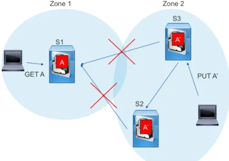
The CAP theorem – for Consistency Availability and Partition tolerance – is one of the most well-known theoretical result on distributed system. It for-mally formulates the intuitive fact that a distributed system that is split in two (or more) parts unable to communicate with each other can not provide availability for every operation on both sides of the separation and consis-tency in the request answers. For example, a data object which would be stored in a distributed storage system as multiple replicas either has all repli-cas on the same “side” in which repli-case it is unavailable on the other “side” or has replicas on both sides in which case it is impossible to ensure that a modification triggered on on side is propagated to the other, as illustrated in figure1.11.
Figure 1.11: Distributed storage system network partitioned in2 zones. In this case, the CAP theorem states that it is
im-possible to guarantee that object A is available in both zones and that all replicas of A are identical.
This intuition has first been formally described in [87] in 1999, presented as a conjecture in [88] in 2000, then proven, effectively becoming the CAP theorem [89] in 2002.
Formally, it states that a distributed data store can’t simultaneously pro-vide the three following guarantees:
• Consistency: Every data read receives either an error or the latest write. • Availability: Every request receives a valid response (with no
neces-sary guarantee of being the latest version).
• Partition tolerance: The system keeps operating when a partition hap-pens in the system. A partition is defined as an arbitrary number of messages being dropped or delayed between nodes composing the clus-ter.
Note that the consistency of the CAP theorem amounts to a consensus on every data object as defined in this section’s introduction. Because fail-ures are bound to happen, this theorem states that a distributed store has to choose between consistency and availability in the event of a partition. As explained in [90], this theorem has often been misinterpreted as the fact that data stores can not guarantee consistency and availability simultaneously under normal conditions. This is however not the case since a partition is not “normal conditions” for such a storage system.
This theorem can be misunderstood to justify why some distributed stor-age systems provide only eventual consistency instead of strong consistency (the consistency of the CAP theorem). It is perfectly possible for a distributed system to provide strong consistency and availability at the same time as long as there is no network partition, which represent only a fraction of failures [91]. However, systems providing only eventual consistency, even in normal conditions, do so because of another intrinsic tradeoff of distributed systems between consistency and latency.
This tradeoff has been explored in [92] and has led to an extension of CAP called PACELC. This acronym states that in the case of a Partition, a distributed system has to choose between Availability or Consistency (this is the usual CAP formulation), but Else, it has to choose between Latency and Consistency. This trade-off, while intuitive, will be further explained in sec-tion1.3.2.
Database characteristics: ACID and BASE
ACID (for Atomicity, Consistency, Isolation and Durability) is a set of prop-erties initially described in [93] (in 1981, without Durability) then in [94] in 1983 that, when they are verified by a sequence of database operations, de-fine a database transaction. A transaction can be perceived as a single logical operation on data, a typical example being a fund transfer between banks. These properties guarantee the following:
• Atomicity requires that the transaction either succeeds or fails. In other termes, operations in the transaction either all succeed or all fail, even in the case of errors, power failures or crashes.
• Consistency guarantees that a transaction changes the database from a valid state to another. This means that any constraint (such as the unicity of keys in a database) applying to the database can’t be violated by a transaction.
• Isolation ensures that concurrent transactions have the same effect on the database as if they were executed sequentially.
• Durability states that a committed transaction stays committed in the event of power loss, crash or error. This is mostly obtained by recording transactions on non-volatile memory before acknowledging the com-mit.
Even though ACID properties were not created with distributed systems in mind – ACID’s consistency derives from constraints between different ob-jects, not from differences between a single object replicas –, they can still apply to distributed databases. Moreover, I felt they were a worthwile inclu-sion in the list both to avoid confuinclu-sion on the different meanings of consis-tency and because another set of properties – called BASE and more relevant
![Figure 1: SSD and HDD cost evolution prediction, as pre- pre-sented in [ 5 ].](https://thumb-eu.123doks.com/thumbv2/123doknet/2647418.59822/21.892.128.739.124.545/figure-ssd-hdd-cost-evolution-prediction-pre-sented.webp)
![Figure 2: Network, Storage and Memory hardware through- through-put evolution, as illustrated in [ 1 ].](https://thumb-eu.123doks.com/thumbv2/123doknet/2647418.59822/22.892.182.681.126.521/figure-network-storage-memory-hardware-evolution-illustrated.webp)