Pour l'obtention du grade de
DOCTEUR DE L'UNIVERSITÉ DE POITIERS UFR des sciences fondamentales et appliquées
XLIM
(Diplôme National - Arrêté du 25 mai 2016)
École doctorale : Sciences et Ingénierie des Systèmes, Mathématiques, Informatique (Limoges) Secteur de recherche : Traitement du Signal et des images
Cotutelle : Nanchang University
Présentée par : Mengmeng Wang
Optical Image encryption based on apertured FrMT in the diffraction domain
Directeur(s) de Thèse :
Yannis Pousset, Clency Perrine, Nanrun Zhou Soutenue le 18 décembre 2019 devant le jury
Jury :
Président Philippe Carré Professeur, XLIM, Université de Poitiers
Rapporteur Christophe Charrier Maître de conférences, GREYC, Université de Caen-Normandie Rapporteur Zhengjun Liu Professor, Harbin Institute of Technology, China
Membre Yannis Pousset Professeur, XLIM, Université de Poitiers
Membre Clency Perrine Maître de conférences, XLIM, Université de Poitiers
Membre Nanrun Zhou Professor, Nanchang University, China
Membre François-Xavier Coudoux Professeur, IEMN, UPHF, Famars
Pour citer cette thèse :
Mengmeng Wang. Optical Image encryption based on apertured FrMT in the Diffraction domain [En ligne]. Thèse Traitement du Signal et des images. Poitiers : Université de Poitiers, 2019. Disponible sur Internet
THESIS
Pour l’obtention du Grade de
DOCTEUR DE L’UNIVERSITE DE POITIERS (Faculté des Sciences Fondamentales et Appliquées)
(Diplôme National - Arrêté du 25 mai 2016) Ecole Doctorale: SISMI
Secteur de Recherche: Traitement du Signal et des images
Présentée par: Mengmeng WANG
……… *********************************
Optical image encryption based on apertured fractional Mellin transform in the diffraction domain
**********************************
Directeur de thèse Yannis POUSSET, Clency PERRINE Co-Directeur de thèse Jianhua WU, Nanrun ZHOU
********************************** Soutenue le 18 décembre 2019 devant la Commission d’Examen **********************************
JURY
LIU Zhengjun Rapporteur, Harbin institute of Technology (China)
CHARRIER Christophe Rapporteur, GREYC lab. Université de Normandie
COUDOUX François Xavier, IEMN-Université Polytechnique de Haut de France
Yannis POUSSET Directeur de thèse, Université de Poitiers
Nanrun ZHOU Co-Directeur de thèse, Nanchang University (China) Clency PERRINE Co-encadrant de thèse, Université de Poitiers
Declaration
I hereby declare that except where specific reference is made to the work of others, the contents of this dissertation are original and have not been submitted in whole or in part for consideration for any other degree or qualification in this, or any other university. This dissertation is my own work and contains nothing which is the outcome of work done in collaboration with others, except as specified in the text and Acknowledgements. This dissertation contains fewer than 65,000 words including appendices, bibliography, footnotes, tables and equations and has fewer than 150 figures.
Mengmeng WANG December 2019
Acknowledgements
Firstly, I would like to express my sincere gratitude to all my supervisors, professor Yannis POUSSET, professor Philippe CARRE, and accociate professor Clency PERRINE as well as professor Jianhua WU and professor Nanrun ZHOU. They always gave me great help by providing consistent and illuminating guidances during my PhD’s studies. Without their encouragement and help, this thesis could not have reached its present form. Secondly, I would like to thank University of Poitiers and Nanchang University for giving me the opportunity and financial support of taking part in joint training of PhD thesis. Thirdly, I also show my appreciation to all the colleagues in Xlim institute of University of Poitiers and colleagues in department of information electronic engineering of Nanchang University.
I would like to express my special gratitude to my beloved family. My parents, Wang Henglu and Wang Chunju, always give me ceaseless care and support. I also feel grateful to my grandmother and little sister for their encouragement. I always obtain comfort from their unconditional love when I’m stuck in the place of feeling down.
Last but not least, I would like to thank my friends and classmates for their help in my study and life. Special thanks to Yu Fan, Xinwen Xie, Hai Liu, Sihang Liu, Weiping Zhou and Jiahan Liu for their help in my study and life.
This work was partially financed by the National Natural Science Foundation of China (grant numbers 61662047, 61861029).
Abstract
Apertures are not considered in most existing optical image encryption systems. However, apertures always exist in most practical optical systems. Hence, this thesis focuses on the study of introducing the aperture into optical fractional Mellin transform (FrMT) and its application in optical image encryption system. The feasibility of the proposed encryption schemes is verified by a series of numerical simulations. The main work is as follows:
Firstly, an optical image encryption scheme based on the fractional Mellin transform with a hard aperture has been proposed. The apertured fractional Mellin transform (apertured FrMT) can be performed through the log-polar transform and the optical apertured fractional Fourier transform. The side-lengths of the hard aperture serve as a key to improve the security and further increase the key space of the encryption system. This hard aperture is not only used to control the amount of light passing the lens by adjusting its size, but also reduces the leakage of light, which will, to some extent,
enhance the robustness against direct attacks.
Secondly, the Gaussian aperture, as a soft aperture for balancing between hard aperture and no aperture, is introduced into the apertured FrMT. With the Gaussian apertured FrMT in diffraction domain, a reality-preserving transform is proposed and used for image encryption. In this encryption scheme, for gray image, the Arnold transform and the bitwise XOR operation are also adopted to encrypt the image in order to enhance the security.
Finally, the encryption algorithm based on Gaussian apertured reality-preserving FrMT (GARPFrMT) used for color image is proposed. Besides, nonlinear GARPFrMT, color space rotation, together with 3D scrambling and bitwise XOR operation make the proposed color image encryption algorithm have good performance.
The simulation results have shown that the proposed encryption schemes are capable of resisting different common attacks and robust against noise and occlusion attacks.
cipher-text, nonlinear Gaussian apertured reality-preserving FrMT, Arnold transform; bitwise XOR.
Résumé
Les apertures ne sont pas considérées dans la plupart des systèmes d'encryption des images opticaux. Mais en fait, des apertures toujours existent dans la plupart des systèmes opticaux. Cette thèse se concentre sur l'étude de l'introduction de l'ouverture dans la transformation frationnelle de Mellin (TFrM) dans le domaine de diffraction et son application dans le système de cryptage d'images optiques. La faisabilité des schémas de cryptage proposés est vérifiée par une série de simulations numériques. Les travaux principaux sont les suivants:
Tout d'abord, un système de cryptage d'images optiques basé sur la transformation fractionnelle de Mellin avec une ouverture dure (TFrM à ouverture dure) a été proposé. La TFrM à ouverture dure peut être effectuée par la transformation log-polar et la transformation fractionnelle de Fourier à ouverture dans le domaine de diffraction. Les longueurs latérales de l'ouverture dure servent de clé pour améliorer la sécurité et augmenter encore l'espace clé du système de cryptage. Cette ouverture dure n'est pas seulement utilisée pour contrôler la quantité de lumière passant la lentille en ajustant sa taille, mais réduit également la fuite de lumière, ce qui, dans une certaine mesure, améliorera la robustesse contre les attaques directes.
Deuxièmement, l'ouverture gaussienne, comme une ouverture douce pour équilibrer entre l'ouverture dure et aucune ouverture, est introduite dans la TFrM à ouverture. Avec la TFrM à ouverture gaussienne dans le domaine de diffraction, une transformation de préservation de la réalité est proposée et utilisée pour cryptage d'images. Dans ce schéma de cryptage pour l'image en niveaux de gris, la transformation d’Arnold et l'opération d’XOR bitwise sont également adoptées pour cypter l'image afin d'améliorer la sécurité.
Enfin, l'algorithme de cryptage basé sur la TFrM à ouverture gaussian et de préservation de la réalité (TFrMOGPR) utilisé pour l'image couleur est proposé. Outre TFrMOGPR non linéaire, rotation de l'espace couleur, avec brouillage 3D et XOR
performer.
Les résultats de la simulation ont montré que les systèmes de cryptage proposés sont capables de résister à différentes attaques communes et robustes contre les attaques de bruit et d'occlusion.
Mots-clés: Cyptage d'image optique, ouverture dure, ouverture gaussianne, diffraction de Collins, TFrM à ouverture non linéaire, transformation fractionnelle de Fourier, codage de phase, ciphertext réel, TFrM non linéaire à ouverture gaussian et de préservation de la réalité, transformation d’Arnold, XOR bitwise.
Table of contents
List of figures ... x
List of tables ... x
Chapter 1 Introduction ... 1
1.1 Context and motivation ... 1
1.2 Purpose of the thesis ... 3
1.3 Thesis organization ... 4
Chapter 2 Fundamentals ... 5
2.1 Image encryption theory and research status ... 5
2.1.1 Image encryption theory ... 5
2.1.2 Research status of optical image encryption ... 6
2.2 Evaluation criterion of image encryption ... 10
2.2.1 Histogram analysis ... 10
2.2.2 Information entropy analysis ... 10
2.2.3 Correlation analysis ... 11
2.2.3 Mean square error and logarithm of mean square error ... 11
2.2.4 NPCR and UACI... 12
2.2.5 Robustness analysis ... 12
2.3 Chaotic logistic maps ... 13
2.3.1 Logistic map... 14 2.3.2 Tent map ... 14 2.3.3 Sine map... 15 2.3.4 Logistic-tent map ... 16 2.3.5 Logistic-sine map ... 16 2.3.6 2D logistic map ... 17 2.3.7 3D logistic map ... 17 2.3.8 Arnold transform ... 17
2.4.1 Fourier transform ... 18
2.4.2 Fractional Fourier transform ... 20
2.4.3 Fresnel diffraction ... 22
2.4.4 Optical fractional Fourier transform with lens... 24
2.4.5 Apertured fractional Fourier transform optical system ... 26
2.5 Fractional Mellin transform ... 28
2.5.1 Mellin transform ... 28
2.5.2 Fractional Mellin transform ... 29
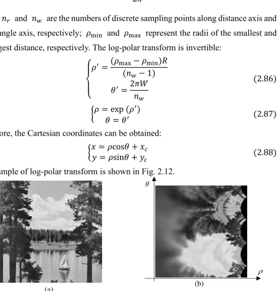
2.5.3 Log-polar transform ... 30
2.6 Summary ... 32
Chapter 3 ... 35
Image encryption based on the aperture FrMT ... 35
3.1 Introduction ... 35
3.2 Image encryption and decryption based on the apertured FrMT ... 36
3.2.1 Proposed fractional Mellin transform with aperture ... 36
3.2.2 Proposed image encryption and decryption scheme ... 38
3.3. Simulation results and analyses ... 40
3.3.1 Parameters setup ... 40
3.3.2 Encrypted results and decrypted images ... 40
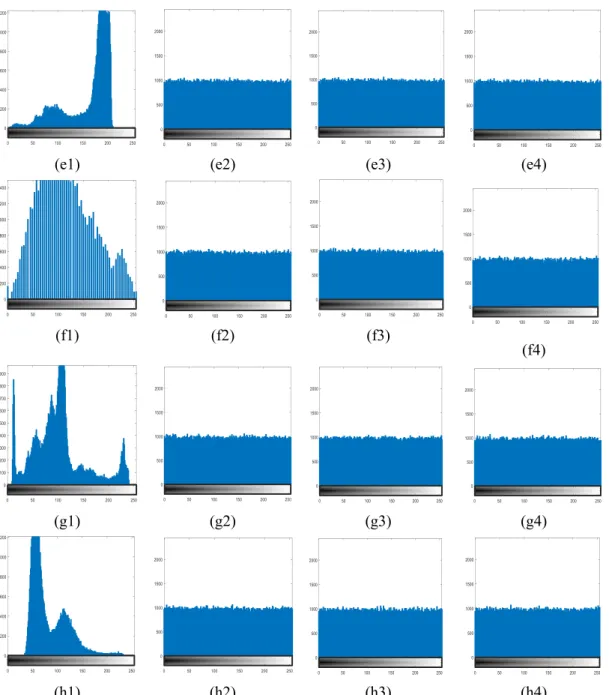
3.3.3 Histogram ... 44
3.3.4 Correlation of adjacent pixels ... 46
3.3.5 Key-sensitivity and key space analyses ... 48
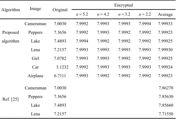
3.3.6. Information entropy analysis ... 55
3.3.7. Differential attacks ... 56
3.3.8 Noise attack and robustness analysis ... 56
3.4 Summary ... 59
Chapter 4 ... 60
Image encryption based on a reality-preserving Gaussian apertured FrMT ... 60
4.1 Introduction ... 60
4.2 Gaussian apertured FrFT optical system ... 62
4.3. Image encryption based on a Gaussian apertured reality-preserving FrMT . 64 4.3.1 Gaussian apertured fractional Mellin transform ... 64
4.3.2 reality-preservation of fractional transform ... 65
Table of contents iii
4.3.4 Decryption process... 67
4.4 Simulation results and security analyses ... 67
4.4.1 Parameters setup ... 67
4.4.2 Encryption results and decryption images ... 67
4.4.3 Histogram analysis ... 70
4.4.4 Correlation of adjacent pixels ... 72
4.4.5 Key-sensitivity and key space analyses ... 74
4.4.6 Information entropy analysis ... 76
4.4.7 Differential attacks ... 76
4.4.8 Robustness analysis ... 77
4.5 Color image encryption algorithm based on reality-preserving Gaussian FrMT ... 79
4.5.1 Color space rotation ... 79
4.5.2 Color image encryption algorithm based on RPGAFrMT ... 81
4.6 Experimental results and security analyses... 83
4.6.1 Parameters setup ... 83
4.6.2 Encrypted results and decrypted images ... 84
4.6.3 Histogram analysis ... 87
4.6.4 Correlation of adjacent pixels ... 90
4.6.5 Information entropy analysis ... 95
4.6.6 Differential attacks ... 96
4.6.7 Key-sensitivity and key space analyses ... 98
4.6.8 Robustness analysis ... 102
4.7 Summary ... 104
Chapter 5 ... 105
Conclusion and perspective ... 105
5.1 Summary of thesis... 105
List of figures
1.1 Chart for performing apertured FrMT and its inverse…..…..………3
2.1 DRPE optical security system……….6
2.2 The bifurcation diagram for the logistic map………..……..14
2.3 The bifurcation diagram for the tent map………..15
2.4 The bifurcation diagram for the sine map………..15
2.5 The bifurcation diagram of the logistic-tent………..16
2.6 The bifurcation diagram of the logistic-sine………..17
2.7 The diffraction aperture and observation plane……….23
2.8 Optical systems for performing the FrFT system………..25
2.9 An optical system for the apertured FrFT……….26
2.10 Chart for performing FrMT and its inverse………..………29
2.11 Log-polar transform: log-polar grid………..31
2.12 An example to show log-polar transform: (a) An original image of size 256 × 256. (b) The image in the log-polar coordinates with 500 rings and 500 wedges………...33
3.1 Optoelectronic hybrid setup for apertured FrMT……….37
3.2 Proposed image encryption and decryption algorithm……….38
3.3 Original images: (a) Elaine, (b) Cameraman, (c) Peppers, and (d) Baboon, (e) Airplane, (f) Bridge, (g) Milkdrop and (h) Lax………...………….41
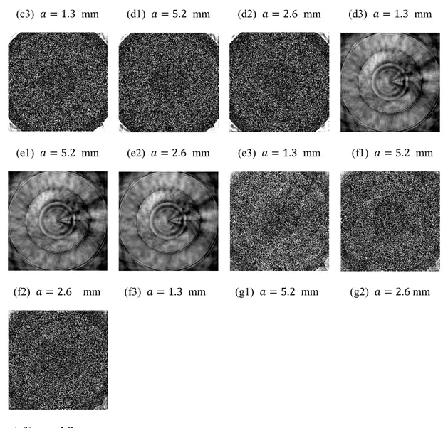
3.4 Encryption and decryption results for different side-lengths 𝑎, 𝑏 with 𝑎 = 𝑏: 𝑎 = 5.2, 2.6, 1.3, 0.6 , 0.3, 0.2, 0.1 mm. (a1), (b1), (c1), (d1), (e1), (f1), (g1), (h1) encrypted results for Elaine, Cameraman, Peppers, Baboon, respectively. (a2) - (a8) decrypted Elaine, (b2) - (b8) decrypted Cameraman, (c2) - (c8) decrypted Peppers, and (d2) - (d8) decrypted Baboon, (e2) - (e8) decrypted Airplane, (f2) - (f8) decrypted Bridge, (g2) - (g8) decrypted Milkdrop, (h2) - (h8) decrypted Lax.……….………....…...41
3.5 Histograms of original images (a1) Elaine, (b1) Cameraman, (c1) Peppers, (d1) Lake, (e) Airplane, (f) Bridge, (g) Milkdrop and (h) Lax. and histograms of encrypted images for different side-lengths of hard aperture: (a2), (b2), (c2), (d2), (e2), (f2), (g2) and (h2) for 𝑎 = 5.2 mm; (a3), (b3), (c3), (d3) (e3), (f3), (g3) and (h3) for 𝑎 = 2.2 mm; (a4), (b4), (c4), (d4), (e4), (f4), (g4) and (h4) for 𝑎 = 1.2 mm………..…….45
List of figures xi pixels in (a1) Elaine, (a2), (a3), and (a4) encrypted Elaine with 𝑎 = 5.2 mm, 𝑎 = 2.2 mm, 𝑎 = 1.2 mm, respectively (b1) Cameraman, (b2), (b3), and (b4) encrypted Cameraman with 𝑎 = 5.2 mm, 𝑎 = 2.2 mm, 𝑎 = 1.2 mm, respectively………..………48
3.7 Decrypted Elaine with incorrect keys with different side-lengths of the
aperture: (a1) - (a3) wrong apertured FrMT order, (b1) - (b3) wrong FrFT
order, (c1) - (c3) wrong outer radii, (d1) - (d3) wrong 𝜃𝑖, (e1) - (e3) wrong
𝜓𝑖 , (f1) - (f3) wrong wavelength 𝜆 , (g1) - (g3) wrong side-length
a………..49
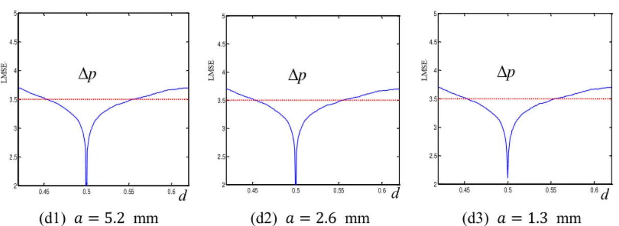
3.8 The deviations of LMSE curve of proposed scheme versus side-lengths of
aperture a………...……….51
3.9 LMSE curves with different aperture side-lengths for (a1) - (a3) 𝜃, (b1) - (b3)
𝜓, (c1) -(c3) 𝑞, (d1) - (d3) 𝑝……….…………..52
3.10 LMSE curve for the number of incorrect outer radii of the annular
domains………....52
3.11 Results of noise attack: (a1) 𝑘 = 50 , 𝑎 = 5.2 mm, (a2) 𝑘 = 50 , 𝑎 = 5.2
mm, (b1) 𝑘 = 50, 𝑎 = 2.6 mm, (b2) 𝑘 = 100, 𝑎 = 2.6 mm, (c1) 𝑘 = 50, 𝑎 = 1.3 mm, (c2) 𝑘 = 100, 𝑎 = 1.3 mm………...………57
3.12 Results for occlusion of encrypted data. Encrypted images with (a1) 1/4, (b1)
1/2, (c1) 1/8 occlusion. Under the different values of aperture widths, decrypted images for (a2), (a3), (a4) with 1/4 occlusion, decrypted images for (b2), (b3), (b4) with 1/2 occlusion, decrypted images for (c2), (c3), (c4) with 1/8 occlusion……….57
4.1 An optical system for the Gaussian apertured FrFT………..62
4.2 Normalized intensity distributions of Gaussian function for different standard
deviations 𝜎: 𝜎 = 1000, 500, 200, 100, 50, 10, respectively…………...63
4.3 Optoelectronic hybrid setup for apertured FrMT………..65
4.4 Block diagram of the encryption and decryption process……….66
4.5 Encrypted and decrypted results for different values 𝜎 : 𝜎 = 1000 , 500 ,
200 , 100 , 50 , 10 ; (a1), (b1), and (c1) are the original images: Elaine, Peppers, and Cameraman, Airplane, Lane and Lake respectively. (a2), (b2), and (c2) are the encrypted images. (a3) - (a8) are decrypted Elaine, (b3) - (b8) are decrypted Peppers, (c3) - (c8) are decrypted Cameraman, (d3) - (d8) are decrypted Airplane, (e3) - (e8) are decrypted Lane and (f3) - (f8) are decrypted Lake………..……….………..68
4.6 Histograms of original images (a1) Elaine, (b1) Peppers, (c1) Cameraman,
(d1) Airplane, (e1) Lena, (f1) Lake and histograms of encrypted images for different values 𝜎. (a2), (b2) , (c2), (e2) and (f2) for value 𝜎 = 1000; (a3), (b3) (c3), (d3), (e3) and (f3) for value 𝜎 = 500; (a4), (b4) (c4), (d4), (e4) and
(f4)for value 𝜎 = 100.……….………..……..…71
4.7 Graphical representation of correlations in horizontally adjacent pixels in (a1)
Elaine, (a2), (a3) and (a4) encrypted Elaine with 𝜎 = 1000 , 500, 100, respectively, (b1) Peppers, (b2), (b3) and (b4) encrypted Peppers with 𝜎 = 1000, 500, 100, respectively………73
4.8 Graphical representation of correlations in horizontally adjacent pixels in (a1)
Elaine, (a2), (a3) and (a4) encrypted Elaine with 𝜎 = 1000 , 500, 100, respectively, (b1) Peppers, (b2), (b3) and (b4) encrypted Peppers with 𝜎 = 1000, 500, 100, respectively………..………..74
4.9 MSE curves for (a) parameter 𝜇 + Δ01 , (b) initial value 𝑧0+ Δ02 , (c)
GARPFrMT order 𝑝0+ Δ03 , (d) incidence wavelength 𝜆 +
Δ04………75
4.10 Results of noise attack: The MSE curve for GARPFrMT with different values
𝜎……...………77
4.11 Decrypted Cameraman with various intensities of salt and peppers noises. At
the different values 𝜎 , decrypted images for (a1), (b1) and (c1) with 𝑘 = 0.01 , decrypted images for (a2), (b2) and (c2) with 𝑘 = 0.05 , decrypted images for (a3), (b3) and (c3) with 𝑘 = 0.1……….………77
4.12 Decrypted Cameraman with various occlusion ratios. Encrypted images with
(a1) 1/16, (b1) 1/8, and (c1) 1/4 occlusion. At the different values 𝜎 , decrypted images for (a2), (a3), and (a4) with 1/16 occlusion, decrypted images for (b2), (b3), and (b4) with 1/8 occlusion, and decrypted images for (c2), (c3), and (c4) with 1/16 occlusion………78
4.13 Schematic of the RGB color cube……….………79
4.14 RGB color cube……….…………...……80
4.15 (a) The original image Lena, (b) The rotated image with rotation angles 𝛼 =
𝜋/3, 𝜋/5, 𝜋/6………...………..…..81
4.16 The schematic of the color image encryption algorithm……….….……….81
4.17 The schematic of the color image decryption algorithm………….………..83
4.18 Color image encryption and decryption results: (a1)-(a2) Original image Peppers, House,
Cartoon, Baboon, Couple and Girl, (b)-(b7) encrypted image, (c)-(c7), (d)-(d7), (e)-(e7), (f)-(f7), decrypted images with correct keys for different values 𝜎..……….84
4.19 Histograms of the original and encrypted images at 𝜎 = 1000: (a1) - (f1)
Peppers, (a2) - (f2) Lena, (a3) - (f3) House, (a4) - (f4) Cartoon, (a5) - (f5) Baboon, (a6) - (f6) Couple and (a7) - (f7) Girl. Histograms of the original images in (a1), (a2), (a3), (a4), (a5), (a6) and (a7) R; (b1) (b2), (b3), (b4), (b5) and (b6) and (b7) G; (c1) (c2) , (c3), (c4), (c5), (c6) and (c7) B components, and its histograms of encrypted images (d1), (d2), (d3), (d4), (d5), (d6) and (d7) R; (e1), (e2), (e3), (e4), (e5), (e6) and (e7) G; (f1), (f2), (f3), (f4), (f5),
List of figures xiii
4.20 Self-correlations. Original image Lena: (a) R, (b) G, (c) B, encrypted image:
(d) R, (e) G, (f) B………..95
4.21 The decrypted images with incorrect rotation angles. (a) d𝛼 = π/180, (b)
d𝛼 = π/15 , (c) d𝛼 = π/2 , (d) d𝛽 = π/180 , (e) d𝛽 = π/15 , (f) d𝛽 = π/2 , (g) d𝛼 = d𝛽 = d𝜃 = π/180 , (h) d𝛼 = d𝛽 = d𝜃 = π/15 , (i) d𝛼 = d𝛽 = d𝜃 = π/2………..………..98
4.22 decrypted images with (a) only one incorrect fractional order 𝑝𝑅 = 0.55, (b)
two incorrect fractional orders 𝑝𝑅 = 0.55 , 𝑝𝐺 = 0.55 , (c) three incorrect
fractional orders 𝑝𝑅 = 0.55, 𝑝𝐺 = 0.55, 𝑝𝐵= 0.55,………….…….…..99
4.23 Decrypted images with (a) only one incorrect wavelength 𝜆R′ = 𝜆R+
5 × 10⁻⁷, (b) two incorrect wavelengths, 𝜆
R ′ = 𝜆
R+ 5 × 10⁻⁷, 𝜆G′ = 𝜆G+
5 × 10⁻⁷, (c) three incorrect wavelengths, 𝜆
R ′ = 𝜆 R+ 5 × 10⁻⁷, 𝜆G′ = 𝜆G+ 5 × 10⁻⁷, 𝜆 B ′ = 𝜆 B+ 5 × 10⁻⁷……….100
4.24 Results decrypted images with incorrect 𝑠1, 𝑠2, 𝑠3, 𝑠4. (a) incorrect 𝑠1 (𝛿 =
1 × 10⁻¹⁵ ), (b) incorrect 𝑠
2 ( 𝛿 = 1 × 10⁻¹⁵ ), (c) incorrect 𝑠3 ( 𝛿 =
1 × 10⁻¹⁵), (d) incorrect 𝑠
4 (𝛿 = 1 × 10⁻¹⁵); and MSE for the deviations
of (e) 𝑠1 , (f) 𝑠2 , (g) 𝑠3 , and (h) 𝑠4 for R, G, B
components………...………...100
4.25 Results of noise attack: The MSE curves for the three channels………….102
4.26 Decrypted images with various intensity of salt and peppers noises. At
different values 𝜎 , decrypted images for (a) and (c) 𝑘 = 0.01 , decrypted images for (b) and (d) decrypted images for (c) and (e) 𝑘 = 0.2……….…102
4.27 Decrypted Peppers with various occlusion ratios. Encrypted images with (a)
1/16, (f) 1/4 occlusion. At the different values 𝜎, decrypted image for (b) and (c) with 1/16 occlusion, decrypted image for (e) and (f) decrypted image with 1/4 occlusion……….….……….…103
List of tables
2.1 Arnold transform period……….…..19
3.1 Correlation coefficients between two adjacent pixels………..47
3.2 Key space of 𝜃, 𝜓, 𝑝, 𝑞………...…53
3.3 LMSE versus deviation =p 0.05 at order of FrMT p=0.3………...54
3.4 LMSE versus deviation =q 0.05 at order of FrFT q=0.7……….54
3.5 MSE versus deviation =p 0.05 at order of FrMT 𝑝 = 0.5 and Run time for different N………..54
3.6 Entropies of encrypted images for the proposed algorithm for different side-lengths (mm)………..……….……..55
3.7 The NPCR of encrypted images for proposed algorithms for different side-length (mm)....………...……….………..56
3.8 The UACI of encrypted images for proposed algorithms for different side-length (mm)……….………...………..56
3.9 LMSE for noise attacks for different side-length (mm)………57
3.10 LMSE for 1/8, 1/4 and 1/2 occlusion for different side-length (mm)……....58
4.1 Correlation between two adjacent pixels………..72
4.2 Comparison of entropies of original and encrypted images for different values 𝜎...76
4.3 NPCR (%) values of encrypted images for different values 𝜎………76
4.4 UACI (%) values of encrypted images for different values 𝜎……….76
4.5 Correlation between two adjacent pixels for R component of color image………..………..91
4.6 Correlation between two adjacent pixels for G component of color image…….………..…….92
4.7 Correlation between two adjacent pixels for B component of color image………..……..93
4.8 Comparison of entropies of R. G and B components of original and encrypted images for different values…..……….95
4.9 NPCR (%) values of three channels of encrypted images for different values 𝜎………...……….96
List of tables xi
4.10 UACI (%) values of three channels of encrypted images for different values
Chapter 1 Introduction
1.1 Context and motivation
Multimedia and network technique have been extensively involved in all aspects of life, and modern life has already entered an information age. It is inevitable for business, accounting, finance, education, health care and more areas to use the internet to transfer information in extremely productive ways. With the rapid development of computer and information technology in recent years, the forms of information expression turn out to be various and complex, among which, the expression of image information is widely used due to its strong intuitiveness and comprehensiveness. Hence, most information that we can access to each day is presented in the form of images [1]. Images as one of the most important carriers of information may involve personal privacy, business secrets, medical history, e-banking transactions, records etc. However, image information including personal and business privacy may be stolen by illegal users during transmission process in network, which causes information to be tampered, distributed illegally and revealed. Consequently, how to solve the security issues transmission or storage has become a great concern. Information security techniques have become a key technology for protecting digital information from harming and discriminating users' legal identity in the huge internet digital information society today. In fact, the network interaction between the sender and receiver must be confidential communication [2]. Image encryption technology is used to change the image from regular data state to unrecognizable one. Unlike text information, digital image has high redundancy and human eye recognition for gray scale is limited, hence, it is allowed that the digital image is distorted to some extent. Therefore, in view of some characteristics of digital image, the research on image encryption system can make the transmission technology of data encryption meet people’s expectations and demands for communication security, which has a very important social and economic significance.
interdisciplinary subject that rises in recent years due to its inherent distinctive characteristics, such as ability to process data in parallel and multi-dimensions [3-7]. In an optical system, all pixels in a two-dimensional image can be propagated and processed synchronously. The optical encryption device has more freedom than electronic encryption, and the information may be hidden in multiple freedoms. By calculation of the light interference, diffraction, filtering, imaging, holography and other processes, the involved wavelength, focal distance, amplitude, light intensity, phase, polarization, spatial frequency and optical element parameters are encoded to realize multi-encryption [3-8]. Hence, compared with traditional information security techniques based on computer cryptology, optical image encryption has significant advantages. What’s more, the optical encryption systems can be implemented not only by optical methods but also by digital cryptographic algorithms and systems based on the optical theory.
The optical image encryption system has been widely used and analyzed since double random phase encoding (DRPE) was first introduced into encryption system in 1995 [9], which greatly promotes the development of image encryption in optics field [3-12]. Some typically optical encryption systems in different domains have been proposed over the years, such as the Fourier transform (FT) [13-15], factional Fourier transform (FrFT) [16-22], Fresnel transform (FsT) [23-24], fractional Mellin transform (FrMT) [26-28], fractional random transform (FrRT) [29], canonical transform (LCT) [30], fractional cosine transform (FrCT) [31-35], fractional wavelet transform [36] and gyrator transform (GT) domains [37-39, 77].
The encryption algorithms based on FrFT have been a research hotspot, in which there have already many fruitful research results. There is a close relationship between the FrFT and Fresnel diffraction because the FrFT can be performed by Fresnel transform, which makes the FrFT be realized by optical methods. For the optical systems with lens, the FrFT can be achieved with the propagation of light wave and the Fourier lens. The lens is basic component in optical imaging and information processing systems, and the Fourier transform characteristics of lens is the basics of optical information processing, which makes the Fourier analysis effectively be applied in information optics. Hence, various encryption algorithms based on the optical FrFT have been proposed due to its representation property both in space and frequency domains with different orders. Generally, there are no apertures in optical image encryption systems. However, in practice, apertures always exist in most optical
2.1 Image encryption theory and research status 3
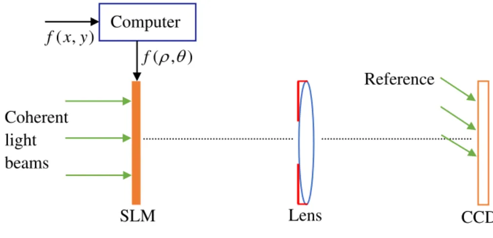
systems, such as the finite size of lens [40]. The implementation of the aperture can facilitate the reduction and control of light leakage in optical systems. Therefore, it is necessary and practical to analyze the performance of optical encryption systems with aperture. At the same time, to some extent, the linear FrFT-based encryption system has some potential security risks [41-42]. To avoid the disadvantages stemming from the linearity of classical optical system, it is also necessary to choose a nonlinear transform suitable for optical image encryption. The image encryption schemes proposed by Zhou are implemented by digital encryption algorithms, such as discrete fractional Fourier transform (DFrFT), reality-preserving transform in DFrFT domain [25-28], which does not fully demonstrate the characteristics of optical encryption. FrMT can be realized by log-polar transform and the fractional Fourier transform as shown in Fig. 1.1. Due to the nonlinearity of log-polar transform, FrMT also owns the nonlinear property, which reduces the potential insecurity caused by linear optical system. Thus, in this thesis, we focus on the apertured FrMT in diffraction domain and try to design new optical encryption algorithms in FrMT domain to encrypt the image.
Fig. 1.1 Chart for performing apertured FrMT and its inverse.
1.2 Purpose of the thesis
Based on the theories of image encryption, FrFT, Collins diffraction, apertured FrFT, reality-preserving transform, chaotic map and evaluation criterion of image encryption, the thesis studies the apertured FrMT, the reality-preserving apertured FrMT and its application in optical image encryption. The main purposes of the thesis are as follows:
1. Design of an apertured nonlinear fractional Mellin transform. The log-polar
transform and Collins diffraction equations with rectangle or circular hard aperture is utilized to perform apertured FrMT.
2. A new optical image encryption scheme based on apertured FrMT. An optical encryption algorithm based on apertured FrMT is designed. The influence of the size of the hard aperture on the key space will be analyzed. At the same time, the size of the hard aperture and the wavelength are designed as keys to increase the security of the encryption algorithm. The performance of the encryption algorithm will be analyzed.
3. An image encryption scheme based on Gaussian apertured reality-preserving
FrMT (GARPFrMT). A Gaussian aperture, like a soft aperture, is designed to perform Gaussian apertured FrMT to improve the amount of light that passes through the lens. What’s more, the reality-preserving transform in the diffraction domain will be constructed to ensure that the cipher-text is real, which is of convenience in display, transmission and storage.
4. A color image encryption scheme based on GARPFrMT. The proposed
GARPFrMT will be used in color image encryption algorithm to test its implementation in a three-channel optical system. The 3D logistic map serves to scramble the three channels. The simulation results of the proposed algorithm will be analyzed and discussed.
1.3 Thesis organization
This thesis is organized as follows: Chapter 2 provides fundamentals and the evaluation criterion of image encryption algorithm, the principles of the FrFT, chaotic system, fractional Fourier transform, Fresnel diffraction integral, apertured FrFT, Mellin and fractional Mellin transforms.
Chapter 3 proposes a new optical image encryption scheme based on apertured fractional Mellin transform. The apertured FrMT is performed by the log-polar transform and Collins diffraction equations with rectangle or circular hard aperture. The length of hard aperture is designed as the cipher key, and the influence of the side-length on the key space will be analyzed. The experimental results are analyzed and discussed, and the summary is presented at the end of the chapter.
Chapter 4 constructs the Gaussian apertured reality-preserving FrMT in the diffraction domain. An optical image encryption scheme based on GARPFrMT is proposed to improve the amount of light that passes through the lens and ensures that
2.1 Image encryption theory and research status 5 scheme. The simulation results verify the performance of the encryption algorithms.
Chapter 2 Fundamentals
Optical image encryption technology has attracted more and more attention of research due to its inherent distinctive characteristics, such as the ability of high speed for processing data in parallel. Compared with mathematical traditional information security and the computer cryptology, optical image encryption has many advantages, such as multi-dimensions, high-capacity, high design freedom, high robustness, parallelism and difficult to break [3]. This chapter introduces the image encryption theory, the research status of image encryption technology and the basic knowledge of image encryption. Due to the lack of space of thesis, the knowledge closely related to subsequent chapters is introduced briefly.
This chapter is arranged as follows: Section 2.1 introduces the image encryption
theory and research status of image encryption. Section 2.2 gives the evaluation criterions of image encryption algorithm. Section 2.3 describes the chaotic logistic maps briefly. The fractional Fourier transform is described in Section 2.4. The fractional Mellin transform is reviewed in Section 2.5. Section 2.6 summarizes the chapter.
2.1 Image encryption theory and research status
2.1.1 Image encryption theory
Image encryption technology is used to convert the original (plaintext) image to unrecognized quasi-random noise information, which protects effectively the image information. Researchers have proposed various image encryption methods with different safety performance. However, no matter which encryption method is utilized, the encryption results will fall into the following three categories: (1) Scrambling encryption. Scrambling encryption is the rearrangement of image pixels in space to convert the original image to be meaninglessly confused image. (2) Gray encryption. The encryption with only gray value change is called gray encryption. (3) Hybrid encryption. Hybrid encryption is the change of both the pixel position and the gray value.
2.1.2 Research status of optical image encryption
In optical encryption and decryption security field, in 1995, Refregier and Javidi [9] from University of Connecticut, United States, first proposed an optical image encryption method based on input plane and Fourier plane random encoding (double random plane encryption, DRPE), as shown in Fig. 2.1. In DRPE optical security system, the encrypted image can be obtained by using double random phase masks placed standard 4𝑓 optical signal processor. Let 2D random phases exp[i𝛼(𝑥, 𝑦)] and exp[i𝛽(𝑥, 𝑦)] denote masks 1 and 2, where i = √−1, the two random phases are in the range of [0,2𝜋]. First, the image 𝑓(𝑥, 𝑦) is multiplied by mask 1 placed in the input plane
𝑃(𝑥, 𝑦) = 𝑓(𝑥, 𝑦) exp[i𝛼(𝑥, 𝑦)] (2.1) Then 𝑃(𝑥, 𝑦) is modulated by mask 2 located in the Fourier domain
𝐻(𝑢, 𝑣) = FT{𝑃(𝑥, 𝑦)} exp[i𝛽(𝑢, 𝑣)] (2.2) Finally, the inverse Fourier transform (IFT) is performed, and the encoded image is captured by a CCD photo detector.
𝑂(𝜉, 𝜂) = IFT{𝐻(𝑢, 𝑣)} (2.3)
Fig. 2.1 DRPE optical security system [4]
Since DRPE was proposed by Refregier and Javidi, the optical security technology has become a very active area of image encryption [43-45]. Javidi and Nomura [46], in 2000, proposed an information encryption way based on the digital holographic and DRPE techniques. This security system allows the encrypted information to be stored, transmitted and decrypted digitally. Tajahuerce et al. [47] proposed an optoelectronic encryption method by combining the DRPE and digital phase-shifting interferometry, which makes the use of CCD capabilities more effectively and the complex information recorded fully. This technology also described the encryption process in the Fraunhofer or Fresnel diffraction domain.
In reality, the DRPE system are also used in different transform domains [11, 17-18, 24, 39, 47-49], such as the Fresnel, gyrator and fractional Fourier transform domains.
2.1 Image encryption theory and research status 7
Situ and Zhang, in 2004, proposed an optical encryption system using DRPE in Fresnel domain. In this security system, except the phase codes, the positions of the planes and the wavelength served as keys as well to achieve a higher security. In 2006, Chen and Zhao [49] proposed an encryption method for color images based on DRPE algorithm in Fresnel domain using wavelength multiplexing. Unnikrishnan [17], in 2000, proposed an optical architecture in fractional Fourier domain based on DRPE to convert the image into stationary white noise. Since this architecture was performed in fractional domain instead of Fourier domain, the orders of FrFT serve as keys, which further improves the security of the optical encryption system. Chen and Chang et al., in 2017, proposed an optical image conversion and encryption method by diffraction, phase retrieval and incoherent superposition in Fresnel domain. This method used phase iterative algorithms, which can greatly increase the system security.
However, it is proved that DRPE could be attacked under some conditions [51-53]. Therefore, many researchers have proposed various image encryption methods by combining DRPE and other algorithms to enhance the security of schemes. Singh and Sinha [30] proposed a multiple image encryption algorithm based on random phase masks generated by chaotic maps in canonical domain. This encryption algorithm combined the Kaplan-Yorke map and random phase masks to effectively enhance the key space. A double image encryption algorithm by utilizing an iterative random binary encoding in gyrator domain was proposed by Liu [48]. An information hiding method using DRPE and public-key cryptography was proposed by Sheng [54], which combines the complementary advantages of DPRE and Rivest-SHAMIR-Adleman encryption algorithms to improve the performance of security. Liu and Yu et al. [56] proposed encryption algorithm using cascaded FrFT and random phase filtering. Han [57] proposed an optical encryption method based on the exclusive-OR (XOR) operation and constructed an optical security system to perform the XOR operation.
By referring to the encryption methods using fractional Fourier transform, the concept of fractional order transform was generalized to design new image encryption technologies. Zhao and Li et al. [58], in 2009, proposed an optical encryption algorithm based on 2D generalization of the redefined fractional Hartley transform (FrHT) [22, 59-60, 81]. This encryption algorithm encrypted image using two fractional orders of FrHT and random phase codes (RPC). In addition, the fractional orders served as additional keys, which strengthened image security, and the feasibility of the proposed method was confirmed by computer simulations. Singh [79], in 2017, proposed an
optical encryption scheme in FrHT domain using Arnold transform and singular value decomposition. An optical image encryption method by combining Hartley transform (HT) and logistic map was proposed by Singh in 2009 [60]. This proposed technique using HT with jigsaw transform to solve the problem of bare decryption with HT, and the optical implementation of HT was given. The logistic map was used to generate chaotic random intensity mask. Ozaktas and Mendlovic et al. gave the relationship between the FrFT and wavelet transform (WT) in 1994 [61]. Mendlovic [62], in 1997, proposed the concept of fractional wavelet transform (FrWT) using association with both the wavelet transform and the fractional Fourier transform. And the optical implementation of the FrWT was given as well. A novel optical image encryption scheme using FrWT was proposed by Chen and Zhao in 2005 [36]. This novel method based on FrWT used the fractional orders and a range of scaling factors as keys. The image could be recovered only with all of these correct keys. At the same time, this method can also achieve the partial image encryption. Liu [78], in 2018, proposed an optical encryption based on compressed sensing in FrWT domain. Wu et al. [33-34, 63-64], proposed the encryption methods based on fractional cosine transforms (FrCT). Due to the relationship between the cosine transform and Fourier transform, the FrCT can be realized by optical implementation. In Wu’s methods, the FrCT was often combined with logistic maps to enhance the security.
Many image coding algorithms using optical interference technique were also proposed recently [65-70]. Niu [65], in 2010, proposed an encryption and verification algorithm using interference principle. This encryption process encodes two different images into three diffractive phase elements, and the wavelengths and distance parameters serve as keys. Cai [66], in 2015, proposed an asymmetric optical encryption method using coherent superposition. The equal modulus decomposition was used to construct a sufficient trapdoor one-way function to achieve a high robustness. An optical color image encryption based on phase-only encoding was proposed by Liu [67] in 2015. The components of color image were encoded into three phase masks using phase retrieval algorithm, and then the masks were placed in the input of Fresnel domains of three channels. The physical parameters of the optical system were used as keys. Due to the complex-value of output of most optical transform, the phase retrieval algorithm was applied into encryption schemes [12, 74-75]. Wang and Zhao [15], in 2011, proposed a multiple-image encryption using amplitude-truncation and phase-truncation. The phase truncated from complex-value based on
Rivest-SHAMIR-2.1 Image encryption theory and research status 9
Adelman algorithm was used as public keys. Wang [76], in 2014, proposed an optical asymmetric cryptosystem using phase-truncation in Fourier transform. The decryption keys were truncated from cypher text using modified amplitude-phase retrieval algorithm. An optical image encryption algorithm using phase retrieval algorithm in diffraction domain was proposed by Chen in 2017 [12]. Verma et al., in 2019, proposed an optical encryption algorithm using the phase retrieval and phase-truncated Fourier transforms.
The optical encryption systems can be implemented not only by optical methods but also by digital cryptographic algorithms and systems based on the optical theory. Pei et al. [80-88] proposed a series of discrete domains and its computation algorithms, such as discrete fractional cosine transform (DFrCT) and discrete fractional sine transforms (DFrST), discrete fractional Hartley transform, multiple-parameter discrete fractional Fourier transform [25-28, 88-92], random discrete fractional Fourier transform, which greatly improves the development of encryption algorithms. Liu [70-71] proposed a discrete random transform based on FrFT, which inherits the properties of discrete fractional Fourier. And Liu, in 2006, proposed an encryption scheme using discrete random cosine/sine transform.
To solve inconvenience for storage, transmission, or display caused by complex-value optical transforms, the reality-preserving transform was proposed in discrete domain [28, 63, 93-95]. Zhou [28], in 2012, proposed a color image encryption using reality-preserving FrMT. Wu [63], in 2013, proposed an image encryption scheme using a reality-preserving DFrCT. A color image encryption based on reality-preserving multiple-parameter FrFT was proposed by Lang in 2015 [94]. Zhao [58] proposed an optical image encryption scheme using redefined FrHT in 2008. The value of input and output are real, which is convenient for record, transmission and print. And the implementation of optical encryption system was proposed as well.
In recent years, the logistic maps have been used in image encryption [96-104]. Pareek [104], in 2006, proposed an image encryption algorithm based on logistic maps. In the proposed encryption, two logistic maps with an external secret key of 80 bits were used to meet the requirements of security. Many novel chaotic logistic maps were designed and applied in image encryption, such as logistic map, sine map, tent map, logistic-tent map, 2D logistic-sine map, 3D logistic map etc. [105-106].
In fact, most encryption algorithms based on FrFT optical systems are linear, which have some potential security risks to some extent [28]. Consequently, some nonlinear
encryption methods were proposed [15, 25-28, 107-109]. Liu [15] proposed a nonlinear phase-truncation algorithm for image encryption. Joshi [109] proposed a nonlinear image encryption scheme for color images, using natural logarithms and FrFT. Zhou et al. proposed a series of image encryption methods based on FrMT. Besides, the image encryption technique also combines with compressive sensing and a lot of results are published [27, 98, 110-113]. From above reviews, we can know that the image encryption technique has had a lot of research results with very important practical significance.
2.2 Evaluation criterion of image encryption
It is necessary to test the encryption system’s performance with statistical analyses. Those analysis methods are utilized to look for the internal relationship between the original image and the encrypted image. A good encryption algorithm can resist the statistical attacks. The common statistical analysis methods including histogram analysis, information entropy analysis, and correlation analysis. Besides statistical analyses, some other analyses are also very important for encryption systems, including the mean square error (MSE), logarithm of mean square error (LMSE), key space analysis and robustness analysis (such as noise and occlusion attacks).
2.2.1 Histogram analysis
The histogram is a very important analysis method used to describe the number of pixels in the image with different gray levels and their frequency of occurrence. The histograms of the original images usually are different, while those of cipher images obey a uniform distribution, by which the attackers cannot obtain useful information. 2.2.2 Information entropy analysis
In 1948, Shannon [114] proposed the concept of information entropy which is used
to describe how random the texture of an image is. Information entropy H solves the
problem of quantification of information and is defined as
𝐻 = ∑𝑛𝑖=1𝑃(𝑥𝑖)log2𝑃(𝑥𝑖) (2.4)
where 𝑃(𝑥𝑖) represents the probability of the occurrence of the pixels 𝑥𝑖 for an
2.2 Evaluation criterion of image encryption 11
probability of the occurrence of every gray level is equal: 𝑃(𝑥1) = 𝑃(𝑥2) = ⋯ =
𝑃(𝑥𝑛) = 1/𝑛. For example, the maximum is 8 for the encryption of a 256-graylevel
image. It is useless trying to attack the information entropy when the gray values of encryption image follow a uniform distribution.
2.2.3 Correlation analysis
There exist strong neighborhood correlations between adjacent pixels for the original images. However, to be secure and efficient, those neighborhood correlations should not exist for encrypted images. Therefore, it is necessary to perform a correlation analysis on adjacent image pixels in cipher and plain images. The correlation coefficient is defined as [115-116] 𝐶 = ∑ (𝑥𝑖 − 𝑥̅)(𝑦𝑖− 𝑦̅) 𝑁1 𝑖=1 √∑ (𝑥𝑁𝑖=11 𝑖 − 𝑥̅)2(𝑦𝑖 − 𝑦̅)2 (2.5) where 𝑥̅ = 𝑁1 1∑ 𝑥𝑖 𝑁1
𝑖=1 and 𝑦̅ =𝑁11∑𝑁𝑖=11 𝑦𝑖, 𝑁1 denotes the number of adjacent pixel
pairs chosen in the horizontal, vertical, and diagonal directions. The adjacent pixels have the strongest correlation when the coefficient 𝐶 is equal to 1, whereas, for 𝐶 = 0, those have no correlation. Thus, the closer the correlation coefficients of encryption images get to 0, the safer it is.
2.2.3 Mean square error and logarithm of mean square error
Tomeasure the similarity between the original image and the decrypted image, the
mean square error (MSE) and logarithm of mean square error (LMSE) are introduced to evaluate the quality of the decrypted images.
MSE is defined as [117] MSE = 𝑀1 1𝑀2∑ ∑[𝑓(𝑖, 𝑗) − 𝑓 ′(𝑖, 𝑗)]2 (2.6) 𝑀2 𝑗=1 𝑀1 𝑖=1
where 𝑓(𝑖, 𝑗) denotes the original image pixel, 𝑓′(𝑖, 𝑗) is the pixel of the decrypted
image, 𝑀1 × 𝑀2 are the size of original and decrypted images.
LMSE is defined as LMSE = log10{𝑀1 1𝑀2∑ ∑[𝑓(𝑖, 𝑗) − 𝑓 ′(𝑖, 𝑗)]2 𝑀2 𝑗=1 𝑀1 𝑖=1 } (2.7)
2.2.4 NPCR and UACI
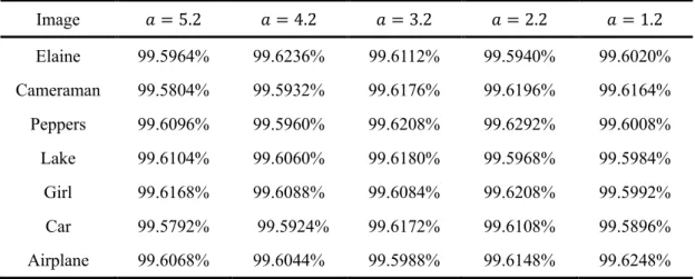
The attackers always try to find the relationship between two encrypted images whose original images have a 1-bit pixel difference by differential attack to obtain useful information. Thus, a reliable and secure encryption algorithm should be very sensitive to small change in the plain images. The Number of Pixels Change Rate (NPCR) and the Unified Average Changing Intensity (UACI) are two commonly used quantities to test the ability of an encryption algorithm to resist differential attacks. The NPCR and the UACI are, respectively, represented as [116-117]
NPCR = ∑ ∑ 𝐷(𝑖, 𝑗) ×𝑀100% 1× 𝑀2 (2.8) 𝑀2 𝑗=1 𝑀1 𝑖=1 UACI = [∑ ∑|𝐶1(𝑖, 𝑗) − 𝐶255 2(𝑖, 𝑗)|×𝑀100% 1× 𝑀2 𝑀2 𝑗=1 𝑀1 𝑖=1 ] (2.9) 𝐷(𝑖, 𝑗) = {0, 𝐶1, 𝐶1(𝑖, 𝑗) = 𝐶2(𝑖, 𝑗); 1(𝑖, 𝑗) ≠ 𝐶2(𝑖, 𝑗). (2.10)
where 𝐷(𝑖, 𝑗) is a bipolar. 𝐶1(𝑖, 𝑗) and 𝐶2(𝑖, 𝑗) are pixel values of encrypted images
of size 𝑀1× 𝑀2, whose original images have a 1-bit pixel difference.
For an ideal encryption system, the expected NPCR and UACI values of two arbitrary images can be obtained by the following equations:
NPCRE = (1 − 2−𝑡) × 100% (2.11)
UACIE = 212𝑡∑ 𝑖(𝑖 + 1)
2𝑡−1
𝑖=1
2𝑡 × 100% (2.12) where t represents the number of grayscales of the image. For an 8-bit grayscale image,
the NPCRE and UACIE are 96.6094% and 33.4635% , respectively, which means
that it is useless that the attackers analyze images by using differential attacks. 2.2.5 Robustness analysis
Robustness is used to measure a system’s ability that withstands or overcomes adverse conditions. In practical, since the cipher images are easily affected by noise and data loss during transmission and processing, it is necessary to measure the robustness of the proposed image encryption algorithm, noting that noise attack and occlusion
2.2 Evaluation criterion of image encryption 13
attack are two effective assessment methods.
The image usually is polluted by noise, like Gaussian noise and salt & peppers noise, during its collection, acquisition and transmission. Thus, a good encryption system must have an ability to resist noise interference, which means that although the encryption image to some extent was polluted with noise, the main information still can be obtained and recognizable with correct keys.
It is possible that the received and decrypted image comes across data loss due to network interruption or link congestion during signal transmission process. Therefore, it is necessary to study the effect of occlusion attacks on encrypted images. The encryption system is considered as a good one if the partially cropped cipher-text can be recovered to some extent with correct keys.
2.3 Chaotic logistic maps
Chaotic phenomenon is a kind of aperiodic, random-like, chance or irregular movement in deterministic system, which widely appears in the real world. Although chaotic phenomenon can be described in a nonlinear deterministic system, its behavior shows uncertainty, not repeatability and unpredictability. Generally, chaos stems from nonlinear dynamical system and nonlinear dynamical equation. In discrete domain, chaos can be shown as follows:
𝑥𝑛+1 = 𝐹(𝑥𝑛), 𝑛 = 0, 1, … (2.13)
where F can represent the nonlinear function. This dynamical equation that is
regarded as an iterative one may be performed repeatedly, in which the result of each iteration is used as the initial value for the next iteration shown as follows:
𝑥𝑛 = 𝐹𝑛(𝐹𝑛−1(𝐹𝑛−2⋯ 𝐹0(𝑥0))) (2.14)
In some cases, the behavior of the obtained sequence {𝑥0, 𝑥1, ⋯ 𝑥𝑛+1} will be
extremely complex. Chaos has been widely used in information encryption systems due to its several basic features: initial value sensitivity, parameter sensitivity, inherent randomness, and boundedness.
(1) Initial value sensitivity and parameter sensitivity
value or control parameter. The final result swings wildly in response to even a little change in initial value due to the magnifying effects of iteration equation.
(2) Inherent randomness
There exists pseudo randomness for inner behavior of the chaotic system, which is independent of the external environment.
(3) Boundedness
Although chaotic system is extremely unstable, its motion trajectory is always limited to a certain area. In other words, the motion trajectory is never out of system’s scoped areas, no matter how drastic the internal changes are.
In image encryption systems, several commonly-adopted chaotic maps are shown as follows.
2.3.1 Logistic map
The logistic map is a simple dynamic and widely used equation to produce a numerical sequence with a complex behavior, which is defined as [98, 117]:
𝑥𝑙+1= 𝜇𝑥𝑙(1 − 𝑥𝑙) (2.15)
where the iterative value 𝑥𝑙 belongs to (0, 1), 𝜇 ∈ (0, 4] is system parameter. It can
be seen that the logistic map is chaotic when 𝜇 is within [3.5699456, 4] as shown in Fig. 2.2.
Fig. 2.2 The bifurcation diagram for the logistic map. 2.3.2 Tent map
2.3 Chaotic logistic maps 15 𝑥𝑛+1 = { 𝜇𝑥𝑛 2 , 𝑥 ≤ 1 2 𝜇(1 − 𝑥𝑛) 2 , 𝑥 > 1 2 (2.16) where the parameter 𝜇 ∈ (0, 4]. The shape of tent map is like a tent in its bifurcation diagram as shown in Fig. 2.3 [119].
Fig. 2.3 The bifurcation diagram for the tent map. 2.3.3 Sine map
The behavior of sine system is similar with those of logistic or tent system as shown in Fig. 2.4 [105, 117]. The sine map is defined as:
𝑥𝑛+1 = 𝜇 sin(𝜋𝑥4 𝑛) (2.17) where the parameter 𝜇 ∈ (0, 4].
There are two problems in logistic and tent maps: (1) the chaotic range is limited, (2) the distribution of the variant density function is non-uniform. Therefore, [120] introduces several compound chaotic systems based on multiple model with excellent performance.
2.3.4 Logistic-tent map
The logistic-tent map is derived from logistic and tent maps, and its mathematical definition is given by [120] 𝑥𝑛+1 = { (𝑟𝑥𝑛(1 − 𝑥𝑛) +(4 − 𝜇)𝑥2 𝑛) mod 1, 𝑥 < 1/2 (𝑟𝑥𝑛(1 − 𝑥𝑛) +(4 − 𝜇)(1 − 𝑥2 𝑛)) mod 1, 𝑥 ≥ 1/2 (2.18)
where the parameter 𝜇 ∈ (0, 4], the operator ‘mod’ represents the modulo operation. The bifurcation diagram is shown in Fig. 2.5. It can be seen that its chaotic range is within (0, 4], which extends far beyond those of the logistic or tent maps. Besides, its iteration results uniformly distribute within [0, 1].
Fig. 2.5The bifurcation diagram of the logistic-tent. 2.3.5 Logistic-sine map
The logistic-sine system is obtained by logistic map and sine map, as defined [120]: 𝑥𝑛+1 = (𝜇𝑥𝑛(1 − 𝑥𝑛) +(4 − 𝜇) sin(𝜋𝑥4 𝑛)) mod 1 (2.19) where the parameter 𝜇 is within (0, 4]. Fig. 2.6 shows the bifurcation diagram of
2.3 Chaotic logistic maps 17
logistic-sine, from which it can be seen that its chaotic behaviors exist within the whole range (0, 4] and the output sequences distribute within [0, 1] uniformly.
Fig. 2.6The bifurcation diagram of the logistic-sine. 2.3.6 2D logistic map
The definition of 2D-dimensional Logistic system is as follows [121]
{ 𝑥𝑙+1= 𝜇𝑙𝑥𝑙(1 − 𝑥𝑙) + 𝛾1𝑦𝑙2
𝑦𝑙+1= 𝜇2𝑦𝑙(1 − 𝑦𝑙) + 𝛾2(𝑥𝑙2+ 𝑥𝑙𝑦𝑙) (2.20) where 𝑥𝑙 , 𝑦𝑙 belong to (0, 1), 𝑙 00, 1, 2…, and 𝜇1 , 𝜇2 , 𝛾1 , 𝛾2 are the system parameters. If the following conditions are met: 2.75< 𝜇1 < 3.4 , 2.75< 𝜇2 < 3.45 ,
0.15 < 𝛾1 < 0.21, 0.13 < 𝛾2 < 0.15, then the system exhibits chaotic behavior.
2.3.7 3D logistic map
The 3D logistic system is defined as [122-123] {
𝑥𝑙+1= 𝜆𝑥𝑙(1 − 𝑥𝑙) + 𝛽𝑥1𝑦𝑙2+ 𝛼𝑧𝑙3 𝑦𝑙+1= 𝜆𝑦𝑙(1 − 𝑦𝑙) + 𝛽𝑦1𝑧𝑙2+ 𝛼𝑥𝑙3 𝑧𝑙+1 = 𝜆𝑧𝑙(1 − 𝑧𝑙) + 𝛽𝑧𝑥𝑙2+ 𝛼𝑦𝑙3
(2.21)
where 𝑥𝑙, 𝑦𝑙 and 𝑧𝑙 are in the range of (0, 1), 𝑙00, 1, 2…, and when the conditions
3.53< 𝜆 < 3.81 , 0< 𝛽 < 0.022 , 0< 𝛼 < 0.015 are met, the system exists chaotic behavior.
2.3.8 Arnold transform
Arnold transform, a 2D chaotic map, is a widely used scrambling transformation in image encryption systems and its general form with 𝑎>0, b > 0 is [121]:
[𝑥𝑦′′] = [1𝑎 𝑎𝑏 + 1] [𝑏 𝑥𝑦] mod 𝑁 (2.22)
where [𝑥, 𝑦]𝑡 and [𝑥′, 𝑦′]𝑡 are positions of an N-order matrix element before and after
the Arnold transform, respectively, the operator ‘mod’ represents the modulo operation.
Since maximum Lyapunov exponent of the Arnold map is 𝜆 = 1 +𝑎𝑏+√(𝑎𝑏)2 2+4𝑎𝑏> 1,
which makes this 2D system always exhibit chaotic behavior [121].
When 𝑎00, 𝑏 = 1, the transform is the common Arnold transform shown as:
[𝑥𝑦′′] = [ 1−1 1] [1 𝑥𝑦] mod 𝑁 (2.23) And its inverse transform is given as:
[𝑥𝑦] = [−12 −11 ] [𝑥𝑦′′] mod 𝑁 (2.24) Arnold transform has a periodic feature, which makes the input of the transform return to its initial state after many times of iterations. Notice that the input with different size corresponds to different transformation period. For example, the period of the Arnold transform is 192 corresponding to the input with size 256×256 as shown in Table 2.1.
Table 2.1 Arnold transform period Input size Arnold transform period
128×128 96
256×256 192
512×512 384
1024×1024 768
2.4 Fractional Fourier transform
2.4.1 Fourier transform
The Fourier transform is a common mathematical method to analyze and synthesize signals. Any continuous sequence or signal can be expressed by superposition of sinusoidal signals with different frequencies. This method changes the signal from time domain to frequency domain. The continuous Fourier transform is defined as
2.4 Fractional Fourier transform 19
𝐹(𝜔) = 𝐹{𝑓(𝑡)} = ∫ 𝑓(𝑡)𝑒∞ −𝑖𝜔𝑡d𝑡 (2.25)
−∞
where 𝑓(𝑡) and 𝐹(𝜔) are named the Fourier transform pair, which can describe the same physical object in different domains (the time domain or the frequency domain). The inverse Fourier transform is shown as
𝑓(𝜔) = 𝐹−1{𝑓(𝑡)} = 1
2𝜋 ∫ 𝐹(𝜔)𝑒i𝜔𝑡d𝜔 (2.26) ∞
−∞ The 2D Fourier transform is defined as
𝐹(𝜉, 𝜂) = ∫ ∫ 𝑓(𝑥, 𝑦)exp[−i2𝜋(𝜉𝑥 + 𝜂𝑦)]d𝑥d𝑦∞ −∞ ∞ −∞ (2.27) Its inverse is 𝑓(𝑥, 𝑦) = ∫ ∫ 𝐹(𝜉, 𝜂)exp[i2𝜋(𝜉𝑥 + 𝜂𝑦)]d𝜉d𝜂∞ −∞ ∞ −∞ (2.28)
where 𝑥, 𝑦, 𝜉, 𝜂 are real variables.
The discrete form of the Fourier transform can be computed quickly using a digital computer. Its fast algorithm is called fast Fourier transform (FFT). The discrete Fourier transform and its inverse for a signal with length N are defined as
𝐹(𝑘) = 1 √𝑁∑ 𝑓(𝑛)𝑒 −i2𝜋𝑛𝑘𝑁 𝑁−1 𝑛=0 , 𝑘 = 0, 1, … , 𝑁 − 1 (2.29) 𝑓(𝑛) = 1 √𝑁∑ 𝐹(𝑘)𝑒 i2𝜋𝑛𝑘𝑁 𝑁−1 𝑘=0 , 𝑛 = 0, 1, … , 𝑁 − 1 (2.30) The 2D discrete Fourier transform and its inverse for a 2D signal 𝑓(𝑚, 𝑛) are expressed as 𝐹(𝑘, 𝑙) = 1 √𝑀 × 𝑁 ∑ ∑ 𝑓(𝑚, 𝑛)𝑒 −i2𝜋(𝑚𝑘𝑀 +𝑛𝑙𝑁 ) 𝑁−1 𝑛=0 𝑀−1 𝑚=0 , 𝑘 = 0, 1, … , 𝑀 − 1; 𝑙 = 0, 1, … , 𝑁 − 1 (2.31) 𝑓(𝑚, 𝑛) = 1 √𝑀 × 𝑁∑ ∑ 𝐹(𝑘, 𝑙)𝑒 i2𝜋(𝑚𝑘𝑀 +𝑛𝑙𝑁 ) 𝑁−1 𝑙=0 𝑀−1 𝑘=0 , 𝑚 = 0, 1, … , 𝑀 − 1; 𝑛 = 0, 1, … , 𝑁 − 1 (2.32)
The Fourier transform has linearity:
𝑎𝑓1(𝑛) + 𝑏𝑓2(𝑛) ⇔ 𝑎𝐹1(𝑘) + 𝑏𝐹2(𝑘) (2.33) The complex convolution operation can be simplified by the Fourier transform.
𝑓 ∗ 𝑔 = 𝐹−1{𝐹{𝑓} ∙ 𝐹{𝑔}} (2.34) where functions 𝑓 and g are absolutely integrable.
2.4.2 Fractional Fourier transform
FrFT has found many applications in optical signal processing and encryption. The
mathematical definition of FrFT was given by McBride and Kerr. Let 𝐹𝛼{𝑓(𝑡)}(𝑢)
denote the fractional Fourier transform of the function 𝑓(𝑡), thus the FrFT is defined as [59, 85-87]
𝐹𝛼{𝑓(𝑡)}(𝑢) = ∫ 𝑓(𝑡)𝐾
𝛼(𝑢, 𝑡)d𝑡 (2.35) ∞
−∞ where the transform kernel is given by:
𝐾𝛼(𝑢, 𝑡) = { 𝐴𝛼exp{i𝜋[(𝑢2+ 𝑡2)cot𝜙 − 2𝑡𝑢csc𝜙]}, 𝜙 ≠ 𝜋, 2𝜋 𝛿(𝑡 − 𝑢), 𝜙 = 2𝜋; 𝛿(𝑡 + 𝑢), 𝜙 = 𝜋 (2.36) and 𝐴𝛼 = exp [−i(𝜋sgn(𝜙)4 − 𝜙/2)] |sin𝜙|1/2 (2.37) where 𝜙 = 𝛼𝜋/2 with 0 < |𝛼| < 2, 𝛼 is the FrFT order and i is imaginary unit. If 𝛼 = 1, then Eq. (2.35) is equal to the conventional Fourier transform. Thus, FrFT can regarded as generalized Fourier transform. Since FrFT has ability to represent the signal in the spatial and frequency domains simultaneously, as the generalization of the Fourier transform, FrFT not only inherits the basic properties of the Fourier transform, but also owns the properties not available in the Fourier transform.
The 2D fractional Fourier transform with order (𝑝1, 𝑝2) is [146]
𝐹(𝑝1,𝑝2)(𝑢, 𝑣) = 𝐶 ∙ ∫ ∫ 𝑓(𝑥, 𝑦) ∙ exp { −2𝜋i (sin𝜙𝑢𝑥 1+ 𝑣𝑦 sin𝜙2) +𝜋i (𝑢tan𝜙2+ 𝑥2 1 + 𝑣2+ 𝑦2 tan𝜙2 )} d𝑥d𝑦 ∞ −∞ ∞ −∞
2.4 Fractional Fourier transform 21
(2.38) where 𝐶 is a constant, 𝜙1 =𝑝12𝜋 , 𝜙2 =𝑝22𝜋 . Observe that 𝐹(0,0)(𝑢, 𝑣) = 𝑓(𝑥, 𝑦) ,
which is equal to 𝑓(𝑥, 𝑦), and 𝐹(1,1)(𝑢, 𝑣) = 𝐹(𝑢, 𝑣), which is the Fourier transform
of 𝑓(𝑥, 𝑦).
The main mathematical properties of FrFT are shown as follows [125-126].
(1) Linear additivity
The linearity is a very important property for FrFT, which satisfies the superposition theorem:
𝐹𝛼{𝑐
1𝑓1(𝑡) + 𝑐2𝑓2(𝑡)}(𝑢) = 𝑐1𝐹𝛼{𝑓1(𝑡)} + 𝑐2𝐹𝛼{𝑓2(𝑡)} (2.39)
where 𝑐1, 𝑐2 are complex constants, 𝑓1(𝑡) and 𝑓2(𝑡) are arbitrary functions, α is
the order of FrFT.
(2) Fractional order additivity
The order of FrFT is additive:
𝐹𝛼𝐹𝛽 = 𝐹𝛼+𝛽 (2.40)
(3) Periodicity
The period of FrFT order is 4:
𝐹𝛼+4= 𝐹𝛼 (2.41)
(4) Reversibility
FrFT owns reversibility:
(𝐹𝛼)−1= 𝐹−𝛼 (2.42)
(5) Unitarity
The fractional Fourier operators are unitary:
(𝐹𝛼)−1= (𝐹𝛼)𝐻 (2.43) where H represents the conjugate and the transpose.
(6) Continuity
𝐹𝑐1𝛼1+𝑐2𝛼2{𝑓(𝑡)} = 𝐹𝑐1𝛼1𝐹𝑐2𝛼2{𝑓(𝑡)} = 𝐹𝑐2𝛼2𝐹𝑐1𝛼1{𝑓(𝑡)} (2.44)
where 𝑐1, 𝑐2 ∈ 𝑅, 𝛼1, 2 are the orders of FrFT.
(7) Shift properties
𝐹𝛼{𝑓(𝑡 − 𝑚)}(𝑢) = exp {i𝑚sin (𝛼𝜋
2 ) [𝑢 − 𝑚cos( 𝛼𝜋
4 )]} × 𝐹𝛼(𝑢 − 𝑚cos𝛼)
(2.45) The frequency shift characteristic:
𝐹𝛼{exp(i𝑡𝑣) 𝑓(𝑡)}(𝑢) = exp {−i𝑣cos𝛼 [𝑣sin𝛼
2 + 𝑢]} × 𝐹𝛼(𝑢 − 𝑣sin𝛼)
(2.46)
(8) Scale property
Changing the FrFT input signal in scale not only introduces a quadratic phase related to scale factor, but also changes the order of FrFT, as shown below:
𝐹𝛼{𝑓(𝑐𝑡)}(𝑢) = √1 − icot𝛼 𝑐2− icot𝛼 exp (i 𝑢 2 (1 − cos2𝛽 𝑐sin2𝛼) cot 𝛼) × 𝐹𝛽{𝑓(𝑥)} sin 𝛽 𝑐sin𝛼 𝑢) (2.47)
where 𝑐 ∈ 𝑅+, 𝛽 = arctan (𝑐2tan 𝛼).
2.4.3 Fresnel diffraction
Namias [126] established the fractional Fourier transform in 1980 and McBride and Kerr completed its theory in 1987. In the early 1990s, FrFT has been introduced into optical field. Pierre pointed that the optical fractional Fourier transform corresponds to the mathematical expression of Fresnel diffraction, just as the standard optical Fourier transform corresponds to Fraunhofer diffraction.
Within the framework of paraxial approximation, it is generally assumed that the distance ∆s and angle 𝜃 of rays from the optic axis is small. As shown in Fig. 2.7 the distance from observation point p to diffraction aperture point O is indicated as:
𝐿 = √𝑑2+ (𝑥 − 𝑥0)2+ (𝑦 − 𝑦0)2 = √𝑑2+ ∆𝑠2 (2.48) where d is the distance from the input plane to the observation plane.
The paraxial approximation will be satisfied and equation (2.49) can be obtained when 𝑑 ≫ ∆𝑠.

![Table 3.3 lists the LMSEs when deviations p of the order of FrMT of the proposed encryption algorithm and the algorithms in [25] and [145] are 0.05](https://thumb-eu.123doks.com/thumbv2/123doknet/7777774.257972/77.892.236.659.409.565/table-lists-lmses-deviations-proposed-encryption-algorithm-algorithms.webp)