THÈSE
En vue de l’obtention du
DOCTORAT DE L’UNIVERSITÉ DE TOULOUSE
Délivré par l'Université Toulouse 3 - Paul Sabatier
Présentée et soutenue par
Kolja NEUHAUS
Le 13 décembre 2018
Conception d'un réseau LVDC à base de sources d'énergie durable
et de plusieurs types d'éléments de stockage électrochimiques
Ecole doctorale : GEET - Génie Electrique Electronique et Télécommunications : du système au nanosystème
Spécialité : Génie Electrique Unité de recherche :
LAAS - Laboratoire d'Analyse et d'Architecture des Systèmes Thèse dirigée par
Corinne ALONSO et Pierre Louis TABERNA
Jury
M. Alexandre DE BERNARDINIS, Rapporteur M. Jean Paul FERRIEUX, Rapporteur M. Georges DA COSTA, Examinateur M. Masakazu SUGIYAMA, Examinateur M. Mamadou-Bailo CAMARA, Examinateur
M. Bruno ESTIBALS, Examinateur Mme Corinne ALONSO, Directrice de thèse M. Pierre-Louis TABERNA, Co-directeur de thèse
3
ACKNOWLEDGEMENTS
Before going into the details of this Ph.D. thesis, I would like to express my thanks to a number of people without whom I would not have been able to accomplish the work described in this manuscript.
Firstly, I would like to express my sincere gratitude to my advisor Prof. Corinne ALONSO for the continuous support of my Ph.D. study and related research, and her immense knowledge; but also for her kindness, for her patience, her guidance and the motivation she has been able to provide to myself and other Ph.D. students. I could not have imagined having a better advisor and mentor for my Ph.D. study.
My sincere thanks also goes to Dr. Pierre-Louis TABERNA for his support as my co-advisor, for his kindness and for the immensely valuable insight he has given me in the field of battery storage as well as for permitting a healthy collaboration between the CIRIMAT and LAAS laboratories in this study.
Besides my advisors, I would like to thank the rest of my thesis committee: Prof. Jean Paul FERRIEUX, Prof. Masakazu SUGIYAMA, Prof. Bruno ESTIBALS, Dr. Alexandre DE BERNARDINIS, Dr. Georges DA COSTA and Dr. Mamadou-Bailo CAMARA for their insightful comments and encouragement, but also for the hard questions which incented me to widen my research from various perspectives.
I would like to express my sincere thanks to Prof. Marie-Pierre GLEIZE and to the entirety of the people participating in the NEOCAMPUS project. This project for an ecological, modern and connected renovation of the campus of Toulouse was a positive drive to my Ph.D. study and gave me an insight into the organization of wide spanning collaborations including multiple labs, industrials and students.
I thank all my fellow labmates for the stimulating discussions, the resourceful collaborations, and for all the fun we have had in the last four years. In particular, I am grateful to Ilias PAPAS for being the greatest office colleague that I could have imagined, and to Dr. Michael BRESSAN for enlightening me the first glance of research.
Last but not the least, I would like to thank my parents and my sister as well as my girlfriend for supporting me spiritually throughout writing this thesis and in my life in general.
4
TABLE OF CONTENTS
INTRODUCTION ____________________________ 7
CHAPTER 1 : Energy and grids _________________ 11
1.1. Solar energy production _____________________________________________________ 11
1.1.1. Solar Energy ___________________________________________________________________ 11 1.1.2. Photovoltaic systems ___________________________________________________________ 12 1.1.3. Concentrated thermal solar power ________________________________________________ 15
1.2. Energy storage _____________________________________________________________ 17 1.2.1. Mechanical storage _____________________________________________________________ 17 1.2.2. Thermal storage _______________________________________________________________ 19 1.2.3. Electrochemical storage _________________________________________________________ 20 1.2.4. Chemical storage _______________________________________________________________ 22 1.3. Microgrids ________________________________________________________________ 22 1.4. LVDC grids ________________________________________________________________ 23 1.5. Conclusion ________________________________________________________________ 25
CHAPTER 2 : Photovoltaic production and
electrochemical storage _______________________ 29
2.1. Introduction _______________________________________________________________ 29 2.2. PV and buildings: BIPV ______________________________________________________ 30 2.3. Modeling PV production _____________________________________________________ 36
2.3.1. Design of Solar Irradiation Model __________________________________________________ 36 2.3.2. PV Energy Production ___________________________________________________________ 37
2.4. Clustering of PV production data, the case of ADREAM ____________________________ 42
2.4.1. Clustering daily power data using K-medoids algorithm ________________________________ 42 2.4.2. Example of data treatment for the production and consumption profiles of the ADREAM BIPV. 44
2.5. Instrumentation and specifications for the study of electrochemical storage elements ___ 46
2.5.1. Instrumentation for battery testing: _______________________________________________ 46 2.5.2. Battery specifications: ___________________________________________________________ 48
2.6. Studied electrochemical storage technologies ___________________________________ 49
2.6.1. Lead acid batteries _____________________________________________________________ 50 2.6.2. Lithium iron phosphate batteries __________________________________________________ 54 2.6.3. Lithium-ion Polymer batteries ____________________________________________________ 57 2.6.4. Lithium supercapacitor LIC chemical hybrid _________________________________________ 59
2.7. Modeling methodology for various electrochemical storage elements ________________ 67
2.7.1. Open circuit voltage Voc _________________________________________________________ 68 2.7.2. Internal resistance R ____________________________________________________________ 69 2.7.3. Complete model _______________________________________________________________ 70
5
2.8. Conclusion ________________________________________________________________ 72
CHAPTER 3 : HYDROGEN AS A VECTOR OF
ENERGY __________________________________ 75
3.1. Why Hydrogen? ____________________________________________________________ 75 3.1.1. History _______________________________________________________________________ 76 3.1.2. Characteristics _________________________________________________________________ 76 3.1.3. Usages of Hydrogen ____________________________________________________________ 77 3.2. Hydrogen applications ______________________________________________________ 78 3.2.1. The automobile ________________________________________________________________ 78 3.2.2. Space application ______________________________________________________________ 81 3.2.3. Aeronautics ___________________________________________________________________ 82 3.2.4. Hydrogen uses in the industry ____________________________________________________ 833.3. Hydrogen storage __________________________________________________________ 83
3.3.1. High pressure gas Hydrogen ______________________________________________________ 84 3.3.2. Liquid Hydrogen storage _________________________________________________________ 85 3.3.3. Solid Hydrogen storage __________________________________________________________ 86
3.4. Hydrogen production through electrolysis ______________________________________ 86
3.4.1. Water electrolysis ______________________________________________________________ 87 3.4.2. Alkaline Electrolysis: ____________________________________________________________ 88 3.4.3. Acid Proton Exchange Membrane (PEM) electrolysis __________________________________ 89 3.4.4. High temperature solid oxide electrolysis cell (SOEC) __________________________________ 90
3.5. Cost of Hydrogen produced from electrolysis ____________________________________ 91 3.6. Solar Fuel: producing hydrogen from solar energy ________________________________ 93 3.7. Electrolyzer study __________________________________________________________ 97
3.7.1. Experimental testing of electrolyzer cells ___________________________________________ 98
3.8. Modeling of the Electrolyzer cell _____________________________________________ 101
3.8.1. Automated identification with ZFitGUI: ____________________________________________ 103 3.8.2. Manual parameter identification using ZFitGUI: _____________________________________ 104 3.8.3. Development of a precise manual parameter identification tool: SpecificFit ______________ 106 3.8.4. Relation between each parameter and the voltage __________________________________ 108
3.9. CONCLUSION _____________________________________________________________ 109
CHAPTER 4 : Design of a LVDC microgrid for solar
to hydrogen conversion ______________________ 113
4.1. The joint H24 hydrogen production by CPV project ______________________________ 114 4.2. LVDC synoptic dedicated to hydrogen production _______________________________ 115 4.3. Triple junction high efficiency photovoltaic panels _______________________________ 116 4.4. Distributed micro-boost converter architecture for CPV and command ______________ 120
6 4.4.2. Command circuits:_____________________________________________________________ 122 4.4.3. MPPT Command algorithm: _____________________________________________________ 126 4.4.4. PCB design ___________________________________________________________________ 127
4.5. Distributed micro-buck converter architecture for electrolyzer cells _________________ 129
4.5.1. Buck converter design __________________________________________________________ 129 4.5.2. Simulation with ideal components: _______________________________________________ 130 4.5.3. Simulation with real components: ________________________________________________ 131 4.5.4. Synchronous Buck converter: ____________________________________________________ 131 4.5.5. Command circuits:_____________________________________________________________ 132 4.5.6. Voltage Control Algorithm ______________________________________________________ 135
4.6. Lithium-Carbon supercapacitor storage ________________________________________ 138
4.6.1. Storage Sizing: ________________________________________________________________ 138
4.7. Conclusion _______________________________________________________________ 140
General Conclusion and Perspectives __________ 144
Table of Figures ____________________________ 148
ANNEXES ________________________________ 152
7
INTRODUCTION
Maintaining quality of life with a good development of society implies drastic changes on each part of the energy provision sector, meaning energy production, energy transport, energy consumption and energy storage.
Historically, the most part of energy provision and distribution has been, organized in a vertical structure from producers to consumers. Public utilities, differentiating generation, transmission, distribution and supply steps are in charge of this type of transfer. This system was targeting to minimize the total system cost by exploiting economies of scale for each step, resulting in construction of large generation plants to be located near to primary fuel sources or near large industrial customers. The first oil crisis in 1973 induced a change in global awareness concerning the security and quality of energy supply as well as the imperative need to diversify the energy vector toward other sources. In this context of large centered energy production, the whole energy distribution was created to match loads to the generation, meaning that produced energy had to be consumed at all times and grids have been designed to transport energy from generation plants to consumers. In addition, grid operators have been lacking detailed knowledge of customer load profiles due to lack of smart metering technologies and therefore were only able to adapt consumption to production. In this period, some social influence factors such as high quality service expectations and environmental awareness were not as important as nowadays. As the general demographic, economic and technologic resource abundancy situations are changing progressively, the energy grids and its different uses must be adapted, taking into account new constraints. For example, by fixing objectives of developing energetic autonomy in specific States, to decrease pollutions in megalopolis progressively replacing fossil energies by sustainable ones.
In the years 2000, new systems based on high rates of renewable energies needed to break down existing monopoly structures on the energy markets. The previously vertical energy supply chain needed reorganization. In this new context, every element in the supply chain except grid operation could be subject to competition between different economic actors. On the production side, many different companies have their own energy production that can be issued from many decentralized sources. Even the consumer himself can supply energy to the general grid. On the consumer side, the choice of the energy provider is free. New uses such as self-production or self-consumption become viable options in the context of high rate of decentralized energy production, made possible by technology advances. The development of sustainable distributed generation such as photovoltaic systems, small hydraulic, wind turbines, small combined heat/power plants or solar thermal systems are an opportunity for carbon dioxide reduction and security of energy supply. But they also introduce new technological challenges, in particular the integration of a large quantity of small and intermittent energy sources in the existing grid, thus threatening the quality of energy supply and even in some cases the grid stability. Bidirectional energy flows in grids have been progressively introduced to handle local excess generation or economical billing problematics based on energy
8 provenance. In parallel, self-consumption and therefore uses of autonomous local networks have been developed to propose alternative solutions to classical grids.
In response to these challenges, the structure of energy grids has to be redesigned from a unidirectional system structure to a more interactive one where production and consumption can be mitigated at local levels if needed. Usage of new technologies such as smart sensors, digital data gathering and analysis, emerging electronic converters and commands [1] must constitute the core of future smart energy grids. Perfect matching of both energy production and consumption in quantity and quality could be coupled with appropriate controlled bidirectional grid structures. These key points allow the development of smart grids, responding to the overall and international necessity to reduce energy losses and using energy in its most primary form. For this purpose, along with technological advancement in electrical converters, new types of grid structures such as the LVDC grid emerge to minimize the number of conversion stages between energy production and local consumption. However, local grid structures such as LVDC or LVAC with a large rate of sustainable sources necessitate energy storage devices such as batteries which behave as buffers, storing intermittent energy produced. These grids could be isolated or interconnected to others. Consequently, combining production, storage, distribution and consumption in order to achieve an improvement in energy management is a real design challenge.
This thesis work was mostly carried out in the LAAS laboratory, more specifically in the ISGE team, given the great expertise and experience of the supervising team in the fields of photovoltaics, distributed microgrids and the full-scale experimental platform ADREAM. This research is financed through a larger academic project named NeoCampus, which aims for the development of a more durable and connected campus for the Université Paul Sabatier in Toulouse. NeoCampus is a major project including several laboratories of complementary scientific fields in order to tackle the different scientific and technological challenges for sustainable development. A collaboration with the RTS team of the CIRIMAT did emerge from this framework, mainly focusing on energy storage.
Furthermore, this work contributes to the international collaboration between the LAAS and the RCAST laboratories in the framework of the international associated laboratory CNRS NextPV. In fact, both teams decided to associate in the conception of a new high performance “Solar Fuel” system capable of continuous production of Hydrogen through the incorporation of storage elements.
The first chapter of this thesis sets the global energy context and the current state of solar electricity production with a particular focus on energy aiming to be injected in a power grid. Chapter two is dedicated to the Building Integrated Photovoltaic (BIPV) problematic that is specific to the LAAS laboratory. Experimental resources are presented, including big data for photovoltaic production since 2012. The processing and the modeling of this data by using clustering methods to extract typical profiles helped us for the choice and study of specific storage elements adapted to BIPV applications. Using the experimental means available in the LAAS, several storage elements have been thoroughly studied in order to develop a generic equivalent circuit modeling methodology, while aiming towards the general study of the insertion of storage elements in grids.
9 In chapter three, the production and usage of Hydrogen in the energy sector is studied. In relation to the application chosen for the validation of this work, a focus is made on Hydrogen production through water electrolysis, modeling techniques for electrolyzers and specific tools that were elaborated for this purpose.
The fourth and last chapter of this thesis addresses the design and conception of the specific “Solar Fuel” microgrid application that is developed in collaboration with the RCAST.
11
CHAPTER 1
: Energy and grids
In the context of a global energy crisis as described in the introduction of this thesis, technological solutions are needed and researched in order to tackle these problems and try to build a better and more sustainable world for the future. The problematic of production, transport and consumption of energy today is one of the key factors in terms of the energy cost increases, overall availability of energy as well as its environmental and health related impact. Research for efficient alternatives that can see a short term implementation is of critical importance.
In this chapter, the major state of the art technologies used for renewable and durable solar energy production are presented. They are being developed as solutions to the energy crisis often associated to energy storage technologies able to cope with the intermittent nature of these sources to achieve stability and deliver quality energy supply. Several energy storages solutions including mechanical, thermal, electrochemical and chemical technologies that are used in the main grid are introduced. The development of micro-grids will be discussed as a tool for both renewable source integration and increasing energy efficiencies in energy provision. A focus is made particularly on LVDC grids linked to new applications with a majority of DC sources and DC loads
1.1. Solar energy production
1.1.1. Solar Energy
The sun is the most important source of energy for the earth, providing 174 petaWatt (PW) of incoming terrestrial solar radiation, resulting in an average solar irradiance of I0 = 1367 ± 0.5
W/m2 outside of the atmosphere [2]. While this last value is often considered as a constant in solar radiation, it is in reality evolving for about 0.1 W/m2 each year. Therefore it is readjusted
every year through satellite measures. From this out of atmosphere solar radiation, around 30% is reflected by the atmosphere and 70% is absorbed by water and land masses. The part of the solar radiation that hits a given terrestrial surface is named solar producible. By measuring or estimating the solar producible in Watt per square meter (W/m2) in a specific area, it is possible to know how much power could theoretically be harvested from the sun in this zone and converted to electricity. Figure 1 shows a map representation of the solar irradiance levels on terrestrial surfaces from 2013.
12
Figure 1: Map of the annual and daily solar irradiance on terrestrial surfaces in 2013 (Solargis)
A part of this incredible amount of energy represents a potential energy able to be harvested using either passive or active solar technologies. Passive solar technologies such as the positioning of a building, the construction materials used or the regulation of the airflow inside the building can increase the usage of the incoming solar radiation and its distribution. In this thesis, only active solar harvesting technologies for energy transformation and distribution have been studied.
Active solar technologies aim to convert solar energy into solar power by either transforming it into heat using thermodynamics or into electricity using the photovoltaic effect. These technologies include Photovoltaic systems (PV), concentrated solar power and solar water heating.
1.1.2. Photovoltaic systems
Closely related to the photoelectric effect, the photovoltaic effect corresponds to the excitation of an electron or another charge carrier to a higher energy state. When a photon is absorbed by a semi-conducting material such as silicon, its energy is transferred to an electron usually situated in the valence band [3]. If this energy is sufficient enough, the electron will pass into the conduction band, permitting it to move within the semiconducting material, resulting in the creation of a hole-electron pair. A hole-electron pair usually disappears spontaneously as electrons recombine with holes, but the recombination process can be reduced by creating a potential barrier, a static charge existing in a thin layer or junction. Electrical contacts are made by metal bases on the bottom of the cell and by metal grids on the top layer in order to allow maximal photon penetration. When these contacts are connected through an external circuit,
13 excess electrons from the n layer will flow through the circuit to recombine with the excess holes in the p layer, creating an electrical current. Figure 2andFigure 3show a schematic cross section of a standard silicon cell as well as a picture of a standard silicon panel.
Figure 2: Cross section of a standard silicon solar cell [4]
Figure 3: Picture of a monocrystalline silicon PV cell [5]
Cell material, design and manufacturing methods come in many variations. Monocrystalline, Amorphous or polycrystalline silicon (Si), cadmium sulfide (CdS), gallium arsenide (GaAs) and others are used to produce photovoltaic cells.
While a silicon solar cell is considered having a good efficiency around 20% to 25% solar to electric power conversion with a theoretical maximum of 33.16% [6], higher efficiencies up to 46% [7] are obtainable by creating multi-junction photovoltaic cells. In this case, multiple p-n junctions made out of different semiconductor materials are created and stacked together. Each of the p-n junctions will be able to absorb photons in a specific wavelength of light, increasing the total wavelength range absorbed by the panel. Figure 4 shows an example of the different wavelength absorbed by a multi-junction solar cell.
14
Figure 4: Schematic representation of the different Wavelength of the solar spectrum and their absorption through different materials in multi-junction PV cells [8]
In this example, Material 1 absorbs the lowest wavelength, transporting the highest power, while letting radiation in other wavelength travel through the material. Material 2 and Material 3 both absorb higher wavelength components, resulting in the absorption of an increased part of the total solar irradiance.
As the processes and materials used for this type of panels can be extremely expensive, they are manufactured in small surfaces (a few mm2 to a few cm2) for terrestrial applications and placed under concentrators such as Fresnel lenses in order to multiply the amount of incident solar radiation. Theoretically, an infinite number of junctions would have a limiting efficiency of 86.8% under highly concentrated sunlight [9]. In Japan, SUMITOMO Electric specializes in megawatt CPV installations worldwide in conjunction with solar trackers. Figure 5 shows a 1 MW CPV installation in Morocco build by this brand [10].
15 A study by NREL shown in Figure 6 presents the evolution of the best PV efficiencies achieved in research worldwide since 1975.
Figure 6: NREL study showing the best PV efficiencies achieved in research worldwide since 1975.
Solar PV systems generate no pollution and no greenhouse gas emission once installed, making them a good option for green energy generation. In addition, silicon is largely available on earth and PV systems show simple scalability in respect to power needs.
Compared to Hydro power and Wind power, PV power is the third renewable energy source in terms of total global capacity, with a total of over 390 GW installed worldwide in 2017 according to the international renewable energy agency (IRENA) [11].
1.1.3. Concentrated thermal solar power
Large areas of sunlight can be concentrated through mirrors or lenses focused on a small area via tracking systems. The concentrated light can be used directly as a source of heat or indirectly to produce solar thermoelectricity or both. Solar concentration can be achieved through parabolic trough, enclosed trough, Fresnel reflectors, dish-stirling and solar power towers. Solar tower technology is based on flat mirrors placed on dual axis solar trackers and a central solar receiver on a high tower. A heat transfer fluid such as water-steam or molten salt is channeled through the receiver and heated at 500°C to 1000°C and used as a heat source for a thermoelectric system or directly as an energy storage. The major advantages of this technology are cheap maintenance as replacing mirrors is easy and high efficiency of the thermal processes. This type of technology can be adapted to special landscapes such as mountain flanks, offering
16 perfect relief for the mirrors as in the example shown in Figure 7 depicting the THEMIS solar thermal plant in the south of France that was inaugurated by EDF in 1982, also made compatible with pastures as cows are able to graze between the tracker devices.
Figure 7: THEMIS concentrated solar plant [12]
The solar furnace of ODEILLO, inaugurated in 1962 in southern France, Figure 8, is the world’s biggest solar furnace. This structure is used in order to achieve temperatures up to 3500°C at the focal point. While the ODEILLO system is mostly used for research in materials, this technology can also be used for energy production.
Figure 8: Concentrated solar Furnace ODEILLO, France [13]
As most of the installed renewable energy power, and especially solar power, is highly prone to meteorological intermittency, they are often paired with storage elements. The next part will
17 introduce the major energy storage technologies while solar intermittency will be further discussed in chapter 2.
1.2. Energy storage
An energy grid is a complex system that has to stay in a perfect balance in order to prevent power failures and blackouts. Energy grid managers need to be able to match precisely the supply of energy to the demand. Energy demand is predictable through statistics and general knowledge as there commonly is a higher demand in the evening when homes are powered and generally less demand on the weekend when industrial applications are less active. Historically, with a major part of fossil energy production such as coal or oil, energy demand could be matched hourly by turning the generators up or down precisely. Nuclear power, while using fossil uranium, has a very constant production with a slow inertia due to the chain reaction nature of the process and can only be turned up or down very slowly over several days. Therefore nuclear power production cannot be matched to demand and will sometimes produce too much energy and sometimes not enough. In order to balance energy in the grid, it is then necessary to either store the energy surplus or to activate additional on-spot production sources in order to compensate for the lack of energy.
With the highly needed increase of renewable energy production appears a new problem of energy balancing. The most used renewable energy sources are intermittent in nature as their production is based on meteorological conditions (such as solar irradiation). For this reason they are not reliable enough and impossible to match to the energy demand, energy storage is a necessity when using renewable sources.
A number of storage technologies exist that are each more adapted to certain types of applications or scales. These technologies can be classified into four groups which are mechanical storage, thermal storage, electrochemical storage and chemical storage.
1.2.1. Mechanical storage
Mechanical storage technologies make use of the potential gravitational force in order to keep a certain amount of energy available for later use.
The most widely used storage technology for large-scale grid balancing purposes is pumped storage Hydropower. Generators are used to pump water up into a reservoir when energy production is high and can be released in times of higher energy demand with lack of matching production. The working principle of a pumped storage installation is depicted in Figure 9.
18
Figure 9: Schematic representation of the working principle of a pumped storage installation []
When energy is needed, the valves are opened and the water flows from the upper reservoir towards the lower reservoir, the turbine is activated by the water flow due to gravity. The generator is turned by the turbine and injects electrical energy into the grid through a transformer. When energy has to be stored, the electrical grid activates the motor, which in its turn activates the pump. Water is pumped up from the lower reservoir to the upper reservoir and is blocked there by the valves, storing its potential gravitational force for later use.
In France for example, where a majority of the energy comes from nuclear plants, six large pumped storage installations are used in order to provide up to 5GW of additional power in the evening when energy demand is high. The largest French pumped storage is the Grand'Maison Dam in the French Alps operated by EDF. It was made operational in 1985 and has an installed capacity of 1.8GW with a dam height of 140 m. It produces an annual average of 1.42 GWh of electrical energy and consumes an average of 1.72 GWh per year in pumping mode. As it can be activated within minutes, it is used as one of the biggest peak power sources in the country. A photograph of the Grand'Maison Dam is visible in Figure 10 below.
19
Figure 10: Picture of Grand'Maison Dam, the biggest pumped storage installation in France []
While Hydropower pump storage is a mechanical storage solution for large-scale grid energy storage, less conventional methods exist such as compressed air pumped into underground cavities or gravitational potential energy where the altitude of a solid mass increases for later usage of its potential gravitational energy. Flywheels are another example of mechanical storage but are commonly less used for renewable energy storage and more adapted for vehicles and trains. However, ENGIE and LEVISYS have recently installed a 10 kW flywheel as a storage for the regulation of energy flows in a smart grid in Toulouse [14].
1.2.2. Thermal storage
Energy can be stored by heating or cooling matter either using sensible heat or latent heat. Sensible heat storage describes the principle of storing energy into a certain matter by changing its temperature without changing all of its macroscopic variables like the volume or pressure. A multitude of materials can be used to store sensible heat such as salt mixtures, sands, crystalline bedrock or mixtures of gravel and water. This technology of heat storage is mostly used for Seasonal Thermal energy storage, where the materials are heated in the summer when excess energy from solar or wind power is more available and later used to heat water for usages in colder seasons. This is used for example in the Drake Landing solar community in Alberta, Canada [15], where thermal solar panels on building roofs produce thermal energy in the summer which is stored in a Borehole seasonal thermal storage tank underground to be used in the winter for heating as seen on the schematic in Figure 11 below.
20
Figure 11: schematic of the thermal heating system installed in the Drake Landing Solar Community, Canada [15]
Latent heat energy storage uses thermal storage in matter without changing its temperature. This is possible when changing the phase of a mater from solid to liquid or from liquid to gas. Material with high latent heat capacity, known as phase change materials, are used for their capacity to store great amounts of energy in their phase change process and their ability to release this energy when changing back to their original state. For storage applications, these materials include inorganic systems (salt and salt hydrates), organic compounds such as paraffin or fatty acids and polymeric materials[16].
Naturally, given their thermal nature, these storage technologies are most adapted in applications using solar thermal energy production.
1.2.3. Electrochemical storage
According to the French research network on electrochemical energy storage RS2E [17], “Electrochemical energy storage is a method used to store electricity under a chemical form. This storage technique benefits from the fact that both electrical and chemical energy share the same carrier, the electron. This common point allows to limit the losses due to the conversion from one form to another.” Electrochemical storage devices exist in three different forms: rechargeable batteries, flow batteries and supercapacitors.
Rechargeable batteries, also called accumulators, store energy through a reversible electrochemical redox reaction. They are always composed of two metallic electrodes, a positive and a negative, separated by a liquid or solid electrolyte. Cell voltage is determined by the sum of the reduction potential and the oxidation potential of the electrodes. A multitude of sizes and shapes of accumulators exist, from small button cells to megawatt grid systems, and a large range of different materials can be used. The most renowned electrode and electrolyte materials are lead-acid, nickel-cadmium (NiCd), nickel-metal hydride (NiMH), Lithium-ion
21 (Li) and lithium-ion polymer (LiPo). During charging, the oxidization of the positive electrode’s material produces electrons and the reduction of the negative electrode’s material consumes electrons while the electrolyte serves either as a buffer for internal ion flow between electrodes like in Li-ion batteries or takes an active part in the reaction, as in lead-acid cells. Flow batteries are rechargeable batteries where two fluids containing the active materials are pumped through a cell in order to promote redox reactions on both sides of an ion-exchange membrane, creating an electrical potential. Here, the electrodes are two different tanks containing active materials dissolved directly in the electrolyte. These mixtures are pumped into a compartment where a selective membrane permits the exchange of ions between the two liquids. This way, the energy and power components of the storage are separated and can be scaled independently. The cell capacity is function of the amount of electrolyte and the concentration of active ions while the power is function of electrode area within the cell. Common flow battery materials include Bromine-polysulfide, Vanadium-vanadium, Vanadium-Bromine, Zinc-Bromine and Zinc-cerium. Showing long service life, no standby losses and low maintenance, this technology is mostly used for long lifetime use in large scale applications due to the necessity of heavy installations (tanks, pumps, etc.). The charging and discharging or flow batteries is not affected by fluctuating power input and demand, making it a good choice for large photovoltaic or wind energy farms.
Supercapacitors are capacitors with very high capacitance values by combining electrochemical and electro-static principles, positioning them between electrolytic capacitors and rechargeable batteries. In fact, they can store ten to hundred times more energy per unit volume or mass than electrolytic capacitors, can accept and deliver charge much faster than batteries and tolerate an enormous number of charge and discharge cycles compared to rechargeable batteries. Supercapacitors use the double-layer effect [18] to accumulate ions on each of the two electrodes separated by an ion-permeable membrane (a separator) themselves separated via the electrolyte containing a mixture of positive and negative ions dissolved in a solvent. Applying a voltage at the electrochemical capacitors electrodes moves ions in the electrolyte to the opposite polarized electrode, forming a capacitive layer. Due to their high power density, supercapacitors can be used for applications needing large amounts of power with a high number of charge/discharge cycles. They are often used as a complement to rechargeable batteries to manage large power peaks and thus prolonging the battery lifetime by smoothing out the power profiles applied to them.
Recently, new types of electrochemical storage units named Lithium-ion capacitors (LIC) are being investigated. This technology combine the double layer storage principle of supercapacitors with the lithium ion electrode and electrolyte chemistry of lithium batteries. These specific elements show a better energy density than standard supercapacitors and are therefore investigated as hybrid storage elements accomplishing the role of current smoothing and energy storage in grids.
As we choose to use secondary batteries and Lithium capacitors for our studies, in the chapter 2 of this thesis, specific electrochemical storage elements are further descried and analyzed as well as experimental setup and modeling techniques.
22
1.2.4. Chemical storage
Energy can be converted into both gaseous and liquid fuels through chemical reactions for being used as storage or as fuel in different types of engines. These processes are called power to gas and power to liquid.
Power to gas processes use the principle of water electrolysis, which is further detailed in chapter 3, in order to separate water into hydrogen and oxygen. Both of these gases can be stored and transformed again to electricity again via a fuel cell, but Hydrogen can also be used as a fuel in combustion systems. Combining the Hydrogen with carbon dioxide through a methanation reaction produces methane, which can be directly fed into the natural gas grid. Through partial reverse hydrogenation at high pressure and low temperature, methane can also be converted into Liquefied petroleum gas (GPT) also called propane or butane.
Power to liquid processes are similar to power to gas processes and can be achieved either through the methane route or the Fischer-Tropsch process [19].
In order to maximize efficiency of energy production, consumption and storage, new types of grid structures are emerging, combining all these technologies into microgrids.
1.3. Microgrids
As mentioned in the introduction of this thesis, starting in 2000 energy grids tend to integrate horizontal distribution methods instead of classical vertical distribution. With the growing need to integrate decentralized renewable energy sources, new types of local grids are emerging. By combining localized renewable energy sources, consumption and storage in micro-grid structures, the produced energy can be consumed or stored locally with minimal losses by applying control strategies.
While a number of definitions exist for microgrids, the Microgrid Exchange Group of the U.S. Department of Energy defines it as follows:
“[A microgrid is] a group of interconnected loads and distributed energy resources within clearly defined electrical boundaries that acts as a single controllable entity with respect to the grid. A microgrid can connect and disconnect from the grid to enable it to operate in both grid-connected or island mode [20].”
Micro-grids can be bi-directionally connected to the main grid through electronic converters in order to either inject excess energy production into the grid or to complement energy consumption at times when local production is not sufficient. They can also be isolated from the main grid or have the ability to be disconnected from the main grid. In the latter case, the interface with the main grid can be a synchronous AC connection with the advantage of simplicity or an asynchronous connection using a DC coupled electronic power converter [21], isolating the microgrid from the utility grid regarding power quality (frequency, voltage, harmonics).
23 Emerging from micro-grid development, the concept of the "Prosumer" was introduced as a new type of element in energy grids, defined by the U.S. department of energy [22] as an actor that is both an energy producer and an energy consumer. A Prosumer can be an industrial or public actor or even private housings, as long as they can communicate in a bi-directional way with a local micro-grid or the general grid directly.
In order to make bi-directionality possible and efficient, another key aspect of micro-grids is command and energy flow control. The energy exchanges inside of a micro-grid and between a micro-grid and the main grid must be managed in an optimal way. Data acquired through smart-metering technology is computed by either a centralized controller [23], which is able to determine an energy flow strategy based on fixed objectives, either in a decentralized manner with each resource responding to local conditions. Objectives can use multiple criteria such as maximizing self-consumption, optimizing cost efficiency and economic gains, minimizing general energy losses, maximizing grid energy input, and more while maintaining energy balance at all times[24],[25]. Chosen strategies can be implemented and applied through advanced converter command. A grid-connected microgrid must be presented to the main grid as a self-controlled entity providing frequency control [26], it has to be regulated in order to not exceed power line ratings, be able to maintain energy balance and to smoothly and safely connect and disconnect from the utility grid [27].
Micro-grids can be developed using different power scales and technologies depending on the application. With a goal to optimize energy efficiency, energy bus strategies and converter types must be adapted to production, consumption and storage parts of the micro-grid. As each stage of power conversion will induce energy losses depending on converter technology, dimensioning the right micro-grid bus for a given application is essential. Bus types vary in current (either AC or DC), low voltage (LV) or high voltage (HV). The choice of the bus type in a given micro-grid has to be compatible with its separate elements. An AC bus will be chosen for a micro-grid containing AC sources such as wind turbines and/or AC loads such as electrical motors. On the other hand, a DC bus will be preferred when the micro-grid contains DC sources such as PV panels and/or DC loads such as lighting or servers. The presence of storage elements can also take a significant part in the choice of the bus type as battery or supercapacitors act as both DC sources and loads.
Simulated, experimental and existent microgrid projects until 2016 are listed in the article [28], resuming conclusions from these project’s experiences for future applications.
1.4. LVDC grids
As technology develops faster and faster, we now live in a DC world without realizing it as most of our commonly used electronic applications use direct current according to the International Electrotechnical Commission (IEC) [29]. Battery driven devices such as multimedia, mobile phones, LED lighting, electric vehicles, IT equipment and even electrical equipment using motors such as washing machines, fridges and fans being more and more equipped with DC motors are all DC loads. Ironically, many devices are sold and delivered
24 with AC/DC adapters to be used with standard AC wall sockets. In addition, as mentioned in part 1.4, a number of distributed renewable energy production technologies produce energy in DC. With the growing number of solar panels on roofs, small wind or micro-hydro turbines, electricity can be generated as close as possible to where it is consumed. Currently, these DC sources have their electricity converted to AC to be transferred through AC grids and transformed back into DC when being fed to the previously described electronic applications. This back and forth transformation induces unneglectable energy losses which could be reduced through the usage of DC microgrids.
A microgrid where the main power bus is using direct current and low voltage is defined as an LVDC microgrid. In DC, low voltage is defined as voltage levels below 1500 VDC, which is the limit for electrical arcing. It is to be noted that between 120 VDC and 1500 VDC, the risk of electric shock is still present but an LVDC bus functioning below 120V is considered low risk. As these standard definitions of voltage levels are existent, they need to be expanded to take into account new technological applications such as LVDC grids containing battery storage. In fact, battery voltage depends on the state of charge (SOC). The voltage of an LVDC bus based on battery storage can therefore have a changing voltage level inside of a specific range. The voltage ranges for LVDC microgrids per application type according to the IEC are described in Table 1below.
Table 1: Voltage levels per application types in LVDC grids
Changing DC voltage levels is made easy today by using efficient DC/DC power converters, inducing significantly lower losses than AC/DC conversion. They also introduce the possibility for advanced and easily implementable control through the usage of solid state switching devices, paving the way for increasingly more intelligent power distribution systems.
25 For DC applications, other safety areas also have to be examined and developed further such as overvoltage protection, overcurrent protection, fault detection, corrosion, earthing, arcing and even digital protection, making the development of LVDC microgrids challenging [30]–[33].
1.5. Conclusion
As we have seen in this chapter, energy grids are evolving towards horizontally interconnected local microgrid structures. At the same time, the amount of renewable energy production that can be integrated into these grids is increasing thanks to the integration of storage technologies and improved control. As the first experimental applications are being conducted, one of the main conclusions to be heard from the scientific community is the ongoing need for knowledge of the interaction between renewable energy production, storage, loads and microgrids. In this specific context, this thesis work aims to contribute to the field of microgrid applications for a world with more renewable energy.
The ADREAM platform in the LAAS-CNRS laboratory is studied as an example of Building Integrated PV production that can be used as a basis for the modeling of PV producible and production as well as a load for microgrid applications in buildings. Through a partnership with the laboratory CIRIMAT, the question of the choice of electrochemical storage elements for microgrids has been discussed. In fact, researchers in the field of electrochemistry have a need for insight into specific applications of storage technologies applied to renewable energy and their impacts. This part of the thesis work is described in chapter two.
27
REFERENCES
[1] B. Wang, M. Sechilariu, et F. Locment, « Intelligent DC Microgrid With Smart Grid Communications: Control Strategy Consideration and Design », IEEE Transactions on
Smart Grid, vol. 3, no 4, p. 2148‑2156, déc. 2012.
[2] J. A. Duffie et W. A. Beckman, Solar Engineering of Thermal Processes: Duffie/Solar
Engineering 4e. Hoboken, NJ, USA: John Wiley & Sons, Inc., 2013.
[3] J. Nelson, The physics of solar cells. London : River Edge, NJ: Imperial College Press ; Distributed by World Scientific Pub. Co, 2003.
[4] en.stonkcash.com, « How Does Solar Energy Converted To Electricity », Ace Energy. [Online]: http://en.stonkcash.com/how-does-solar-energy-converted-to-electricity/. [11-nov-2018].
[5] « Solar Energy Technologies Office | Department of Energy ». [Online]: https://www.energy.gov/eere/solar/solar-energy-technologies-office. [11-nov-2018]. [6] S. Rühle, « Tabulated values of the Shockley–Queisser limit for single junction solar
cells », Solar Energy, vol. 130, p. 139‑147, juin 2016.
[7] F. Dimroth et al., « Four-Junction Wafer-Bonded Concentrator Solar Cells », IEEE
Journal of Photovoltaics, vol. 6, no 1, p. 343‑349, janv. 2016.
[8] « Solar Junction » Technology ». [Online]: http://www.sj-solar.com/technology/. [12-nov-2018].
[9] M. A. Green, Éd., « Tandem Cells », in Third Generation Photovoltaics: Advanced Solar
Energy Conversion, Berlin, Heidelberg: Springer Berlin Heidelberg, 2003, p. 59‑67.
[10] « Sumitomo Electric Starts Operation of Concentrator Photovoltaic Power Generation Pilot Plant | Press Release | Company Information | Sumitomo Electric Industries, Ltd ». [Online]: https://global-sei.com/company/press/2016/11/prs103.html. [11-nov-2018]. [11] « Renewable Capacity Statistics 2018 ». [Online]:
http://www.irena.org/publications/2018/Mar/Renewable-Capacity-Statistics-2018. [08-oct-2018].
[12] « Themis - PROMES ». [Online]: https://www.promes.cnrs.fr/index.php?page=themis. [11-nov-2018].
[13] « Odeillo - PROMES ». [Online]: https://www.promes.cnrs.fr/index.php?page=odeillo. [11-nov-2018].
[14] « CP_Stockage_Energie_Smart_Grid_Toulouse.pdf ». .
[15] « Drake Landing Solar Community ». [Online]: https://www.dlsc.ca/. [11-nov-2018]. [16] K. Pielichowska et K. Pielichowski, « Phase change materials for thermal energy
storage », Progress in Materials Science, vol. 65, p. 67‑123, août 2014.
[17] « Energy RS2E », Energy RS2E. [Online]: http://www.energie-rs2e.com/en. [19-oct-2018].
[18] S. Bi et al., « Molecular Insights into Electrical Double Layers in Graphene-Based Supercapacitors », Nano-Micro Conf., vol. 1, no 1, p. 01022, oct. 2017.
28 [19] A. de Klerk, « Fischer–Tropsch Process », in Kirk-Othmer Encyclopedia of Chemical
Technology, American Cancer Society, 2013, p. 1‑20.
[20] D. T. Ton et M. A. Smith, « The U.S. Department of Energy’s Microgrid Initiative », The
Electricity Journal, vol. 25, no 8, p. 84‑94, oct. 2012.
[21] A. Hirsch, Y. Parag, et J. Guerrero, « Microgrids: A review of technologies, key drivers, and outstanding issues », Renewable and Sustainable Energy Reviews, vol. 90, p. 402‑ 411, juillet 2018.
[22] « Consumer vs Prosumer: What’s the Difference? », Energy.gov. [Online]: https://www.energy.gov/eere/articles/consumer-vs-prosumer-whats-difference. [19-oct-2018].
[23] A. Kaur, J. Kaushal, et P. Basak, « A review on microgrid central controller », Renewable
and Sustainable Energy Reviews, vol. 55, p. 338‑345, mars 2016.
[24] D. E. Olivares et al., « Trends in Microgrid Control », IEEE Transactions on Smart Grid, vol. 5, no 4, p. 1905‑1919, juill. 2014.
[25] Z. Shuai et al., « Microgrid stability: Classification and a review », Renewable and
Sustainable Energy Reviews, vol. 58, p. 167‑179, mai 2016.
[26] J. M. Guerrero, P. C. Loh, T. Lee, et M. Chandorkar, « Advanced Control Architectures for Intelligent Microgrids—Part II: Power Quality, Energy Storage, and AC/DC Microgrids », IEEE Transactions on Industrial Electronics, vol. 60, no 4, p. 1263‑1270,
avr. 2013.
[27] O. Palizban, K. Kauhaniemi, et J. M. Guerrero, « Microgrids in active network management – part II: System operation, power quality and protection », Renewable and
Sustainable Energy Reviews, vol. 36, p. 440‑451, août 2014.
[28] L. Mariam, M. Basu, et M. F. Conlon, « Microgrid: Architecture, policy and future trends », Renewable and Sustainable Energy Reviews, vol. 64, p. 477‑489, oct. 2016. [29] « Brochure: LVDC: another way – en – IEC Basecamp ». .
[30] A. Makhe, V. Bugade, S. Matkar, et P. Mothe, « Digital protection of LVDC and integration of Distributed generation », in 2016 International Conference on Energy
Efficient Technologies for Sustainability (ICEETS), 2016, p. 942‑946.
[31] P. Nuutinen et al., « LVDC rules – technical specifications for public LVDC distribution network », CIRED - Open Access Proceedings Journal, vol. 2017, no 1, p. 293‑296, 2017.
[32] D. Wang, A. Emhemed, P. Norman, et G. Burt, « Evaluation of existing DC protection solutions on an active LVDC distribution network under different fault conditions »,
CIRED - Open Access Proceedings Journal, vol. 2017, no 1, p. 1112‑1116, 2017.
[33] L. Li, J. Yong, L. Zeng, et X. Wang, « Investigation on the system grounding types for low voltage direct current systems », in 2013 IEEE Electrical Power Energy Conference, 2013, p. 1‑5.
29
CHAPTER 2
: Photovoltaic production and
electrochemical storage
2.1. Introduction
In the context of the evolution of the energy distribution grid and the growing integration of renewable energy sources described in chapter one, a specific focus can be made on buildings such as domestic homes or Buildings for tertiary, industrial or logistics use. As large scale production and distribution struggles to compensate constant growing energy demand, energy savings must be made at each scale.
Figure 12: Distribution of energy consumption per activity sector (US department of energy)[34]
According to the U.S. department of energy, buildings are responsible for about 40% (Figure 12) of the global energy consumption. They represent one of the primary targets of world policies that aim to reduce energy consumptions. The final objective is the achievement of energy savings in the order of 25% by 2030 [35]. The concept of a net Zero Energy Building (ZEB) was defined in the scientific literature by 2006, but it had not been concretely translated into laws and norms, until the National Renewable Energy Laboratory (NREL) proposed some preliminary definitions in 2006 [36]. In 2009, Aalborg University expanded this concept with a state of the art synthesis of ZEB definitions [37]. Recent demonstrators tried to achieve a zero net energy consumption target over one-year-cycles. These demonstrations implied that the energy demand for heating and electrical consumption must be minimized. The reduced demand should be completely met by its own annual production of renewable energy [38][39]. Among the different renewable energy sources, solar energy has a high potential of exploitability due its wide availability.
Technological and structural drawbacks limit the development of this type of buildings. The main difficulty lies on the accurate evaluation of consumption (energy meters) and their impact
30 on environment (CO2 emissions). The reliability of renewable sources is another major issue, as well as the insufficient knowledge of adapting their usage to building integrated systems (limited space, problematic thermal effects, high costs, and system complexity). In 2015, the International Energy Agency edited a report about different energy performance metrics and their evolution between 2000 and 2012 based on two scenarios of consumption and greenhouse emission reduction by 2025 [40].
In order to achieve the objective of an autonomous or positive energy building, the choice of the renewable sources depends on the availability of local energy resources. In this context, solar irradiation provides several suitable uses (solar heating, natural lighting, photovoltaic energy production). Since 1999, demonstrations of Building-Integrated Photovoltaics (BIPV) appear as a ZEB solution [41][42].
Smartgrid structures comprising renewable energy production and storage elements, as described in the previous chapter, can be adaptable to buildings in order to move towards ZEB standards. In addition to energy consumption optimization through thermal and electrical engineering, a better understanding of building integrated production and storage elements adapted to buildings is necessary. In this chapter, the ADREAM building and research facility in LAAS-CNRS is introduced. It was designed as a BIPV research platform for concept validation and development of new ZEBs. The PV production of the building’s integrated Photovoltaic panels will be studied and then modeled through an estimation of solar radiation on its different surfaces. Followed by the description of a clustering method for the building’s production and consumption data to define typical profiles in particular to better describe the intermittent behaviors. This research is useful for the design and sizing of energy storage elements in buildings. Different battery technologies that have been studied in the LAAS using a specific test bench dedicated to battery cycling. The main experimental results obtained by cycling will be described in this chapter as well as a methodology I have used to identify parameters of storage elements independently of their technologies. This flexible and reliable modeling methodology for electrochemical storage elements will be presented for usage in microgrid and ZEB applications.
2.2. PV and buildings: BIPV
Photovoltaic panels on buildings are usually installed on top of existing surfaces such as roofs or terraces using adapted structures. In the 1990s, Photovoltaic construction products made for direct integration as part of the building’s structure were commercialized [43]. By using photovoltaic panels directly as parts of a building’s structure, the concept of Building Integrated Photovoltaics, BIPV was created. The most used BIPV technologies today are crystalline silicon panels for rooftops or terraces, amorphous crystalline silicon panels for glass curtains or transparent skylight, and square crystalline silicon cells placed inside double or triple glass windows. Applications vary in a very wide range, from standard roof integration to photovoltaic windows, full scale building facades or vertical photovoltaic walls. A Dutch company even patented solar roof tiles in 2012 [44], which looks and acts like a regular roof tile in addition to producing electrical energy and inspired a similar product by renown company Tesla [45].
31 The ADREAM (French acronym for Embedded Reconfigurable Dynamic Autonomous and Mobile Architectures) building of LAAS-CNRS was inaugurated in 2012 [42]. Comprising a large surface of BIPV systems including roof, terrace, façade and vertical walls, it can be used as an experimental platform to validate numerous concepts on Smart Grids, micro-grids, as well as on Ambient Physical Cyber Systems. Figure 13 provides an aerial view of the building ADREAM, showing the totality of its BIPV surface.
Figure 13: Aerial view of the ADREAM building in LAAS-CNRS
Four different surfaces of the building are covered in photovoltaic panels, for a total PV power of 100 kW peak. Individual PV panels are grouped into strings which are each connected to a single inverter. For the purpose of clarity, a string of panels grouped with a converter will be called a PV system for the rest of this study. Details on the specific surfaces and PV system equipment are given in Table 2.
32
Table 2: Overview of ADREAM PV systems
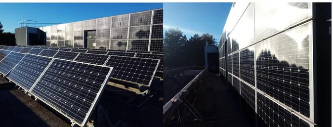
The solar cells used in this building are crystalline silicon cells from the brand TENESOL. Their datasheet is available in ANNEX 1. While panels are used as is on the roof and terrace surfaces (Figure 14), the separate cells are directly integrated inside of double and triple glazing for the façade and window surfaces as seen in Figure 15.
Figure 14: Regular crystalline silicon PV cells installed on the terrace and walls of the ADREAM building
33
Figure 15: Double and triple glazing PV façade of the ADREAM building
Today, ADREAM is entirely monitored through a large sensor network, which includes a meteorological station. The acquisition of multiple years of production and consumption data allows the extensive examination of the building’s functioning, as well as its ongoing optimization. This process relies on a large amount of data (thermal, electrical, air quality, comfort, lighting, etc.) being stored every day in the platform’s database through 6500 sensors. The database is accessible through a supervision tool (Figure 16) as well as a web interface inside of the laboratory. Specific data can be extracted for further studies.
Figure 16: ADREAM's supervision tool, user interface
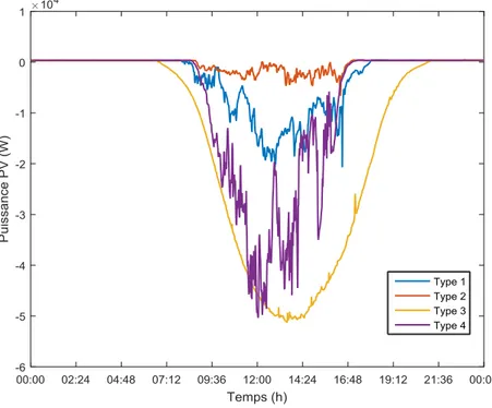
Figure 17, Figure 18 and Figure 19 show the measured data for PV energy production for the years 2014, 2015, and 2016 respectively, with a sampling period of one hour. In addition, the same data sets with a sampling period of one day are represented in ANNEX 2.
34
Figure 17: ADREAM's measured PV Energy Production (2014)
35
Figure 19: ADREAM's measured PV Energy Production (2016)
As it can be seen on these graphs, non-negligible periods of data are missing in the years 2014 and 2016. This is due to a malfunction in the sensor and database systems of the building. These respective periods will therefore be ignored in the simulations and results.
Recent scientific studies on the building are based on the concept of New Generation Energy Networks. The related domains include power electronics, data processing, security functioning, and automation. The resolution of the associated challenges demands the understanding of the different behaviors of connected systems in an electrical network, such as photovoltaic panels and inverters, through complete model elaboration and analysis. Each type of energy source (thermal or electrical) present in the building can be studied through a modular monitoring infrastructure. Additionally, the emulation of different consumption profiles (e.g. lighting, electronic equipment, data servers) coupled to human usages is possible.
Therefore, a modeling approach to energy management and optimization for the totality of the systems, integrating all the entities of production and consumption has been initiated. For this Thesis work, the part of PV production modeling is discussed in the following section.
36
2.3. Modeling PV production
In order to estimate the PV energy production for the building ADREAM, an optimized solar irradiation model was used to estimate the solar radiation on surfaces of different inclinations. This model was developed through Matlab and parts of it are based on previous PhD research [46] and renown models from the literature [47][48][49][50][51]. I participated in the optimization of the models before this PhD during my Master internship in LAAS.
2.3.1. Design of Solar Irradiation Model
Solar irradiation on terrestrial surfaces, as explained in chapter 1, is highly dependent on the composition of the atmosphere. Furthermore, estimating the solar radiation incoming on different surfaces with varying inclinations and properties is a complex matter. This subsection presents a model developed to estimate solar producible on ADREAM’s PV surfaces by using the horizontal global irradiance measure provided by pyranometer of the meteorological station on the building’s roof.
For the development of an optimized solar irradiation model, a good understanding of the composition of solar radiation on a terrestrial surface is necessary. Direct radiation (S), diffuse radiation (D) and reflected radiation (R) add together to form the global radiation (G) on a surface as given in equation (1) and illustrated in Figure 20.
𝐺 = 𝑆 + 𝐷 + 𝑅 ( 1 )
Figure 20: Division of the global radiation (G) into direct (S), diffuse (D) and reflected (R) radiation
For the estimation of the global irradiance on an inclined surface such as a PV panel, it is necessary to estimate each of these components for the given inclination ‘i’ as shown in equation (2).
37 The reflected part can be neglected based on the surrounding environment and the direct part (S, Si) can be determined through geometric calculations. However, the estimation of the The reflected part can be neglected based on the surrounding environment and the direct part (S, Si) can be determined through geometric calculations. However, the estimation of the diffuse component of the global irradiance on a given inclined surface is the determining and more complex part of a solar irradiation model. Many attempts to model D and Di have been carried out in literature. The works of Temps and Coulson [47], and Klutcher [48] study the horizontal diffuse irradiance while Skarveith [49], Orgrill and Hollands [50], and Erbs [51] study the diffuse irradiance on a surface of given inclination. These existing models have been compared and combined into an optimized and calibrated solar irradiation model. The details of the complete model are shown in [52] and Figure 21 shows an overview of its structure.
.
Figure 21: Simplified diagram of the solar irradiation model
As it can be seen in Figure 21, this model uses only one input, which is the global horizontal solar irradiance data for a given period of time.
2.3.2. PV Energy Production
Using this optimized model and global horizontal solar irradiance data from a pyranometer integrated in the ADREAM building, we can estimate the global irradiance on each inclined
38 photovoltaic surface for every minute of the year. This estimated data will be used to calculate the total PV power and total PV energy production of the platform.
Various PV systems are integrated in the ADREAM building. Each system is composed of a specific string of PV panels tilted at a given angle, connected to a single inverter as shown in Section 3.2, Table 1. Using equation (3), the electrical production of each individual PV system can be calculated, as the specific efficiencies of each subsystem are known.
𝑃𝑠𝑦𝑠𝑖 = 𝑃𝑉𝑠𝑢𝑟𝑓𝑎𝑐𝑒𝑖∗ 𝐺𝑖𝛼𝑖∗ 𝜂𝑃𝑉𝑖∗ 𝜂𝐼𝑁𝑉𝑖 ∗ (1 − 𝑀𝑀𝑙𝑜𝑠𝑠) ∗ (1 − 𝑂𝐻𝑀𝑙𝑜𝑠𝑠) ( 3 )
Where:
𝑷𝒔𝒚𝒔𝒊: Electrical power produced by the system ‘i’[W]; 𝑷𝑽𝒔𝒖𝒓𝒇𝒂𝒄𝒆𝒊: Total PV surface in the string ‘i’ [m²];
𝑮𝒊𝜶𝒊: Global inclined irradiance arriving on a surface at angle α [W/m2];
𝜼𝑷𝑽𝒊: Efficiency of the PV panel technology used in string ‘i’; 𝜼𝑰𝑵𝑽𝒊: Efficiency of the inverter connected to string ‘i’;
𝑴𝑴𝒍𝒐𝒔𝒔: Mismatch losses [%]; 𝑶𝑯𝑴𝒍𝒐𝒔𝒔: Ohmic losses [%].
The total PV power (Ppvtotal) in Watt for the whole building is calculated by adding the power of all the PV systems.
𝑃𝑝𝑣𝑡𝑜𝑡𝑎𝑙 = ∑ 𝑃𝑠𝑦𝑠𝑖 𝑖
( 4 )
The final goal of this type of model is to estimate the annual PV energy production in order to study the impact of BIPV in ZEBs as seen in the previous sections. As the input data from the buildings sensors has a period of one minute, the annual energy consumption can be calculated by integrating the total PV power Ppvtotal over the examined time period. The results of the simulation are presented in Figure 22, Figure 23, and Figure 24. In addition, the same simulation result data sets with a sampling period of one day are visible in ANNEX 3.
39
Figure 23:Simulated PV Energy Production with Matlab (ADREAM, 2015)
Figure 24: Simulated PV Energy Production with Matlab (ADREAM, 2016)
A comparison between these simulation results with the measured data on a yearly basis is shown on the graphs in Figure 25, Figure 26 and Figure 27 below.
40
Figure 25: Annual Electrical Energy Production from ADREAM's PV Systems (2014), measured and simulated
Figure 26: Annual Electrical Energy Production from ADREAM's PV Systems (2015), measured and simulated