O
pen
A
rchive
T
oulouse
A
rchive
O
uverte (
OATAO
)
OATAO is an open access repository that collects the work of Toulouse researchers and makes it freely available over the web where possible.
This is an author-deposited version published in: http://oatao.univ-toulouse.fr/
Eprints ID: 5380
To link to this article:
http://dx.doi.org/10.4028/www.scientific.net/KEM.446.83
To cite this version : Garnier, Christian and Mistou, Sebastien and Pantalé, Olivier Influence of Process and Material Parameters on Impact Response in Composite Structure: Methodology Using Design of Experiments. (2010) Key Engineering Materials, vol. 446 . pp. 83-90. ISSN 1013-9826
Any correspondence concerning this service should be sent to the repository administrator: [email protected]
Influence of process and material parameters on impact response in
composite structure: methodology using Design of Experiments
C.Garnier
1,2,a, S.Mistou
1,band O. Pantalé
1,c1
Université de Toulouse, INP/ENIT, LGP, 47 avenue d'Azereix, BP 1629, F-65016 TARBES cedex, France
2
Daher Aerospace, Research & Development Department, 23 route de Tours, BP 17, Saint Julien de Chedon, F-41401 Montrichard Cedex, France
a
[email protected], [email protected], [email protected]
Keywords: impact response, RTM process, LRI process, composite structure, design of
experiments.
Abstract. Even if the mechanical performances of composite materials give new perspectives for
the aircraft and space design, the variability of their behavior, linked to the presence of initial microscopic defects or led in service, constitute however a still important brake in their development. As regards particularly the response to fatigue loads or ageing, the behavior of these materials is affected by several sources of uncertainties, notably on the nature of the physical mechanisms of degradation, which are translated by a strong dispersion in life time.
In aerospace industry, low energy impact phenomenon is not well known concerning composite materials and composite structures. Many manufacturers use important safety factors to design structures. The aim of this work is to define the most predominant parameters which permit a good response of damage using experiences plans. The differences of these parameters by using Resin Transfer Molding (RTM) or Liquid Resin Infusion (LRI) process than prepreg one is also studied in this work.
Introduction
Nowadays, in aerospace industry, composite materials are used but their behavior is not well known. During their life in aerostructure, these materials are subjected to many different loads as maintainability impacts, hail, birds, and others. These loads can be classified according to their energies or strain speed, as shown on figure 1 and 2.
Under dynamics loads or medium loads, the structure is affected and many damages are visible. In this case, this structure is automatically replaced. In case of quasi-static loads, the surface of the structure is few affected but damage can occur in it. The detailed inspection (DET) and General Visual Inspection (GVI) inspection do not reveal systematically these defects.
One of the main problems is to know how the structure responds on impact in terms of damage produced inside and residual strength after impact. The knowledge of the entire phenomenon which acts in this response is a good way to control it. First, we have to define these phenomena and all the parameters linked to them. Then, we have to understand how they act to choose the best configuration. To understand all the effects, we have to make experiments using a special test apparatus. For the low energy impacts, a drop weight machine is used, and for upper energies, a gas gun is used. Furthermore, we decided to know how the sample, impacted or not impacted, behave under fatigue loads. The aim is to understand how the damage will initiate for no impacted samples and how it will propagate for others.
State of the art.
Parameters acting on impact response.
In its final report in 1998, the FAA [1] does a state of the art about parameters which can modify the impact response of composite structures. In its report they classify these parameters in three parts. One part of these reported to the impactor, another one of these reported to the target and a third one for parameters reported to the material and its manufacturing process.
In 1992, Demuts and al. [2] compare 2 resin/epoxy systems: graphite / epoxy and graphite / BMI. They note that using the resin BMI doesn't give any advantage concerning residual strength in compression after impact.
In 1994, Hitchen and al. [3] study the influence of the lay up on carbon/epoxy samples impacted by 7 J. They denote that the layup modifies the shape and the size of the delamination. It also modifies the energy level to initiate delamination. Besides, the layup acts on the structure strength before and after impact.
In 1995, Hinrich and al. [4] work on the impact in composite panels, made by RFI (Resin Film Infused) process, under compression load. They denote that thinner is the sample, higher is the damage area. They also note that the contact force is affected by the shape and the speed of the impactor. The prediction of the contact force shall be done separating the kinetic energy in two energies : elastic energy and Hertz contact energy.
In 1998, Fuoss and al. [5] decide to study the influence of the stacking sequence on the impact resistance of composites laminates varying three parameters: interface angle, ply orientation relative to a fixed axis and ply grouping. Concerning angle interface, they denote that increasing the number of angle interface reduces the damage area. For the ply orientation to a fixed axis, they note that changing the angle influences the impact response. Changing the stacking sequence changes the impact behaviour but each configuration is specific. Modifying specimen geometry or boundary conditions will change the impact response. It is noted that the ply grouping reduces the damage resistance and so, increases the damage area.
In 1998, Ambur and Starnes [6] work on plane and curvative samples. They show that the radius of curvature doesn't act on the contact force but acts on the compression after impact residual strength.
In 1999, Tai and al. [7] work on the influence of the thickness of composite on the response of impact and on its fatigue behaviour. They predict that a linear relation exists between the stress level and the life duration under fatigue load.
In 2002, Cartié et al. [8] study the influence of resin and fiber properties. They use six carbon / epoxy composites: four different resins and two different fibers. Impact tests were done using a drop weight machine with a speed which varies between 1 and 3 m.s-1. They denote that, for CAI tests, resin toughness is the most significant parameter. Changing type of fiber does not alter or few alter compression after impact residual strength. Moreover, the type of resin acts on the level of damage initiation load after impact.
In 2004, Mitrevski and al. [9] want to determine the influence of the impactor shape using three different shapes: flat, hemispheric and conic and two impact energies. They also use two different lay up for carbon/epoxy prepreg samples. They conclude that coarser is the indentation, higher is the absorbed energy by the coupon. The hemispheric impactor increases the peak contact force, decreases the contact duration and creates a smaller indentation.
Currently, many approaches around materials are made. Instead of using only thermosetting resin, two components resins are used: thermosetting one with thermoplastic interleaving or particulate thermoplastic polymer are locally located in the resin [10, 11, 12, 13].
Many parameters act on the response of impact of composite structures. In most of cases, authors use prepreg to make their samples. To confirm that the same parameters act on RTM, as shown on
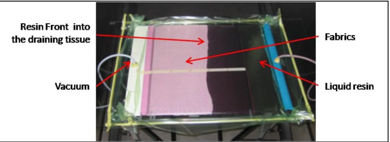
figure 3, or LRI processes, as shown on figure 4, a decision to make a design of experiments with many parameters was done.
Figure 1 : Principle of Resin Transfer Molding
Figure 2 : Sample during Liquid Resin Infusion (LRI) process Fatigue
Many investigations were carried out from fatigue loading on composite structure and their behaviour [14-20]. Most of these investigations show that fatigue behaviour of composite structure is a complex phenomenon. Many factors act on this behaviour, such as the loading level, the frequency, etc. However, few studies take into account the worsening character of compression during fatigue loading. Most of the pre-cited works deal with tension-tension fatigue loading. But, when a fatigue cycle takes into account compression, local or global buckling shall appear [21] and initiate in a premature way damages.
Concerning the damage development, many properties of the materials act on it. The inhomogeneous microstructure and the variable quality of many commercial composite materials [22], where there are small disparate porosities or cavities on it, the stiffness or strength of the composite lead to complex damage development and to different modes of failure like delaminations, disbondings, fibre breakage, etc [23].
About the experimental procedure, Bathias, Behesty and Tai [24, 25, 7] consider that the most penalizing cyclic damage is fatigue under traction/compression. Moreover, they found that the component in compression of a loading in traction/compression must be important to show its effect on the life reduction after impact. Consequently they use a loading ratio of -1 between the minimum and maximum stress.
In their works, Minnestyan, Philippidis and Post [26- 28] make a non exhaustive list of models which predict residual strength. Existing models as Sarkani et al., Broutman and Sahu, Schaff and
Davidson, Hahn and Kim, Rotem, Yang et al.,interaction model, Sendeckyj, modified Broutman and Sahu model, modified Hahn and Kim, modified interaction model and non linear model were compared. Different types of coupons were tested and compared with numerical models. They note that most of them are not completely reliable concerning residual strength after fatigue. Some models correlate well with the experiment curves of life at the beginning while others correlate near fracture. The experimental results show that the dispersion of residual static strength increases with the accumulation of the damage during the increase in the number of endured cycles. Most of the cited models follow this trend.
All the precited models and comparisons of them with experiments were carried out from prepreg Fiber Reinforced Plactics. None of them were compared with RTM-FRP or LRI-FRP.
Testing methodology
In order to do design of experiments, it has been decided to classify the parameters in 3 classes: process, materials and testing parameters. The first class includes the entire parameters which act during the manufacturing of the structure. The temperature of the resin, the temperature of the mold, the room temperature, the pressure, the time of polymerization, the time to reach the temperature of polymerization can be cited. All the data which can change or variable during the manufacturing can be integrated on the design of experiments. The second class involves the nature of the fibre, the tow, the density and the thickness of a ply, the basis weight, the different mechanical and chemical treatment of the fiber, the stacking sequence, the nature of the resin, the number of components of the resin. And for the third class, the weight and the shape of the impactor, the boundary conditions of the sample, the impact energy shall be parameters. The aim of the design of experiments (DoE) is to know the most important parameters acting on the impact response for two different processes: LRI (Liquid Resin Infusion) and RTM (Resin Transfer Molding). Two considerations in the building of the DoE are the fact that some parameters of these processes are different and that the direction of the resin injection is different. So it has been decided to build two DoE: one for LRI process and other one for the RTM one, keeping the same parameters for the materials (tow, basis weight, ...) and for the impact testing ( impactor weight, radius of impactor tap, ...) .
As seen before, many parameters should be used in our Design of Experiments. In order to predict the influence of each parameter, the coupling between them and the curvature of the DoE, it has been decided to reduce the number of factors and so, the number of specimen to produce. Here is the general response of the DoE:
2 0 BiXi BijXiXj BiiXi B
Y (Eq.1)
where Xi is the parameter i, Bi the influence of the parameter Xi, Bij the interaction between Xi and Xj, Bii the curvature of the plan and Y is the response.
First, the way to reduce the high number of parameters for the material class has to be chosen. Nowadays, most of composite aerostructures are made with epoxy resin and carbon fiber. Moreover, only few resins are qualified for aircraft. Deciding to use only epoxy resin seems to be a good choice to reduce the number of parameters. Concerning fibers, we decided to choose carbon.
Secondly, concerning intrinsic fiber parameter, the study shall be done varying parameters which are easy to change. Some parameters shall be changed in concert with suppliers on basis of the existing fibers. Moreover these parameters must be, as far as possible, independent from one to other. So we choose these four parameters: tow, basis weight, type of fiber, type of fabric. One more chosen parameter for the experiments plan is the powdering of the fabric. The aim of this parameter
is to predict the level of joining between the powder and the resin for LRI and RTM process. As we note in [Fuos98], the stacking sequence works on the impact response of composite structure. So it will be added in the design of experiments.
On the implementation of composite materials, we will take as the basic the polimerization cycle of epoxy resin. This cycle is composed of 3 stages: temperature rise, polymerization step and decreasing temperature. For the first one and the third one, the speed will be introduced as parameter. But for the polymerization step, we add time and temperature.
The main difference between the two processes is the pressure. LRI used a vacuum pressure while RTM use pressure. Each one will be a parameter for the concerned process.
For each parameter, a field variation will be chosen using for each one 2 or 3 levels.
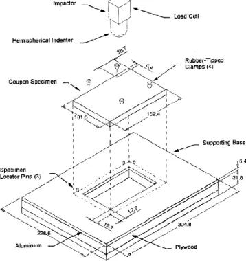
To know how the structure reacts on impact, we have to make experiments. Low energy impact testing will be made on samples. We choose energy which will approximate the Barely Visible Impact Damage (BVID). So we will impact the samples using a drop weight impact tester (fig. 1) able to keep the drop weight after the first impact (brake). According to the AITM 1.0010, the measurements of samples are 100 mm * 150 mm with a thickness of 4 mm. Concerning the impactor, we will use one, made in steel, with hemispheric tap which weight 1 to 3 kg. This testing will take place on new samples and also on old samples, ageing under fatigue loading, impacted or not impacted.
To define the influence of each parameter, we have to measure responses of the experiments plans. We decided to measure the health of the samples before impact, three-dimension geometry of the damage produced by impact, and residual mechanical properties.
Figure 5 : Drop weight test machine
The response of the DoE is a good way to understand low energy impact phenomenon. The 3D geometry and the reduction in mechanical properties will be a help in the design of composite aerostructures. This study will give a safety ratio taking into account the impact phenomenon.
Also, this study is good start to evaluate the mechanical behavior of impacted composite structures under fatigue loading.
Summary
This study concerns composite structures and how they response to a low energy impact. The methodology used is based on a design of experiments (DoE). First, studying done works, a list of parameters acting on impact structure is made. These parameters should be classified on three groups: material, process and testing parameters. Three responses of the DoE are measured: material health, before and after impact loading, geometry of the produced damage and residual mechanical properties. The aim of this study is to understand the low energy impact phenomenon and how it act on impact repose of composite structure.
The second work is to understand the behavior of the structure before and after low energy impact loading under fatigue loads. Different medium are used to follow the damage growth.
References
[1] H.P. Kan, Final report DOT/FAA/AR-97/79 (1998).
[2] E. Demuts, R. S. Sandhu, J.A. Daniels, report N° DOT/FAA/CT-92-25 (1992) 1097 - 1104. [3] S.A. Hitchen and R.M. Kemp, Comp. 26 (1994) 207-214.
[4] GS. Hinrich, V. Chen, D. Jegley, L.C. Dickinson and K. Edward, NASA conference publication 3294 (1995).
[5] E. Fuoss, P.V.Straznicky, C. Poon, Comp. Struc. 41 ( 1998 ) 67 -77.
[6] D.R. Ambur and J.H. Starnes Jr,, In structures, structural dynamics, and material conference (1998).
[7] N.H. Tai, C.C.M. Ma, J.M. Lin and G.Y. Wu, Comp. Sci. and Tech.59 (1999) 1753-1762. [4] GS. Hinrich, V. Chen, D. Jegley, L.C. Dickinson and K. Edward, NASA conference publication 3294 (1995).
[8] D.D.R. Cartié, P.E. Irving, Comp. part A 33 (2002) 483 - 493.
[9] T. Mitrevski, I.H. Marshal, R. Thomson, R. Jones and B. Whittingham,, comp. struct. (2004). [10] G. Caprino, P. Iaccarino and A. Lamboglia, Composite structures 88 (2009) 360-366.
[11] A. Duarte, I. Herszberg and R. Patton, Composite structures 47 (1999) 753-758. [12] J. Masters, Key Eng. Mater. 37 (1989) 317-348.
[13] H. Kishi, M. Kuwata, S. Matsuda, T. Asami and A. Murakami, Composites Science and technology 64 (2004) 2517-2523.
[14] Reifsnider, KL, Lesko J, Case S. IUTAM - Symposium on Mechanics of Composite Material (1983); 399-420.
[15] Talreja R, Yalvac S, Yats LD, Wetters DG. Transeverse cracking and stiffness reduction in cross-ply laminates of different matrix toughness. J of comp mat 1992; - 26(11): 1644-1663. [16] Gathercole N, Reiter H, Adam T, Harris B. Life prediction for fatigue of T800/5245
[17] Mao H, Mahadevan S. Fatigue damage modelling of composite materials. Comp Struct 2002; 58:405–410.
[18] Dzenis YA. Cycle-based analysis of damage and failure in advanced composites under fatigue: 1. Experimental observation of damage development within loading cycles. Int J of Fatigue 2003;25(6):499-510.
[19] Gros XE, Bousigue J, Takahashi K. NDT data fusion at pixel level. NDT & E Int 1999;32(5):283-292.
[20] Vary A. Acousto-Ultrasonics, In: Nondestructive testing of fiber reinforced plastics. Composites 1990;2:1-54.
[21] Lachaud F., thèse de doctorat, Université Paul Sabatier Toulouse (1997)
[22] Smith T.R. and Owen M.J, proceedings of the sixth International reinforced plastics Congress (1968).
[23] B. Harris, Fatigue in Composites (2003).
[24] C. Bathias, Eng. Fract. Mech. 40 (1991) 757 -783.
[25] M.H. Behesty and B. Harris, In : ICFC 1 (1997) 365-372.
[26] L. Minnetyan, Computational simulation of composite structural fatigue, report NASA/CR_2005-213573 ( 2005).
[27] T.P. Philippidis and V.A. Passipoularidis, Int. J. Fat. 29 (2007) 2104-2116. [28] N.L. Post, S.W. Case, J.J. Lesko, Int. J. Fatigue ( 2008 ) 2064 - 2086.