O
pen
A
rchive
T
oulouse
A
rchive
O
uverte (
OATAO
)
OATAO is an open access repository that collects the work of Toulouse researchers
and makes it freely available over the web where possible.
This is an author -deposited version published in:
http://oatao.univ-toulouse.fr/
Eprints ID: 2236
To link to this article: DOI: 10.1109/SURV.2010.021110.00086
URL:
http://dx.doi.org/10.1109/SURV.2010.021110.00086
To cite this version: SOMMER Jörg, GUNREBEN Sebastian, MIFDAOUI Ahlem,
FELLER Frank, KOHN Martin, SAB Detlef, SCHARF Joachim. Ethernet - a survey on
its fields of application. IEEE communications surveys and tutorials, 2010, vol 12 (n° 2).
pp. 263-284.
ISSN 1553-877X.
Any correspondence concerning this service should be sent to the repository administrator:
[email protected]
Ethernet – A Survey on its Fields of Application
J¨org Sommer, Sebastian Gunreben, Frank Feller, Martin K¨ohn, Detlef Saß, Joachim Scharf
University of Stuttgart, Institute of Communication Networks and Computer Engineering
Pfaffenwaldring 47, 70569 Stuttgart, Germany
Email: [email protected]
Ahlem Mifdaoui
Toulouse University, ISAE
1 place Emile Blouin, 31056 Toulouse, France
Email: [email protected]
Abstract— During the last decades, Ethernet progressively became the most widely used local area networking (LAN) technology. Apart from LAN installations, Ethernet became also attractive for many other fields of application, ranging from industry to avionics, telecommunication, and multimedia. The expanded application of this technology is mainly due to its significant assets like reduced cost, backward-compatibility, flexibility, and expandability. However, this new trend raises some problems concerning the services of the protocol and the requirements for each application. Therefore, specific adaptations prove essential to integrate this communication technology in each field of application.
Our primary objective is to show how Ethernet has been enhanced to comply with the specific requirements of several application fields, particularly in transport, embedded and mul-timedia contexts. The paper first describes the common Ethernet LAN technology and highlights its main features. It reviews the most important specific Ethernet versions with respect to each application field’s requirements. Finally, we compare these different fields of application and we particularly focus on the fundamental concepts and the quality of service capabilities of each proposal.
I. INTRODUCTION
In 1972, Robert Metcalfe and his colleagues at the Xerox Palo Alto Research Center developed a local area network (LAN) technology to interconnect stations, servers, and pe-ripheral devices within the same building using a common bus system [1]. This was the birth of the first version of Ethernet. They improved the throughput of the installed Aloha network [2] by a collision detection algorithm [3] and filed the corresponding patent in 1977 [4]. This was the creation of Ethernet’s media access control protocol carrier sense multiple access with collision detection (CSMA/CD, [5]).
Together with Intel and DEC, Xerox first published a mod-ified Ethernet version in 1980, which became the well-known DIX Ethernet II version. The first products were available in the early 1980s. In 1985, the IEEE began to standardize the different versions of Ethernet. They avoided the brand name Ethernet and named the technology 802.3 CSMA/CD [1] instead.
Until the mid 1990-ies, several other LAN technologies co-existed with Ethernet, including token ring [6], fiber dis-tributed data interface (FDDI, ANSI X3T9.5), and attached resource computer network (ARCnet, ANSI/ATA 878.1-1999). However, Ethernet succeeded in becoming the dominant LAN
technology for companies as it quickly adapted to upcoming requirements.
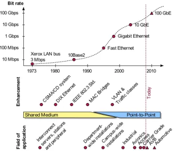
The main requirements of a LAN technology for a com-pany are planning reliability, future proof hardware, and easy management (i. e. plug-and-play capabilities). This especially includes scalability with respect to network size and link speed as well as simple migration. Consequently, the fast band-width evolution in the mid/late 1990-ies while maintaining backward-compatibility laid the fundamentals of Ethernet’s success story. Since its invention, Ethernet’s line rate has evolved from 2.94 Mbps to higher rates: 10 Mbps in the early 1980s (DIX Ethernet II), 100 Mbps in 1995 (IEEE 802.3u), 1 Gbps in 1998 (IEEE 802.3z, [5]), and 10 Gbps in 2002 (IEEE 802.3ae). Currently, the IEEE P802.3ba task force is working on 40 Gbps and 100 Gbps [7]. Figure 1 depicts this bandwidth growth.
In addition to installations limited to single departments of large companies, Ethernet became attractive for campus-wide deployments as well as for small companies/offices (SOHO). With an increasing penetration of permanent broadband Inter-net access, the same applies to residential users. EtherInter-net’s easy adaptability enabled this success in a wide range of surroundings. For residential users, Ethernet offers plug-n-play operation, requiring hardly any manual configuration. In corporate networks, Ethernet enables highly sophisticated networking as described in the next section. Similarly, Ethernet devices range in their complexity and functionality from simple, widely available mass-market products without much functionality (apart from frame forwarding) to specialized, high-performance and feature-rich devices.
Besides wired interconnection, Ethernet also supports the interconnection of wireless technologies, e. g. IEEE 802.11 compliant WiFi [8]. Ethernet seamlessly integrates wired and wireless technologies, since they show both the same logical link layer interface.
This flexibility of Ethernet is its key to success in the enterprise and SOHO networks. Furthermore, thanks to its low cost, long lifetime, and easy integration with other network technologies, Ethernet has become an attractive option in other areas, too. Ethernet’s promise of being inexpensive, both in terms of mass-market equipment and simple operation, and its predominance in customer LANs make it interesting for transport network operators. Therefore, Ethernet is an
This work has been submitted to the IEEE for possible publication. Copyright may be transferred
without notice, after which this version may no longer be accessible.
10 Gbps 100 Gbps 100 Mbps 10 Mbps 1973 1980 1990 2000 2010 Bit rate 1 Gbps
Xerox LAN bus 3 Mbps 10Base2 Fast Ethernet Gigabit Ethernet 100 GbE 10 GbE CSM A/CD syste m IEEE 802.3 Std. DIX Ethe rnet MAC Brid ges VLAN & Traff ic cla sses
Shared Medium Point-to-Point
F ie ld o f ap p lic at io n Indus trial AVB Avion ics Acce ss Carri er G rade Autom otive Inter conn ect serv ers, statio ns and p eriph eral Depa rtmen t-wide insta llatio ns Cam pu s-wide instal lation s T od ay E n h an ce m en t
Fig. 1. Ethernet’s story of success, its enhancements, and its fields of application
attractive replacement for metro and core network technologies as well as an access technology.
While manufacturing companies interconnect their offices using Ethernet, inter-machine communication uses fieldbuses. Convergence of both networks requires a common communi-cation infrastructure such as Ethernet in the industrial field. The environments of maritime and railway applications are similar to the industrial environment. We consider them as special cases of industrial Ethernet.
Lightweight devices, mass-market products, and high band-width communication enabled the success of Ethernet in aircraft. In addition, multimedia devices need interconnection in various areas of our life. The technology discussed to interconnect these devices at home or inside a vehicle is Ethernet.
We classify these fields of application of Ethernet according to their characteristics and requirements as depicted in figure 2. Ethernet started as a local network technology in corporate networks and SOHO. From there it evolved towards public and private networks. The public networks include operator networks (carrier grade Ethernet) and Ethernet in the first mile. Private networks include embedded networks (industrial, avionic, automotive) as well as the multimedia networks. Since private organizations manage these networks, they show
sealed-off characteristics. The home multimedia networks
actually fall in-between LANs and embedded networks. They show almost all characteristics of the original Ethernet LAN, but are also close to embedded networks as they are privately administrated.
In this paper, we introduce Ethernet in different fields of application and show its according evolution. We first give an introduction to the common Ethernet LAN technology, used and formed primarily in corporate networks, and highlight the drivers of this technology in section II. This is the basis for the extended Ethernet versions.
We show the modified versions of Ethernet for transport
Home Multimedia Networks ▪ AVB
Local Area Networks ▪ Corporate LAN ▪ SOHO Transport Networks ▪ Carrier Grade ▪ Ethernet in the First Mile
Embedded Networks ▪ Industrial ▪ Avionics ▪ Automotive
Fig. 2. Classification of Ethernet’s fields of application
networks, namely metro and core networks, and Ethernet in the first mile in sections III and IV, respectively. We address Ethernet in embedded environments with safety and time-critical applications like machine control, aircraft, and in-vehicle communication in sections V, VI, and VII, respec-tively. A further application field of Ethernet, currently in the standardization process, is the audio and video domain described in section VIII. In each of these sections, we introduce the constraints and requirements of the respective field of application. In section IX, we compare and contrast these different versions of Ethernet with respect to common characteristics and major differences. We conclude this paper in section X.
II. ETHERNETLAN TECHNOLOGY
This section introduces Ethernet LAN technology and its main features. The main driver for Ethernet is its easy ap-plication in corporate and residential networks. Some of the features of Ethernet are directly coupled with the needs in corporate networks. Figure 1 shows the Ethernet features and their time of invention.
We first introduce the corresponding standards and the protocol stack of Ethernet. In a bottom up approach, we then introduce the physical layer and the MAC framing layer and focus on the Ethernet features on each layer. The Ethernet bridging functionality and its concepts for routing and for-warding of frames close this section.
A. The IEEE 802 family
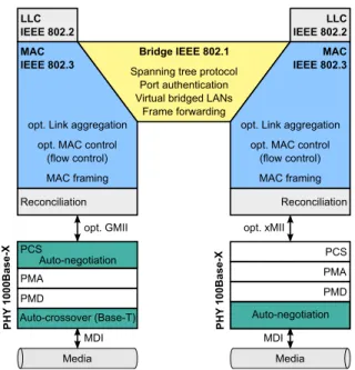
Figure 3 classifies the Ethernet protocol stack with respect to the lower layers of the ISO/OSI reference model. IEEE 802.3 Ethernet splits the functionality of the data link layer (DLL) in three different parts: the logical link control (LLC, IEEE 802.2, [9]), the bridge layer (IEEE 802.1, [10]), and the media access control layer (MAC, IEEE 802.3, [5]). IEEE 802.3 also specifies the physical layer of the ISO/OSI reference model, PHY in Ethernet. Ethernet PHY offers a media independent interface (xMII) to the MAC layer and a media dependent interface (MDI) to the physical media. Between these layers, the physical coding (PCS), the physical medium attachment (PMA), and physical medium dependent (PMD) layers reside. For the detailed functionality of each of these layers we refer to IEEE 802.2 [9] and [1] as they are out of scope of this paper.
Fig. 3. Ethernet protocol stack including its functions
B. Physical Layer
This section introduces the available physical media of Ethernet, provides a short review on the evolution of the line rates, and auto-X features of the physical layer. IEEE 802.3 [5] serves as a reference for the different media.
1) Media and Line Rates: In the early days, Ethernet
technology offered a line rate of 10 Mbps using a common bus applying coaxial cabling. This setup was the standard for a long time in the LAN. Besides coaxial cabling, IEEE 10Base-F also enabled an optical transmission.
Ethernet evolved towards higher speeds of 100 Mbps (Fast Ethernet) using twisted pair cabling or fiber. IEEE 100Base-TX/T4 refers to shielded and unshielded twisted pair cabling with a maximum range of about 100 m using category 4 or 5 cables. Besides copper, the IEEE also specified single-mode and multi-mode fiber usage. This extended the range towards several kilometers.
The next evolution step was 1 Gbps (Gigabit Ethernet). The corresponding technologies are 1000Base-LX/SX defining long-range and short-range types of single and multi-mode fibers each using a dedicated wavelength. Besides the optical media, Gigabit Ethernet also supports copper cables. For the later 10 Gbps (10 Gigabit Ethernet) the same media types are available, even on copper basis as defined by 10GBase-CX4. While Gigabit Ethernet still allows half-duplex mode and CSMA/CD, 10 Gigabit Ethernet operates in full duplex mode only. An IEEE working group currently specifies Ethernet with 40 Gbps and 100 Gbps line rate in IEEE 802.3ba [7].
2) Auto-negotiation: Ethernet devices up to Gigabit
Ethernet are backward compatible, supporting down to 10 Mbps. Two interconnected devices of different line rates agree on a common line rate. The auto-negotiation feature of the Ethernet PHY provides this functionality. It resides in the lower part of the PHY if copper cabling is used (on the right in figure 3). For optical attachment units, the functionality resides within the physical coding sub layer (on the left in figure 3).
The auto-negotiation process modulates link pulses ex-changed on idle Ethernet links with line rate information. Upon reception of the pulses, both devices determine the common line rate and duplex mode.
3) Auto-crossover: Connecting two Ethernet devices back-to-back required a special crossover cable for copper 10Base-T and 100Base-10Base-T Ethernet for correct pin coupling. With 1000Base-T, the IEEE proposed the additional feature of auto-crossoverto eliminate the need of these special cables [5].
A transceiver-chip internal crossover within the PHY device enables the auto-crossover function. The auto-configuration
of the media dependent interface (MDI/MDI-X1) enables
this functionality if the device supports it. If none of the interconnected devices supports auto-crossover, coupling with crossover cables is necessary.
C. MAC Framing
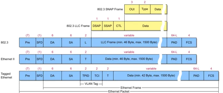
This section gives an overview on the most common Ethernet frame formats defined in IEEE 802.3. In addition, we highlight the Ethernet frame extension for virtual LANs of IEEE 802.1Q. Figure 4 depicts these various frame formats. We start describing common fields using the Ethernet II frame format.
The preamble (Pre) serves for synchronization between sender and receiver using an alternating bit sequence. After the preamble, the start of frame delimiter (SFD) indicates the start of the frame. The destination (DA) as well as the source address (SA) are 6 byte globally unique addresses administered by the IEEE or locally unique addresses assigned by the local network administrator. Besides unicast addresses, Ethernet defines broadcast and multicast addresses [5]. The data field contains the payload of the frame. It has a minimum size of 46 byte required for collision detection by CSMA/CD. In case of less payload, the MAC driver adds padding data. The last field, the frame check sequence (FCS), also called cyclic redundancy check (CRC), contains 4 byte for error detection. The 2 byte following the source address differentiate various Ethernet versions. We discuss them in the next two sections.
1) Frame Formats: The meaning of the 2 byte type/length
field (T resp. L) is context dependent. It either identifies the type of the payload protocol data unit or the size of the MAC frame.
In Ethernet II, T defines the type of the protocol in the payload field. The Ethernet PHY determines the end of a frame on the wire and provides this information to the MAC layer. As the payload PDU indicates the data length anyhow, it is not necessary to provide the length of the MAC frame in the MAC frame itself.
In contrast, the IEEE promotes the encapsulation of the payload PDU in a MAC-layer independent LLC frame. It thereby guarantees the interworking of different underlying LAN technologies. In this case, the MAC frame provides information on the length of the LLC frame (field L in the 802.3 frame of figure 4). The service, i. e. the applied protocol, is then determined by the destination service access point (DSAP) and the source service access point (SSAP) in the
Fig. 4. Ethernet IEEE 802.3 frame formats
LLC frame. The 1 byte control field (CTL) completes this information [9].
As there are only 256 possible SAP values available and the number of protocols in use is much higher, the IEEE defined special values for both DSAP and SSAP. They use the value of 0xAA for DSAP/SSAP and 0x03 for the control field to indicate additional layers after the LLC header. This subnetwork access point (SNAP) indicates the vendor with a 3 byte organizational unique identifier (OUI) and a 2 byte payload type field (TYPE). For compatibility reasons, today’s devices distinguish both cases by the value of the type/length field [11]:
• a value of less than 0x0600 (153610) indicates the LLC
frame size.
• larger values indicate the network protocol type, e. g.
0x0800 for the Internet protocol (IP).
As an example, an Ethernet frame carrying an IP packet looks different depending on the Ethernet version. Ethernet II indicates 0x0800 in the T field, in IEEE 802.3 the SAP values are either 0x06 for IP or 0xAA indicating a SNAP header of type 0x0800.
For completeness, we also mention the Novell Ethernet version for the transport of Novell’s IPX [12]. It interprets the type field as a length field followed by Novell’s IPX protocol without a LLC header. As the first byte of the IPX protocol (0xFF) is different from all possible values of the DSAP field, a distinction of such Ethernet frames on the same LAN segment is possible. Besides this raw encapsulation, Ethernet can also transport IPX packets in an LLC frame or a special SNAP frame [5], [9].
The most dominant Ethernet version in today’s LANs is Ethernet II, with the type/length field indicating the payload type.
2) Virtual LAN Extension: For traffic engineering purposes and security reasons, the IEEE extended the Ethernet frame in IEEE 802.1Q [13] in 1998. The extension enables a virtual separation of multiple LANs on the same physical
infras-tructure. The last row of Figure 4 shows this frame format extension.
The extension consists of an additional 4 byte field inserted in front of the Ethernet type field. Its first 2 byte indicate the tag protocol identifier (TPID), while the second 2 byte represent the tag control information (TCI) field. The TPID corresponds to the type/length field in Ethernet II and its value of 0x8100 identifies an IEEE 802.1Q frame. The TCI field contains a VLAN identifier (12 bit), priority information (3 bit) and one bit canonical format indicator. The VLAN identifier indicates the VLAN the frame belongs to. The priority infor-mation indicates the user priority class. IEEE 802.1Q defines eight different priority classes considered at the schedulers of interworking units. This header extension allows an increased overall Ethernet frame size of 1522 byte.
For further reading we refer to [14] and [15] for an in-depth discussion of this concept.
D. Optional MAC Layers
The IEEE standard allows optional features in the MAC layer above the MAC framing functionality (cf. figure 3, [5]). This includes the MAC control and the link aggregation functions. One representative of the MAC control is the flow control function. In the next subsections, we address this feature and the link aggregation function.
1) Flow Control: IEEE 802.3 defines the special value
0x8808 for the type field (TYPE) to indicate MAC control frames. Within the MAC control frame an opcode distin-guishes different operations. One operation is the Ethernet flow control.
Ethernet flow control is only available between directly connected devices. It enables an overloaded device to ask the neighboring device to interrupt sending before it has to drop frames. The Ethernet device sends an Ethernet control frame to the neighbor station using a globally assigned multicast address2and the opcode for the MAC control pause operation.
The frame body indicates the time to wait prior to resuming to send frames. This option is only applicable in full duplex mode and when both devices are capable of receiving these pause frames. This is determined during the auto-negotiation phase.
As this feedback mechanism may interfere with higher layer protocols’ feedback mechanisms, e. g. the congestion control of the transmission control protocol (TCP), Ethernet flow control is mostly switched off in managed corporate networks. Feuser and Wenzel studied this topic in [16] and quantified the impact on higher protocol layers’ feedback mechanisms.
2) Link Aggregation: Ethernet link aggregation is another optional feature for full duplex capable Ethernet devices (IEEE 802.3, [5], sec. 43). It introduces an additional abstraction layer between the logical link control layer and the optional MAC control layer (cf. figure 3).
Link aggregation provides a single logical interface to parallel physical links between two devices. This increases the link availability and enables a linear increase in the bandwidth. Network administration may configure link aggregation man-ually or apply the link aggregation control protocol (LACP, IEEE 802.3ad) for automatic discovery of parallel links.
Usage of parallel links may cause out of sequence arrivals. In general, higher layer protocols, e. g. TCP, suffer from out-of-sequence arrivals. Therefore, the link aggregation mecha-nism should avoid this, but the standard does not propose any mechanism. Hash functions on the source/destination pairs are common methods to ensure this.
For further reading, we refer to Watanabe et al. They show in [17] the benefits and cost savings using Ethernet link aggregation in a computer cluster.
E. Bridging Layer
This section discusses the functions of the IEEE 802.1 Ethernet bridging layer. Thereby, we focus on the inter-working aspect of Ethernet. We first introduce the available Ethernet network elements and common topologies. Frame forwarding and the spanning tree protocol discussed next are elementary principles in an Ethernet LAN. The port authenti-cation concept closes this section.
1) Network Elements: Attenuation limits the spatial exten-sion of an Ethernet LAN segment. For each medium, the stan-dard defines the corresponding maximum spatial extension. In former days, repeaters3 were used to interconnect segments up to the maximum extension of a collision domain. Today, transparent bridges realize LAN segment interconnects. They interwork on MAC layer and limit the collision domains to single segments. Switch4 products realize this functionality
today.
During the last decades, the number of stations in a LAN increased. As an increasing number of stations reduces the net-work throughput due to collisions, the LAN topology changed. Today, bridges connect stations directly using twisted pair or fiber cabling forming a physical star topology. They operate in full duplex mode avoiding collisions and do not apply
3hubs are multi-port repeaters 4switches are multi-port bridges
CSMA/CD. Interconnected bridges form a mesh topology. Hence, Ethernet evolved from a bus topology to a so-called micro-segmented network with full-duplex links between sta-tions and bridges.
2) Frame Forwarding: The main task of the bridges is
frame forwarding. Thereby, the destination MAC address
determines the forwarding decision, i. e. the outgoing port. A MAC address learning algorithm enables the mapping of destination MAC address and corresponding port [10], [1]. This section introduces both the bridge learning algorithm and the switch architectures deployed today.
On each received frame, bridges perform the following learning algorithm. They store the source MAC address to-gether with the receiving port identifier in a forwarding database (FDB). In addition, they maintain a timestamp for each entry to adapt to network changes. The forwarding decision of a frame bases on the FDB look-up for the DA. If the DA is already in the FDB, bridges forward the frame to the corresponding port. If the database look-up fails, bridges forward the frame to all ports except the receiving one, i. e. they flood it through the network.
Today’s bridges may follow one of two widely deployed forwarding principles: store-and-forward or cut-through. The store-and-forward technique receives the frame completely and forwards it after frame processing. Therefore, it is able to check frame integrity and to apply functions on the encapsu-lated protocols. The cut-through technique forwards the frame as soon as possible after the reception of parts of the Ethernet header. Thus, it is in general not able to check frame integrity. The cut-through technique shows a smaller forwarding latency than the store-and-forward technique. As neither tech-nique is able to guarantee any bounded latency, only relative timing guarantees are feasible using priorization. Today’s devices mostly implement the store-and-forwards techniques as the benefit of the cut-through technique compared to its complexity is negligible [15].
3) Spanning Tree Protocol: As today’s Ethernet networks
have meshed topologies, loops may occur, which may cause infinite cycling of frames. As native Ethernet is not capable of avoiding loops, Radia Perlman developed the spanning tree protocol (STP, [10]) to solve this problem. It forms a minimum spanning tree on a given topology by blocking selected bridge ports. By assigning weights to links and priorities to bridges, a network administrator is able to define an arbitrary spanning tree on an Ethernet mesh topology, e. g. to satisfy load-balancing requirements.
The original spanning tree protocol shows slow convergence in tens of seconds. The rapid spanning tree protocol (RSTP) improved the convergence time to below one second [10]. The multiple spanning tree (MSTP) bases on the RSTP and pro-vides several instances of the RSTP within VLAN enhanced networks [13]. Today’s Ethernet networks mostly apply RSTP and MSTP.
For further reading, we refer to Olifer et al. They discuss in [18] the spanning tree protocol as one of the advanced features in LANs.
4) Port Authentication: In native Ethernet, bridges allow adding of new stations to free ports. These new stations
immediately have access to the network resources. In some environments, especially corporate networks, adding of unau-thorized stations is not desired. In 802.1X [19], the IEEE defines the concept of port authentication serving this purpose. A bridge applying port authentication only forwards frames of authenticated stations. First, a new station (supplicant) has to send an authentication message to the bridge (authenticator) using the extensible authentication protocol (EAP, [20]) encap-sulated in Ethernet frames (EAP over LANs, EPOL). A value of 0x888E in the type/length field of Ethernet characterizes an
EPOL message to the predefined EPOL group address5. The
bridge forwards this authentication message to a centralized authentication server. After successful authentication, the sta-tion is able to participate in the LAN, otherwise its frames are blocked.
As security issues are of major concern in today’s corporate networks, several authors address this topic and provide in-depth information and tutorials on how to make LANs secure. We refer to two books, [21] and [22] for further reading.
III. CARRIERGRADEETHERNET
Ethernet’s promise of being inexpensive, both in terms of mass-market equipment and in terms of simple operation, is attractive to transport network operators. As the metro area is often considered as the initial deployment target of Ethernet in such networks, the term metro Ethernet is used synonymously for carrier Ethernet or carrier grade Ethernet.
There are two basic approaches to introduce Ethernet into carrier networks. On the one hand, Ethernet services de-scribe an Ethernet based interface to corporate customers who purchase connectivity between different sites as a transport service. Since the vast majority of corporate LANs rely on Ethernet, the Ethernet interface renders protocol conversion unnecessary. In addition, it enables bandwidth allocation in finer granularities than traditional transport services and changes of this bandwidth are feasible without replacement of the interface hardware.
On the other hand, Ethernet transport stands for a class of new packet-oriented transport technologies intended to replace traditional transport networks like synchronous digital hierarchy / synchronous optical networks (SDH/SONET). This class of Ethernet transport technologies is manifold. Some technologies adapt Ethernet to their needs, others are not related to it at all. Nevertheless, the latter group is also considered to belong to Ethernet transport as it enables Ethernet services. Two prominent representatives of this group are based on multi-protocol label switching (MPLS, [23]), which is a supplement to IP introducing connection-oriented operation: transport MPLS (T-MPLS, [24]), an MPLS subset standardized by the ITU-T, and the upcoming MPLS transport profile (MPLS-TP, [25]), currently being jointly defined by the IETF and the ITU-T.
The approaches which actually adapt the Ethernet LAN technology mainly add header fields, but may also break with some of the most fundamental principles of Ethernet LANs like connectionless operation. Our description of Ethernet
5EPOL group address: 01-80-C2-00-00-03
transport focuses on the most prominent of the Ethernet-based approaches.
A. Ethernet Services
Ethernet services describe the transparent transport of Ethernet frames through operator networks. The Metro Ethernet Forum (MEF), an industry alliance founded in 2001 promoting the deployment of carrier Ethernet, proposes spec-ifications of such services from the customer’s perspective. Service descriptions according to MEF 6.1 [26] differentiate between port-based Ethernet (E) services and Ethernet virtual (EV) services. The latter support service multiplexing based on different VLAN tags. Proposed service topologies include point-to-point E-Line (resp. EV-Line) services, multipoint-to-multipoint E-LAN (resp. EV-LAN) services, and E-Tree (resp. EV-Tree) services. The latter allow bi-directional communica-tion between one central instance and a number of subsidiaries. Service attributes defined in MEF 10.1 [27] provide a more detailed specification of these services. Inspired by asyn-chronous transfer mode (ATM) service descriptions, they base on bandwidth profiles indicating four parameters: committed information rate (CIR), committed burst size (CBS), excess information rate (EIR) and excess burst size (EBS). Traffic conform to CIR and CBS receives guaranteed service; traffic exceeding CIR and CBS but conform to EIR and EBS is forwarded in a best effort fashion. Complementary to the MEF activities, the ITU-T study group 15 specifies Ethernet services from the operator’s perspective, focusing on point-to-point services in G.8011 [28], G.8011.1 [29], and G.8011.2 [30].
A wide range of transport technologies are able to support Ethernet services, from traditional, circuit-switched technolo-gies like SDH [31]–[33] and optical transport networks (OTN) [34], [35] to more recent packet-switched technologies like MPLS and Ethernet transport.
B. Ethernet Transport
Transport networks face a number of requirements that differ from those of a LAN. Scalability is essential since transport networks cover large spatial extensions and a huge number of attached devices, implying a large address space. Flooding is particularly problematic in large networks, since replicated frames may travel long distances to be finally discarded, thereby wasting transmission capacity. Another set of requirements is due to the quality of service (QoS) properties a transport network operator has to guarantee to its corporate customers. Such properties, defined in a service level agreement (SLA), include bandwidth, availability, as well as delay and jitter. Mechanisms assuring compliance with SLAs are essential as contract penalties may become very expensive. Any new transport network technology has to keep up with the standards set by SDH/SONET, the traditional, widely de-ployed technology. The benchmark for availability is 99.999 % or above with the notorious upper bound of 50 ms for the restoration time in case of a failure. This implies protection or fast restoration mechanisms, along with operations, ad-ministration, and maintenance (OAM) features allowing the
B-DA B-SA B-VID I-SID DA SA S-VID C-VID ET Payload
DA SA S-VID C-VID ET Payload FCS DA SA VID ET Payload FCS
DA SA ET Payload FCS 802.3 Ethernet frame
802.1Q VLAN tagging
802.1ad Provider Bridging
802.1ah Provider Backbone Bridging DA B-DA SA B-SA ET FCS VID S-VID C-VID B-VID I-SID Destination Adress Backbone DA Source Adress Backbone SA EtherType
Frame Check Sequence Virtual LAN Identifier Service VID Customer VID Backbonde VID
Backbone Service Instance Identifier
802.1Qay Provider Backbone Bridging with Traffic Engineering Switching Label
FCS
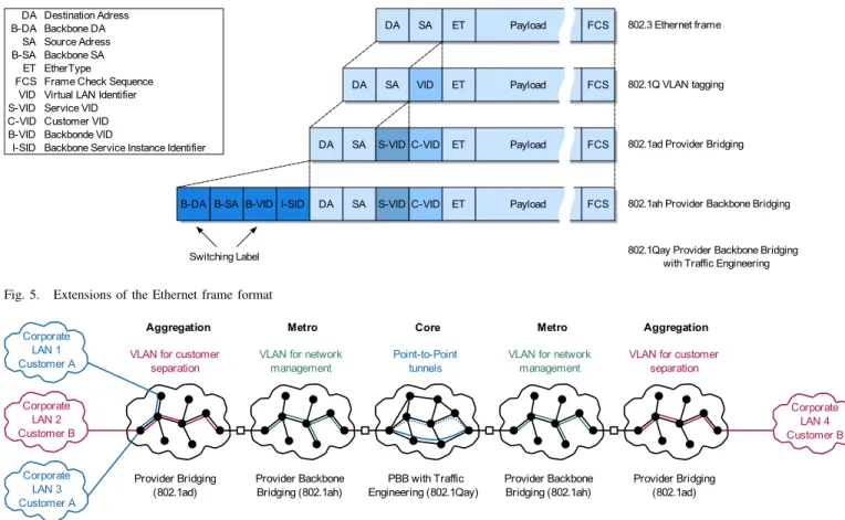
Fig. 5. Extensions of the Ethernet frame format
VLAN for customer separation Provider Bridging (802.1ad) Provider Backbone Bridging (802.1ah) PBB with Traffic Engineering (802.1Qay) Provider Backbone Bridging (802.1ah) Provider Bridging (802.1ad) VLAN for network
management
Point-to-Point tunnels
VLAN for network management
VLAN for customer separation
Aggregation Metro Core Metro Aggregation
Corporate LAN 4 Customer B Corporate LAN 1 Customer A Corporate LAN 2 Customer B Corporate LAN 3 Customer A
Fig. 6. Exemplary deployment scenario of Ethernet transport technologies
detection and localization of failures, as well as performance monitoring. A mechanism mapping frames to the respective customer, i. e. traffic separation, is required to deliver frames to the right interface. In addition, it facilitates SLA compliance by enabling the monitoring of QoS parameters on a per customer basis.
1) Frame Format and Operation: Basic principles of
Ethernet, such as STP and address learning, enable simple set-up and operation of LANs, but are inappropriate to fulfill the requirements stated above [36]. In order to meet those carrier requirements, the IEEE defined an adaptation of Ethernet in a series of amendments to the 802.1 standard. The extensions comprise additional header fields depicted in figure 5 as well as changes of the operational principles.
Traffic separation is achieved in local Ethernet networks by means of virtual LANs, a tagging mechanism. However, the according IEEE standard 802.1Q only permits one tag in a frame (cf. figure 5), preventing a carrier from adding a VLAN tag for customer separation when the customers already use VLANs in their networks. Therefore, the provider bridging (PB) extension IEEE 802.1ad [37] allows the stacking of VLAN tags (VID), i. e. the introduction of a second, so-called service VLAN tag (S-VID) in addition to the customer VLAN tag (C-VID). Carriers can thus define VLANs within their transport networks independently of customer VLAN assignment. Due to the position of the service VLAN field in the Ethernet header, 802.1Q-compliant bridges can perform switching inside a PB network.
In large networks, there are issues with Ethernet’s flat addressing scheme, which PB does not resolve. Bridges in the carrier network would have to maintain a huge number of entries for end devices in their forwarding databases. In practice, this means frequent updating of table entries and sub-sequent flooding to newly unknown destinations. In addition, PB’s service VLAN tags allow for distinction of at most 4094 customers, severely limiting the supportable customer base. The provider backbone bridging (PBB) extension 802.1ah [38], approved in June 2008, addresses both issues by ex-tending an Ethernet frame with a so-called backbone Ethernet header. Figure 5 shows such an external header, which contains backbone MAC addresses assigned to edge nodes of the PBB network, indicating the ingress point and egress point of the frame in the PBB network. Consequently, only the backbone addresses are visible inside the carrier network, resolving the scalability problem related to the flat addressing scheme. A 24 bit service identifier (I-SID) introduced in addition to the backbone VLAN tag allows the differentiation of a larger number of customers. As for PB, standard VLAN capable bridges are able to operate on PBB headers.
The Ethernet control plane remained unchanged from the LAN up to PBB. It is based on the spanning tree protocol (STP), flooding of frames to unknown destinations, and MAC address learning. However, these mechanisms are incompatible with scalability, reliability, manageability, and QoS require-ments of transport networks. First, by deactivating physical links, the STP wastes valuable resources, prevents load
balanc-ing, and artificially prolongs transmission paths. In addition, the only response to failures of active links or a node is the reconfiguration of the spanning tree. Even the improved STP versions, namely RSTP and MSTP, are thereby unable to meet the target restoration time. Second, flooding does not scale with network size. Finally, STP and MAC address learning along with the connectionless forwarding principle leave little room for carriers to control the operation of their networks. In particular, they prevent traffic engineering desirable for improved network utilization, better QoS capabilities, and fine-grained protection switching mechanisms.
Since the above-mentioned issues are intrinsically linked to the STP, the flooding based control plane and the connec-tionless operation of Ethernet, extensions similar to PB and PBB are insufficient to address them. Therefore, the IEEE working group 802.1Qay [39] currently defines connection-oriented operation in carrier Ethernet networks using the PBB frame format, dubbed provider backbone bridging – traffic engineering (PBB-TE). Frames are forwarded along label switched paths (LSP) configured by the management plane or a future control plane. The functionality of the Ethernet control plane is therefore replaced by a management system populat-ing the forwardpopulat-ing databases of the bridges. The switchpopulat-ing label consists of the backbone destination address and the backbone VLAN tag, which distinguishes several paths to the same destination. Since the label remains unchanged along the path, the forwarding principles of the Ethernet data plane are retained. Therefore, 802.1Q-compliant independent VLAN learning capable switches allowing the manipulation of their forwarding databases can operate inside a PBB-TE network. Due to the possibility to define multiple paths between any two network nodes, PBB-TE enables protection switching and traffic engineering.
PB, PBB and PBB-TE are not only evolutionary steps towards IEEE 802.1 based Ethernet transport. All of these standards have particular properties making them suitable for different parts of a carrier Ethernet network. For instance, both PB and PBB natively support E-LAN/EV-LAN services by means of bridging multicast whereas PBB-TE requires the emulation of such behavior using several tunnels. Figure 6 depicts an exemplary deployment scenario where a PB net-work first aggregates traffic from different customers. Several of such PB networks are then attached to a PBB-based metro network. Given the high traffic volume in the core network, PBB-TE is a candidate technology there – among others. For instance, other authors [40] combine an Ethernet MAN with an IP/MPLS-based core network.
In addition to the protocol extensions, the IEEE defined Ethernet PHYs for carrier networks. They feature high data rates (work on 100 Gbps is ongoing) and extended link ranges of up to 40 km and beyond. Besides, there are adaptation PHYs for the transport of Ethernet frames over SDH/SONET.
2) OAM and Control: Carrier grade network management
and restoration mechanisms require OAM features to super-vise the network and to quickly detect and localize failures, respectively. The IEEE defines connectivity fault management (CFM) messages in 802.1ag [41]. They include continuity check to test an existing path, loop back check to localize
a failed link, and link trace to identify the bridges on a given path. Distinguished by a special value (0x8902) in the type/length field, these messages are forwarded in the Ethernet data plane and thus follow the same path as data frames. This allows for their transparent transport over other tech-nologies (possibly having their own OAM feature set). OAM messages are either directed to a particular node identified by its individual MAC address, or sent to a reserved OAM multicast address6. Ethernet OAM can be deployed on several
hierarchical levels, e. g. end-to-end and on individual path segments. In recommendation Y.1731 [42], the ITU-T specifies alarm messages for the coordination of OAM reactions within this hierarchy. In addition, they describe protocols for loss, delay, and throughput measurement.
A common characteristic of PBB-TE and T-MPLS is connection-oriented operation by means of LSPs. These ap-proaches leave the control plane empty and, like SDH/SONET networks, rely on centralized management systems. However, a future control plane based on automatically switched trans-port networks / generalized multi-protocol label switching (ASTN/GMPLS, [43], [44]) or GMPLS Ethernet label switch-ing (GELS, [45]), respectively, is envisaged.
The centralized control of Ethernet transport networks in combination with service contracts giving way to traffic shap-ing at the network edge enables QoS guarantees. Assurshap-ing an appropriate ratio of reservations to available resources allows guaranteeing the bandwidth offered to a customer and an upper bound for the latency.
Due to its advance in standardization, equipment vendors and network operators favored T-MPLS over PBB-TE. Con-cerns about incompatibility between T-MPLS and MPLS have shifted the focus to MPLS-TP. With the clear mission to overcome this issue and pushed by the IETF as well as the ITU-T, MPLS-TP is in a good position to become the predomi-nant technology for Ethernet transport. In this paper, however, actual Ethernet based technologies are of more interest. We therefore take PBB-TE as the representative of carrier grade Ethernet for comparison in section IX.
IV. ETHERNET IN THEFIRSTMILE
While we discussed Ethernet based core and metro networks in the previous section, we focus in this section on the network access and mainly on the link between a customer premises equipment (CPE) and a network node, i. e. the so-called local-loop. As for core networks, Ethernet promises to be an inexpensive and simple to operate network technology for the access part of the network. Thus it is attractive for network operators.
Originating from analog and digital public switched tele-phone networks (PSTN), the local-loop is realized by a dedicated voice-grade single-pair copper cable of up to a few kilometers in length. For increased data rates, Digital Subscriber Line (DSL) technologies according to ITU-T Rec-ommendations G.99x are used. These imply the transport protocol ATM, which is hardly used elsewhere in carrier
601-80-c2-00-00-3y, where y varies with hierarchy level and OAM message
networks. In order to reduce the number of protocols and to simplify network management, Ethernet comes into play. However, standard Ethernet is inappropriate for the local-loop in two respects.
First, the Ethernet PHY interfaces have been designed for specific cable and fiber types as well as lengths. Also, the transmission systems have been specified for in-house con-ditions. In a first mile environment, however, the situation is different. The cable characteristics in the field differ (frequency spectrum, number of wires, cable length etc.) and fibers are only rarely deployed in the first mile. Furthermore, the environmental conditions like temperature range and humidity are more challenging. Accordingly, we need either a new cable infrastructure or new PHY interfaces. Hereby, two criteria must be considered: the cost and the time to deploy the new technology. Analyzing the distribution of costs in the first mile, cabling cost is one of the major factors, and the nodes must be replaced in any case. In addition, replacement of nodes is possible with limited time effort, whereas the roll out of a new cabling infrastructure is time consuming. Accordingly, the first mile cabling infrastructure deployed in the field has to be reused. Therefore, Ethernet in the first mile requires new PHY interfaces.
Second, for network operation, it is necessary to supervise links and to analyze unexpected behavior. Ethernet lacks any exception handling mechanism and only relies on additional external tools (e. g. for line integrity check). In LAN scenarios, this is not an issue as physical access to all parts of the network is possible and the covered area is small. However, in first mile scenarios, the situation is different. First, while one of the nodes terminating the first mile link is located in the operator premises, the other termination node, the cus-tomer premises equipment (CPE), is located in the subscribers property and is thus not accessible by the operator. Second, telecom providers operate country wide networks with tens of thousands customers with one central management center. In such an environment, provisioning and network operation must be automated due to cost reasons. Therefore, Ethernet in the first mile requires management functions on link level.
In 2001, the standardization of IEEE 802.3ah: Ethernet in the First Mile (EFM) began with the approval of the project authorization request. In the following years, this task force developed a new standard for copper and fiber based PHY interfaces as well as functions for management and monitoring of links on PHY layer. The new standard was approved in 2004 as IEEE 802.3ah and integrated into IEEE 802.3 [5] in 2005. Today, products are available from several manufacturers.
In parallel, the Ethernet in the First Mile Alliance (EFMA) has been founded in 2001 as an international non-profit industry consortium. Its main objective is to position products and technologies relying on the new EFM standards. In 2005, the EFMA became part of the Metro Ethernet Forum (MEF). A. PHY interfaces
For the PHY layer, several new interfaces have been defined reflecting the special requirements of outdoor cabling. EFM Copper (EFMC) interfaces have been standardized, which al-low to reuse installed voice-grade copper cables. They employ
SHDSL (ITU-T G.991.2, [46]) and VDSL (ITU-T G.993.1, [47]) transmission technology with data rates up to 10 Mbps. Also designed for point-to-point links, EFM Fiber (EFMF) interfaces for single-mode fibers allow an increased data rate of up to 1 Gbps.
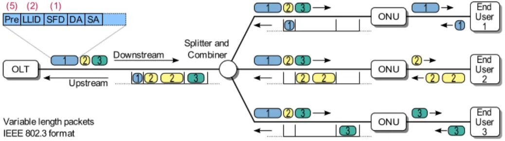
EFM Passive Optical Network (EFMP) interfaces introduce passive optical networks (PON), which is a completely new concept in Ethernet. An Ethernet PON (EPON) is a full duplex single fiber network with point-to-multipoint topology and data rates up to 1 Gbps7.
As shown in figure 7, it consists of a central optical line termination (OLT) and several optical network units (ONU), which are connected by a passive splitter/combiner. Each ONU connects one or several customers to the network. Packets from OLT to the ONUs, i. e. in downstream direction, are transmitted by the OLT to the splitter/combiner, which broadcasts them to all ONUs irrespective of the packet’s destination. The ONUs filter the packet stream and forward only those for the respective receiver while all other packets are dropped. For this selection, the OLT assigns a logical link identifier (LLID) to each ONU and marks all packets with the LLID of the receiver ONU. Vice versa, i. e. in upstream direction, all packets are transmitted to the splitter/combiner, which forwards the combined signal of all ONUs without any processing to the OLT. Accordingly, ONUs never receive the signal transmitted by another ONU.
B. Medium Access
It is obvious that in downstream direction, the medium is dedicated to one sender, namely the OLT, whereas in upstream direction it is shared. Historically, Ethernet is well suited to deal with a shared medium. Nevertheless, Ethernet’s typical medium access scheme CSMA/CD is not applicable as sensing is not possible. Thus, to control the EPON, the multi-point control protocol (MPCP, [5]) has been introduced. The MPCP is implemented in the MAC control layer and centrally coordinates the medium access of the ONUs based on the time division multiple access (TDMA) principle.
Besides, it allows to dynamically distribute the transmission capacity among the ONUs by adjusting the duration of the time slots. For this, the OLT signals each ONU the start time and duration of its next time slot at least every 50 ms. During this time slot the ONU may transmit user data and signal the current filling level of their transmission queues to the OLT. Based on this level information a scheduler in the OLT allocates further time slot to the ONUs. As the scheduler is not specified, many different scheduling strategies can be implemented (cf. [48]).
C. Link level OAM
The task of link level OAM is to allow a network operator to manage and monitor the path between two MAC layer entities, e. g. between the OLT and ONU. For this, the OAM sublayer has been defined as client of the MAC or MAC control layer with a slow protocol, i. e. a protocol with limited data rate [49].
OLT
Splitter and Combiner Upstream
Variable length packets IEEE 802.3 format End User 2 1 2 2 3 ONU 2 2 2 1 2 3 2 2 Downstream 1 2 3 Pre LLID SFD SA (5) (2) (1) DA ONU End User 1 1 1 1 1 2 3
ONU UserEnd 3
3 3 3
1 2 3
Fig. 7. Downstream and upstream traffic flow of an EPON
It relies on in-band signaling and transmits dedicated OAM frames via the MAC and PHY that is also used for user data. Such OAM messages may be sent several times in order to increase the reliability in situations with high error rates. It must be noted that the entire system can be used with any PHY and is thus neither limited to the local-loop nor to access networks.
Besides the discovery of the OAM capabilities of the neighboring nodes, there are three kinds of functions provided by link level OAM. First, data terminals can signal critical and non-critical events. While non-critical events are dedicated to the permanent supervision of error rates in defined time intervals (several symbols, frames, etc.), critical events are signaled if no bidirectional message exchange is possible. The most prominent critical event is a link fault, which is signaled if the receive path is broken. Second, for fault localization the remote loop back mode has been introduced. In this mode, the OAM sublayer reflects all received frames to the sender. This allows testing the MAC-to-MAC path. Third, as the lower layers in Ethernet only poorly inform their neighbors about errors, a variable retrieval mechanism is defined. This allows to read objects from the remote station’s management information base.
V. INDUSTRIALETHERNET
After the IEEE began to standardize Ethernet, different vendors (e. g. Siemens, [50]) adopted Ethernet for industrial applications. Today, the vendors mostly use the term indus-trial Ethernet for Ethernet-based solutions. In contrast to the Ethernet of corporate LANs, industrial Ethernet has to fulfill enhanced requirements such as time synchronization, (hard) real-time operation, and high availability. Furthermore, industrial Ethernet connectors and hardware have to meet ambient condition requirements of factory equipment such as electrical noise, vibration, temperature, and durability [51]. The driver was to reduce the steadily increasing costs and complexity as well as to connect a wide range of devices in the factory automation and control infrastructure. A further objective was to interconnect the factory and the office net-work for simple remote access to individual devices. Besides, Ethernet bandwidth and its further development promised to cover future needs [52], what it does to this day.
In recent years, more and more devices have come with a built-in Ethernet interface. Since Ethernet has been adapted to fulfill industrial requirements, it has started to replace fieldbus technologies such as Profibus [53] and Sercos [54], which
are close to reaching their capacity limits. The trend of
using Ethernet in industrial environments also affects related fields of application with similar requirements. Nowadays, Ethernet satisfies communication needs in many embedded networks, e. g. in marine applications and building automation. Traditionally, these have also been the domains of fieldbuses, which are gradually replaced by Ethernet.
A. Networking requirements
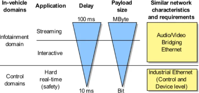
Industrial networks have to transmit information (e. g. temperature or position data) between sensors, actors, and controllers. In factory automation, we categorize network-ing components and technologies accordnetwork-ing to performance characteristics, exchanged information types, and cost. The performance characteristics comprise the number of attached devices, data rate, physical network size, response time, pay-load size, and frequency of data exchange. We thereby classify the networking components and technologies in hierarchical levels. Typical levels are the plant level, the control level, and the device level [55], [56]. The advantage of Ethernet is its potential to cover all levels as a single integrating networking technology.
The plant level comprises an entire production facility and connects a large number of factory cells and machine process controllers. This level tolerates reaction times up to several hundred milliseconds [57]. The control level connects a moderate number of specialized computing devices such as machine control systems over a moderately large area. In this level, the reaction times have to be smaller than 10 ms [58]. The device level enables the communication between sensors and actuators and requires normally a response time smaller than 1 ms with a jitter of less than 1 µs [59] for motion control with high frequency and small payloads [57]. Figure 8 depicts these differences of performance characteristics. The levels also structure the information flow required for factory and process automation [58].
B. Real-time Ethernet Solutions
Today, a number of different real-time Ethernet solutions supporting different classes of QoS exist. Due to the multi-tude of solutions and the history of their development, it is not possible to give a clear-cut definition of the term real-time Ethernet. One major criterion is whether a solution is compatible with IEEE 802.3 compliant devices or not. De-cotignie [60] classifies industrial Ethernet solutions according to their degree of compatibility with commercial off-the-shelf
Control level Latency Device level Plant level Response time Message frequency Transfer size
ms sec MByte rare
< 1 ms ms Bit often
Fig. 8. Networking requirements and characteristics of the levels in an industrial environment [55], [56]
(COTS) Ethernet technology: (1) interoperable homogeneous, (2) interoperable heterogeneous, and (3) non-interoperable. All these solutions carry the generic label industrial Ethernet or real-time Ethernet, even though they describe different and mostly incompatible technologies [60].
1) Interoperable, homogeneous solutions: Interoperable
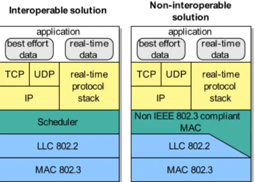
and homogeneous solutions build on IEEE 802 standards, as shown in figure 9, and thus are compatible with IEEE 802.3 compliant devices, i. e. devices implementing the following improvements are able to communicate with COTS Ethernet devices. The use of switches and full duplex links eliminates collisions. This makes QoS predictions easier and in turn enables the use of Ethernet as an industrial network for distributed real-time applications. As defined in the IEEE 802.1Q standard, Ethernet allows frame tagging that enables traffic prioritization and a separation of real-time and best effort traffic (which gets the lowest priority). Bridges can handle up to eight traffic classes, although in practice they only use four [60].
With respect to higher layers, two approaches exist. On the one hand, both real-time and best effort traffic can use the TCP/UDP/IP protocol suite. This solution allows transparent communication over network boundaries [59], but guarantees only relative QoS. The second option implements an additional real-time protocol stack, i. e. the real-time data bypasses the TCP/UDP/IP protocol stack and thus avoids potential delays introduced by these protocols [59].
An example of an interoperable, homogeneous solution is the Ethernet industrial protocol (EtherNet/IP, [61]). This solution uses tagged Ethernet frames and assigns real-time frames the highest priority [59].
Although the use of bridges and traffic prioritization avoids collisions, it does not make Ethernet deterministic. For ex-ample, if the buffer size inside a switch is too small to store simultaneously arriving frames temporarily, an overflow of the buffer and frame losses occur [60]. Therefore, the industry developed and adopted enhanced solutions. One such approach is the implementation of an additional traffic scheduler on top of Ethernet to regulate the traffic. It can take the task of a traffic smoother proposed by Kweon et al. [62], which is located between the transport layer and the data link layer, as shown in Figure 9, and smoothes data streams between these two layers. Its implementation requires enhancements of the protocol stack at the end systems. The MAC protocol, however, remains unchanged. Therefore, it runs on IEEE 802.3
compliant hardware.
Such a traffic scheduler can be a traffic shaper or a token bucket. This leads to smooth traffic in which messages arrive at a constant rate and not in a bursty manner. A traffic regulator delays bursty traffic for longer periods and thus improves the network performance [60].
In recent years, several authors [57], [62]–[75] have sug-gested and analyzed the real-time behavior of these solutions, some of them making additional assumptions like limited network load. Others analyze the delay bounds by using the priority field in the Ethernet frame, where the real-time traffic is given the highest priority, like in EtherNet/IP, and the best effort the lowest priority.
2) Interoperable, heterogeneous solutions: The solutions discussed in this section are also able to communicate with IEEE 802.3 compliant devices. However, their key to guar-antee real-time capabilities is the exclusive use of modified switches [60]. No other intermediate devices, hubs, switches, or routers are allowed. Otherwise, the communication falls back to the legacy best effort service of Ethernet, which is insufficient for real-time applications.
An example of such a solution is EtheReal [76]. This so-lution provides bandwidth guarantees by connection-oriented operation. When a device wants to transmit real-time data, it tries to set up a connection via a reservation protocol. If enough resources are available, a switch forwards the connec-tion request to the next hop on the path. Each switch repeats this process until the last switch is reached and the connection is established. The last switch confirms the reservation by sending a message back. This approach is similar to the resource reservation protocol (RSVP, [77]).
Another more prominent example of an interoperable, het-erogeneous solution is Profinet [50]. It differentiates several classes of communication services by means of synchronous time-division multiplexing: An isochronous time, a real-time, and a non real-time service. Each time slot allows the transmission of several Ethernet frames. A central entity manages the assignment of isochronous transmission capacity in the first time slot of a cycle. In the following slots, the real-time frames followed by the non real-real-time frames are transmit-ted. A special Profinet switch forwards the isochronous real-time frames without any interpretation [59]. In the following time slots, the switch changes to normal Ethernet operation and interprets the destination address to forward a frame to the corresponding port.
3) Non-Interoperable solutions: Applications with high
timing requirements, e. g. motion control, usually base on non-interoperable solutions. Such solutions use an additional, deter-ministic MAC as depicted in figure 9 and can be implemented on COTS IEEE 802.3 compliant hardware. Decotignie [60] lists different types of deterministic MAC, which have been used over the last years. These types include TDMA, master-slave, token passing, slot reservation, and time packet release. Networks implementing such enhancements are isolated from regular Ethernet networks by bridges. All real-time guar-antees are lost in presence of traffic from regular IEEE 802.3 devices due to the different MAC protocols. A representative example is the Ethernet for control automation technology
Interoperable solution Non-interoperable solution LLC 802.2 Scheduler application best effort data real-time data real-time protocol stack UDP TCP IP MAC 802.3 MAC 802.3 LLC 802.2 Non IEEE 802.3 compliant
MAC application best effort data real-time data real-time protocol stack UDP TCP IP
Fig. 9. Real-time Ethernet solutions
(EtherCAT, [78]). It uses the Ethernet frame format in a ring topology [58]. A master generates an Ethernet frame with a slotted data field. Each device allocates a number of slots and removes or adds information there. This information can be I/O information as well as TCP/UDP/IP data. Due to the on-the-fly processing, EtherCAT reaches a cycle time of 30 µs [58]. If required, the EtherCAT protocol may be tunneled through IEEE 802.3 compliant or IP-based networks in UDP packets, however without real-time guarantees.
C. Topology and Availability
Unlike in the office environment, most devices in an indus-trial network include an embedded bridge, which results in three possible topologies: line, ring, and tree. In the first two cases, each embedded bridge has three ports, the device being connected to one of them. The other two bridge ports are used to connect to adjacent switches. R¨uping et al. analyze these topologies in [79] with respect to the transmission delay. They show that the tree topology performs best, the ring topology second, and the line topology worst. In addition, the tree topology requires a smaller number of switches.
Industrial applications need highly reliable communication between several devices, not only between a client and a server as in the corporate LAN. Therefore, redundant links are deployed for resilience, e. g. in a ring topology. Less time-critical applications can cope with a higher recovery delay and the topology reconfiguration by (R)STP is sufficiently fast to recover from a failure. In contrast, (safety-critical) real-time applications require the parallel operation of redundant networks. Today, a number of redundancy methods to ensure a high availability exist. The International Electrotechnical Com-mission (IEC) is working on standards that define redundancy schemes suitable for industrial Ethernet networks. Kirrmann and Dzung [80] discuss redundancy requirements and classify redundancy methods.
VI. AVIONICSETHERNET
Over the last thirty years, the ARINC 429 [81] data bus has been widely used in various civil avionics applications. However, the increasing complexity of avionics systems is pushing this traditional data bus well beyond the limits of its bandwidth (100 kbps). In order to overcome these limitations, Boeing proposed the ARINC 629 [82] data bus. It offers a
2 Mbps multi transmitter bus supporting up to 120 nodes. However, this protocol has not gained general acceptance, due to high complexity and development cost. Hence, another solution that follows the new trend of using COTS technology was proposed to reduce the development costs and facilitate the maintenance process. A commercial standard (ARINC 664, [83]) and a specific aircraft implementation known as avionics full duplex switched Ethernet (AFDX, [83]) have recently been developed to define the use of switched Ethernet in aircraft. This latter has been successfully integrated into new generation civil aircraft like the Airbus A380.
A. Requirements
Avionics requirements concern both technical aspects and cost. The former consist of performance, safety, scalability, maintainability, and environment requirements. First,
perfor-mance requirementsconcern:
1) the applicative latencies that have a magnitude order of milliseconds and an allowed bounded jitter and have to respect deadline constraints;
2) the throughput that has to be at least 100 Mbps to guarantee the aircraft a viability of thirty years or more; 3) deterministic behavior where the system must be able to
deliver correct information in a predictable manner. Second, safety requirements include:
1) reliability where a service continuity has to be guaran-teed and mechanisms to detect, correct, or ignore errors have to be available;
2) integrity with a very low error rate;
3) availability that is often brought by redundant architec-tures;
4) security by supporting network domains with different security levels.
Third, we find scalability and maintainability requirements where the system has to support easy addition, removal, and maintenance of any node on the network to be viable for future evolutions. Finally, environment requirements impose compat-ibility with aircraft conditions (electromagnetic interference, vibration, heat, etc.) on the network.
Concerning cost requirements, a trade-off between the price and availability of network components and the deployment effort is required. Certainly, the use of a COTS technology has many advantages like increasing the number of vendors and thus reducing the component prices. However, the impli-cations of a new network on the existing appliimpli-cations (avionics functions) have to be taken into account by adding mechanisms to guarantee compliance.
We give an overview of the AFDX in section A. Section B surveys other works trying to extend the Ethernet’s imple-mentation in military avionics context.
B. AFDX standard
The AFDX standard [83] defines protocol specifications (ARINC 664 part 7) for the data exchange between avionics subsystems. This protocol represents an analogy to the ARINC 429 bus thanks to the virtual link (VL) concept that gives a
DA SA T IP Header Destination Address (DA)
UDP Header UDP Payload (min. 17, max. 1471 B)Avionics Subsystem Message Seq.No. FCS Ethernet Header
AFDX Frame Ethernet Frame
6 6 2 20 8 variable 1 4
Constant Field Virtual Link ID
2 4
Source Address (SA) Constant Field 1 3 Network ID Equipment ID Interface ID 1 1 Interf. ID 00000 Location ID Side ID Domain ID 0000
Fig. 10. AFDX frame format
way to reserve a guaranteed bandwidth and provides a simple transition for existing avionics functions. The VL defines a logical unidirectional connection between one source and one or more destinations. Thus, it shows multicast characteristics with one end system representing the source of a given VL.
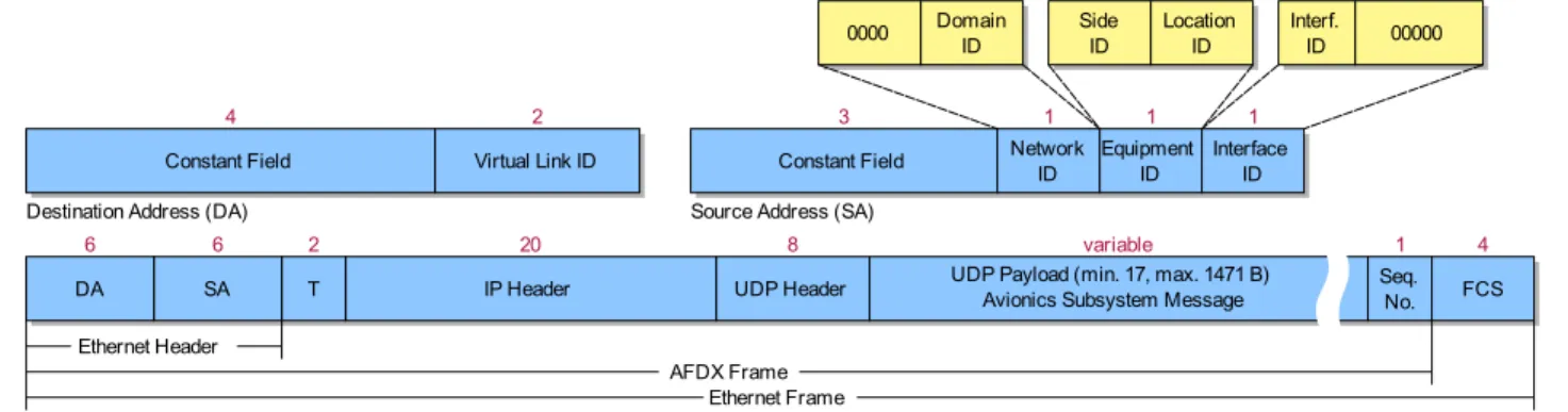
1) Functional description: The AFDX topology is a closed network topology and consists of interconnected switches and end systems. An end system is used to connect each avionics subsystem to the network, but it can also support multiple avionics subsystems where partitions are used to provide subsystem isolation within the same end system. Each end system has two direct bi-directional connections to two redundant switches to guarantee the system’s availability. A MAC address, as depicted in figure 10, identifies the end systems. The source address is a unicast address and represents a unique end system, whereas the destination address is a multicast address where the VL identifier is embedded.
Each end system can send data to multiple VLs. Thus, like the partition mechanism used to isolate subsystems within an end system, a similar mechanism is needed to isolate VLs to prevent interference between them. Hence, for each VL, the transmission rate and the maximal frame size are limited and defined a priori. Each VL has two main parameters:
• The bandwidth allocation gap (BAG) that presents the
minimal inter-arrival time between two frames sent on the VL. It ranges in powers of 2 from 1 ms to 128 ms;
• Lmaxthat is the largest Ethernet frame length transmitted on the virtual link.
All VLs generated by the same end system are controlled and scheduled by a VL scheduler inside each end system. This scheduler ensures that each VL respects its associated rate and length limitations and is responsible of multiplexing the different VLs. The management of the VLs by the end system is called traffic shaping. Each end system also integrates redundancy management to deal with the data received and transmitted on the redundant connections. The transmitting end system sends the same frame using two redundant paths to the same receiving end system. The receiving end systems choose the first valid frame.
The switches used in AFDX implement static configuration tables to define the associated physical ports for each VL. When a message is received, it is routed to its destination port(s) based on the VL. Hence, the STP and the address
resolution protocol (ARP, RFC 826 [84]) mechanisms are not necessary and disabled. These switches work in store-and-forward mode to check frame integrity and discard invalid frames. Furthermore, they ensure that each port sends correct VLs by means of policers. Frames that do not respect the associated VLs characteristics are discarded.
2) Extensions to IEEE 802.3 and 802.1D: The AFDX
specification [83] defines compliance degrees with regard to Ethernet and IP standards and distinguishes two types of networks: compliant network and profiled network. Compliant networks apply standard specifications. They are used for non-critical applications. Profiled networks require some exten-sions to the Ethernet standard to support avionics require-ments. They include two major extensions.
• Extensions to 802.3 standard: The traffic is controlled inside each source by using the VL concept and traffic shaping technique to guarantee the characteristics of each generated flow. For each VL, a sequence number is added to the Ethernet frame (1 byte field that occurs just before the FCS field). This is mainly used within each end system for redundant networks and for the integrity checking of received frames on the same VL to control the arrival order.
• Extensions to 802.1D standard: AFDX switches are
aware of VL characteristics and include policers that enforce the VL traffic contracts. Violating frames are rejected.
Extensions to standards and conception choices, like a statically defined topology and VLs, enable the deterministic behavior of the network [85], [86].
C. Extension to Military Avionics
The integration of the AFDX standard in the Airbus A380 was a great success in civil avionics. Therefore, full duplex switched Ethernet became attractive for next generation mil-itary aircraft. It is worth to note that AFDX could not be used for military applications. In fact, the requirements of communication protocols are distinct in civil and military ap-plications. AFDX has been defined to provide traffic isolation and bandwidth guarantee along with a guaranteed latency to all traffic flows, whereas military applications need several service classes in severe military environments where bandwidth may not be the primary design concern.
![Fig. 8. Networking requirements and characteristics of the levels in an industrial environment [55], [56]](https://thumb-eu.123doks.com/thumbv2/123doknet/3695886.109766/12.918.129.395.78.231/fig-networking-requirements-characteristics-levels-industrial-environment.webp)
![Fig. 12. Topology and interworking of an AVB domain [105]](https://thumb-eu.123doks.com/thumbv2/123doknet/3695886.109766/18.918.75.854.85.575/fig-topology-interworking-avb-domain.webp)
