HAL Id: hal-01325205
https://hal.archives-ouvertes.fr/hal-01325205
Submitted on 1 Jun 2016
HAL is a multi-disciplinary open access
archive for the deposit and dissemination of
sci-entific research documents, whether they are
pub-lished or not. The documents may come from
teaching and research institutions in France or
abroad, or from public or private research centers.
L’archive ouverte pluridisciplinaire HAL, est
destinée au dépôt et à la diffusion de documents
scientifiques de niveau recherche, publiés ou non,
émanant des établissements d’enseignement et de
recherche français ou étrangers, des laboratoires
publics ou privés.
reinforced foam core braided composite structures
Olivier Dorival, Pablo Navarro, Steven Marguet, Caroline Petiot, Michel
Bermudez, Didier Mesnagé, Jean-François Ferrero
To cite this version:
Olivier Dorival, Pablo Navarro, Steven Marguet, Caroline Petiot, Michel Bermudez, et al..
Experi-mental results of medium velocity impact tests for reinforced foam core braided composite structures.
Journal of Sandwich Structures and Materials, SAGE Publications, 2016, �10.1177/1099636216650990�.
�hal-01325205�
medium velocity
impact tests for
reinforced foam core
braided composite
structures
Reprints and permission:
sagepub.co.uk/journalsPermissions.nav DOI: 10.1177/ToBeAssigned www.sagepub.com/
Olivier Dorival
1,2, Pablo Navarro
2, Steven Marguet
2, Caroline
Petiot
3, Michel Bermudez
3, Didier Mesnag ´e
3and Jean-Franc¸ois
Ferrero
2Abstract
Absorbing impact energy at sub-system level is an attractive idea that is emphasized by new composite reinforcement techniques such as stitching or pinning. This paper reports experimental results of medium velocity impact tests carried out on several arrangements of reinforced foam/braided composite structures. The tests consisted of a steel ball shot at a velocity of 110 m/s from a gas gun impacting the structures on their leading edge. Post-mortem tomography analysis delivered very rich information which shed light on the damage mechanisms that the composite structures underwent. In addition, two fast-speed cameras were used to derive the energy absorption during the impact. Absorption capabilities were also compared with those of dynamic crushing tests (reported in a companion paper) and some designs clearly exhibited promising behavior as shock absorbers.
Keywords
Foam/carbon-kevlar braided composite structures, impact energy absorption, gas canon ball impact tests, composite reinforcement, composite damage mechanisms, shock absorbers, sandwich structures, computed micro-tomography.
Introduction
Over the past decades, weight optimization has been an ongoing challenge in a number of fields such as aeronautics, marine, automotive technologies, to name but a few. Multi-materials, such as composites, offer infinite possibilities to achieve this goal but, at the same time, they make predictions difficult with either analytical or numerical models. This is particularly the case in the context of composite structures which may
experience impact loadings (1) due to tool drops, runway debris, bird strikes, hailstorms
or ballistic loading, which make experimental analysis still a major method in both the academic and industrial research in this field. Among other lightened structures that can experience impacts during their life, foam core composite structures have shown interesting performances and have consequently raised significant interest. One key step
is to identify the modes of damage raised by impact loadings. In (2) foam-skin debonding
was found to start the initiation of damage under drop weight tests. In (3) composite
structures similar to helicopter blades were impacted by a steel ball shot at a velocity of up to 140 m/s using a gas gun and the authors identified the following damage scenario: damage of the front edge, skin-foam delamination, damage of the roving and penetration. In order to improve the response of foam core composite structures to impact loading, one can act on the facesheets or on the core. Concerning the facesheets, some studies have shown that incorporation of additional elements in the resin prior to molding
can increase the impact resistance by a few percent (4;5;6). A more evident way of
reinforcing facesheets relies on the reinforcement of the skin used for the external faces.
For instance, Villanueva and Cantwell (7) compared fiber metal laminate reinforced skin
with unidirectional glass fiber polypropylene and woven glass fiber polypropylene under
medium velocity impact. Zhou et al. (8) studied the impact damage and energy absorption
of 3D braided composite tubes and found a good correlation between experimental and numerical results.
However, since impact loadings mainly put a strain on the out-of-plane behavior, which is more dependent on the core materials than on the facesheets, a number of researchers have focused on the core properties of foam core sandwiches. Anderson
and Madenci (9) compared damage after low velocity impact on sandwiches made
of carbon fabric with two thicknesses and a core made of either Rohacell foam or
honeycombs with two densities for both types of cores. Cantwell et al. (10; 11; 12)
1Icam, site de Toulouse, 75 avenue de Grande-Bretagne, 31076 Toulouse Cedex 3, France
2Universit ´e de Toulouse; Institut Cl ´ement Ader (ICA); INSA, UPS, Mines Albi, ISAE, 135 av. de Rangueil, 31077 Toulouse Cedex, France
3Airbus Group Innovations, 12 rue Pasteur, 92152 Suresnes Cedex, France Corresponding author:
Olivier Dorival, Icam, site de Toulouse, 75 avenue de Grande-Bretagne, 31076 Toulouse Cedex 3, France Email: olivier.dorival@icam.fr
investigated the influence of various foam properties on the quasi-static and low/medium
velocity perforation resistance of composite sandwiches. Nasirzadeh and Sabet (13)
found significant influence of the foam density under medium velocity ballistic impact (100-150 m/s) . They showed that medium density foams had better energy absorption and better ballistic limits than low and high density foam sandwiches. Some studies
(14;15) also investigated the impact resistance of sandwiches involving layered graded
foam cores and showed that they can outperform monolithic foam core sandwiches in terms of impact resistance.
Besides playing on the mechanical properties of the foam core, a growing number of studies have focused on possible additional reinforcements of foam cores by means of discrete elements such as lattices, pins, stitches, etc. The idea is to stiffen the sandwich behavior in the out-of-plane direction, to delay core/facesheets debonding, while creating numerous small sources of dissipation during the crushing stage. Various hollow cores (without foam) have been developed and tested; however, foam filling is regularly found to stabilize the reinforcements thus avoiding premature buckling. It also provides additional modes of energy consumption by crushing and densification
of the foam. Pitarresi et al (16) studied several reinforced sandwich structures used as
walls of hollow rectangular structures. Foam reinforcements were shown to improve energy absorption during quasi-static edgewise compression as they maintain the
structure in a continuous crushing process. Li and Muthyala (17) showed the improved
characteristics of a sandwich made of an orthogrid stiffened syntactic foam core and
glass/epoxy facesheets under low velocity impact. Zhang et al (18) studied a sandwich
composed of aluminum pyramidal lattice core surrounded by polyurethane foam between unidirectional carbon/epoxy laminates. The foam is shown to improve the compression stiffness of the lattice core by improving the resistance of each truss beam to buckling.
Vaidya et al. (19) tested 3D curved core piles woven into the skins with/without foam
under low velocity impact. They found that the main damage mechanisms without foam were the buckling of the core pile and the rupture of the facesheets, whereas with foam, the structure mainly underwent foam core crushing with core pile failure. Wang
et al. (20) determined the static properties of foam sandwich reinforced with composite
columns with various reinforcement densities. Reinforcements were found to enhance the
plasticity capability of the structure. Zhou et al (21) studied the behavior of PVC foam
core reinforced with glass or carbon composite under quasi-static compression and low velocity impact test. They found that compressive strength and energy absorption can be optimized by choosing a medium density foam combined with thin, but stiff, carbon rods.
Vaidya et al. (22) showed that foam core sandwiches with foam reinforced by titanium
Z-pins or glass/epoxy Z-Z-pins, when subjected to high strain rate impact testing, experienced
limited foam crushing compared to the unreinforced foam core. Nanayakkara et al. (23)
reported enhancement of Z-pinned sandwich composite structures under quasi-static global compression.
Through-the-thickness stitching is another interesting reinforcement technique which brings additional stiffness and avoids core crack propagation. Stitching density was
found to be a key parameter. Stanley and Adams (24) reported that stitching greatly
tests, out-of-plane tensile tests, core shear tests and edgewise compression tests, as well
as for low velocity indentation tests. Similar results were reported in (25) and (26),
except for the energy absorption; divergences may be due to the different stiffness and
mass characteristics used for the foam and the reinforcements. Xia and Wu (27) also
found that reinforcements enhanced the performances during low velocity impact on a polyurethane foam sandwich with plain glass fabrics reinforced by kevlar
through-thickness stitches oriented at 90◦. Whether the additional mass brought by the stitches
finally deteriorates the specific properties (i.e. properties per unit mass) of the structure
is still an open question and researchers have come to different conclusions (25; 28),
again depending on the parameters used in the different studies. Stitching orientation is also a significant parameter. Angle cross-pattern stitching was found to enhance the
quasi-static performances even more than 90◦stitching, in particular in core shear testing
(24). Influence of the stitching angle on the impact performances has been the focus
of several papers. Singh and La Saponara (29) suggested that 90◦stitching may not be
the best choice for damage tolerance. In (30), it was shown that cross-pattern stitches
improved the low velocity impact response of glass/polyurethane foam sandwiches by limiting core/skin debonding. Stitch breaking was found to be the dominating energy
consumption mode. Samlal et al. (31) arrived at similar conclusions for 45◦ stitching
under low velocity impact tests. Tekalur et al. (32) found that effects of
through-the-thickness stitches were also important in very high velocity impacts (1100 m/s) as stitches helped the transfer of the force to the back skin (this is not the case with unstitched foam sandwich since the dynamics are very high frequency). However, Guan et al.
(28) reported that the blast resistance of stitched sandwich panels was not significantly
enhanced due to the additional mass to be considered. Finally, diverging conclusions clearly suggest that there is a need for optimization of the stitching materials and parameters.
Although energy absorption strongly depends on the damage mechanisms, precise investigations about the damage pattern are seldom studied by means of non-intrusive
techniques such as tomography or X-ray techniques. Feng and Aymerich (33) analyzed
PVC foam/carbon epoxy sandwiches under low velocity impact tests at several impact energies and showed a good agreement with FE modeling. Damage facesheets were carefully analyzed by X-radiography.
In this paper, we report experimental results of medium velocity impact tests performed on several designs of foam based composite structures that may be involved in several aircraft parts such as rotor blades, wing parts, fuselages, etc. The various specimens were designed with the idea of developing deformation and damage mechanisms of high convenience for absorbing the projectile kinetic energy during the impact. Following this idea, all the specimens were designed with the same external
shape as illustrated in Fig. 1. The same medium density foam and the same external
braidings were used. However the designs differ by various reinforcement techniques involving inner composite walls and/or discrete reinforcement techniques such as the use of inner walls, stitching and sewing. All the designs were provided by Airbus Group according to Airbus standards or Airbus specifications. For cost reasons, the number of samples for each design was limited. We chose to challenge each design under
various loading conditions, including dynamic crushing tests and gas gun tests. For these reasons, two samples were tested in gas gun tests under the same conditions to check the repeatability, and eventually a third one was performed to validate in case the test results varied due to experimental vagaries. In this paper, we report only the comparisons of impact tests on the leading edge with 20 mm steel ball. The damage scenario identified on the most promising sample is also validated with a more energetic 30 mm impact test. This paper is organized as follows: after the experimental set-up is described, post-mortem analyses of each specimen are reported based on tomography analysis. They provide a very precise understanding of the damage mechanisms developed during the impacts. A more energetic impact test is then reported concerning the design which was clearly identified as the most promising, in order to validate the damage scenario assumed. Energy absorption values are then given which allows us to emphasize the strengths and weaknesses of each design. Finally, these results are compared with that of
low velocity dynamic crushing tests detailed in a complementary paper (34). Although
the two types of loadings are basically different, some reinforcement techniques look very promising in terms of their capability to absorb impact energy either during a large crushing event or a medium velocity localized impact.
Direction of impact x y z 200 45° 45°
Figure 1. Dimensions of the external shape for any design.
Experimental set-up
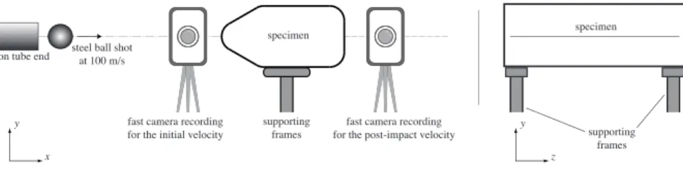
A gas canon was used to shoot a 20 mm diameter steel ball at a speed of 110 m/s. The principle was to accelerate the ball in a tube in which a pressure wave was suddenly created. With this in mind, the pressure in a pressurized tank was increased to a given value and was released when the trigger started. The pressure then pushed the ball, which was stabilized in a foam part. The velocity of 110 m/s was reached when the ball exited from the tube. The projectile impacted the composite structure on its leading edge with
steel ball shot at 100 m/s
fast camera recording for the initial velocity
fast camera recording for the post-impact velocity specimen
supporting frames canon tube end
x y z y supporting frames specimen
Figure 2. Experimental set-up.
an impact energy of 198 J. During the tests, the structure was simply supported on a
solid frame as illustrated in Fig.2. The aim was to avoid any external force or dissipation
phenomenon due to the supporting tool, in order to consider the specimen’s edges as free during the energy analysis. For this, the contact areas between the specimen and the frame were small and located close to the sides of the specimen.
Post-treatment of these tests was composed of several parts. Firstly, 3D computed tomography (CT) was used to scan each specimen for damaged zones. This provided a very precise understanding of the damage and led us to suggest a damage scenario for each type of reinforced structure. Apart from the observation of the damage, it was interesting to look at the energy absorption during the impact. For this, two fast cameras
were used, see Fig.2: the first fast camera recorded the motion of the ball before the
impact in order to get the initial kinetic energy; the second camera recorded the motion of the specimen and the ball (in case it exited from the specimen) after the impact, in order to get the output energy of the specimen. From the recordings, the motion was tracked
based on a DIC technique described in (35), and velocities were used to complete an
energy balance analysis.
Analysis of damage mechanisms in impacted designs
Reference design D1
Figure 3. Reference design D1.
Design D1 is the reference, see Fig.3. It is composed of a foam block wrapped in
elastic modulus 105 MPa, shear modulus 42 MPa, compressive strength 1.7 MPa, tensile strength 2.2 MPa, shear strength 1.4 MPa). The composite consists of three layers of
2D-braiding composed of aramid 12K fibers (area weight 176 g/m2
, tensile strength 2.92
GPa, tensile modulus 109 GPa) injected with HexFlow RTM6 resin (density 1110 kg/m3
, tensile modulus 2.89 GPa, tensile strength 75 MPa, flexural modulus 3.3 GPa, flexural
strength 132 MPa) and oriented at ±45◦, see Fig.1. The braidings consisted of a four
harness satin (crowfoot). The theoretical thickness of one layer was supposed to be 0.3 mm, but due to manufacturing vagaries, the actual thickness was found to be about 0.6 mm for one layer. Note that the same external shape and the same materials were used for all the designs presented.
The impact on design D1 was very clear to understand from the camera pictures and direct observation of the damage was simple. For this reason no tomography analysis was carried out on this design. The damage scenario observed was as follows: the projectile penetrated the leading edge by breaking the resin and the fibers of the front braidings and crushing the front foam under the braidings. It did not deviate and advanced in a constant direction inside the foam core by crushing and densifying the foam in a very localized zone (a very straight and narrow hole was observed with diameter almost equal to that of the ball). The ball reached the rear face and exited by breaking the resin and fibers. Once again, it did not deviate when passing through the rear braidings.
Effect of using a second, similar braiding
Figure 4. Design D2.
Starting from the same external shape, design D2 consists in using a second braiding
inside the foam as illustrated in Fig.4. For this, an inner foam block with a similar shape
and smaller dimensions is used. It is covered with three layers of semi-impregnated
3D-Interlock braiding in aramid 12K fibers (±45◦, 1 mm thick). This assembly is surrounded
with foam which is composed of two bonded parts. The whole group is covered with three layers of 3D-Interlock braiding of aramid 12K fibers and is then injected. The internal braid was intended to remain a dry net in order to keep its softness during impact. However, micro-cuts performed revealed that, unfortunately, some resin infused into the internal net.
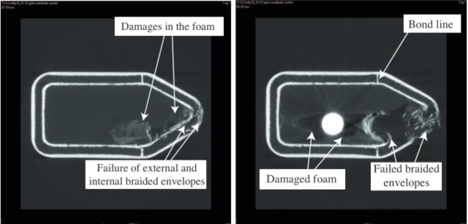
Impact damage was checked under a micro-computed tomography non-destructive
Damages in the foam
Failure of external and
internal braided envelopes Damaged foam
Bond line
Failed braided envelopes
Figure 5. 2D views alongx-yof design D2.
Failed envelopes
Failed back face of internal braided envelope
Failed external and internal leading edge
braided envelopes
Figure 6. 2D views alongx-zof design D2.
planes, x-y and x-z, of the impacted configuration D2 sample with details of the impacted
region (x is the direction of the ball’s motion, see Fig. 1). Image filtering was used
in order to reveal damage in the areas with less density (e.g. foam core). The views correspond to cross-sectional views in the plane containing the bullet or close to this plane. The left and right pictures present results with two contrasting parameters in order to emphasize either foam damage or braiding damage.
The scans illustrate the following damage mechanisms:
• in the leading edge, external and internal skins were perforated and the bullet
created a cavity in the foam (see Fig.5and6);
• when penetrating the design, the bullet slightly deviated towards the inferior part of
the sample ; the bullet was finally stopped at approximately 2/3 of the specimen’s total length;
• as damage in the foam was observed behind the final bullet position (see Fig.5and
6 on the right), the most probable scenario is that the ball compressed the foam
much more during the impact with the consequence that the compressed foam
broke the back face of the internal braided envelop (see Fig.6). During testing, an
out-of-plane deformation was actually observed with the high speed video camera recording the back face of the sample;
• the foam relaxation finally pushed the ball back to approximately the middle of the
sample;
• the failure of the back face internal braided envelop shows that limited further
absorbing capabilities are foreseen with configuration D2.
Effect of using a transverse wall
The idea of inserting a transverse wall was done by using two foam blocks covered with a layer of braiding. To achieve the same number of layers, the assembly was wrapped with two layers of braiding before injection. The side voids were filled with an aramid
dry tow injected with the same resin. The final Design D3 is illustrated in Fig.7.
Figure 7. Design D3.
The CT scan performed on specimen D3 revealed the following damage scenario as
illustrated in Fig.8and9:
• delamination and failure of the leading edge skin was caused by the impact
projectile probably under skin bending loading condition;
• prior to, and during, the leading edge skin failure, skin bending and failure firstly
created compaction, followed by damage in the foam core underneath the leading
edge skin, leaving a conical cavity in the foam core (see Fig.9);
• the bullet then hit the inner wall at 90◦, again creating an out-of-plane displacement associated with the bending of the inner wall;
• in a similar way to the first strike, the bent skin compacted the foam core on the
bent side of the inner wall, leaving a cone-shaped cavity (see Fig.9);
• the bullet (or the densified foam pushed by the bullet) then perforated the inner
wall and migrated following a tunnel-like path up to the center of the second foam block;
• a certain rebound is visible close to the sample outer face which shows a remaining
cavity. The cavity was created by the foam compaction. Further damage in the foam close to the back face outer wall are also visible;
• the braidings located on the back face do not show any damage.
Figure 8. Specimen D3 shown through reconstructed 3D scans after a impact perpendicular
to its leading edge.
Broken internal wall
Conical cavity in the front foam Conical cavity
in the rear foam
Effect of reinforcing the front bumper in design D3
Figure 10. Design D3R.
Design D3R is similar to the D3 design in which the front bumper is reinforced by
manual continuous sewing, as illustrated in Fig. 10. The front foam block was
pre-drilled (diameter 1.5 mm) with several holes. The sewing used doubled tow of carbon
6K for each hole with an increment of 7.5◦between the direction of each hole. The pitch
between two planes for sewing was 6 mm. The whole ensemble was injected with resin.
Failed braided envelope Impactor ball Failed braided
envelope
Figure 11. Design D3R shown through reconstructed 3D CT scans after impact.
The CT scan performed on design D3R after impact revealed the following damage
scenario as illustrated in Fig.11to13:
• failure of the leading edge skin was caused by the impact projectile under skin
bending loading condition;
• prior to, and during, the leading edge skin failure, skin bending and failure
firstly created foam compaction, followed by damage to the reinforced foam core underneath the leading edge skin;
Failed
internal wall Impactor ball Variable angle stitch pattern Multiple stitch
fragmentation
Stitches
Impactor ball
Internal wall failure Fragmented failure of stitches
under bending/shear loading
Figure 12. Design D3R after an impact perpendicular to its leading edge : (left)
cross-sectional view of 3D CT scan view after filtering, (right) 2D CT scan view showing a multiple failure of a stitch by effect of stitch bending along the ball’s path.
Cavity in foam
2D y-z plan stitch pattern
2D z-x plan of the impacted area of the specimen
Failed stitch heads Fragmentation of some
lateral stitches
Figure 13. Design D3R 2D and 3D CT scan views showing several stitch head failures and
the foam tunnel left by the ball’s path.
• the foam reinforcements were totally broken (see Fig. 12) along the axis of the bullet’s trajectory. Also the stitches located on the lateral side from the impact axis were forced to bend while the ball was passing through the sample;
• the lateral stitch bending generated multiple fragmentations of some of the stitches
(see Fig.12);
• the bullet then hit the inner wall at 90◦, again creating an out-of-plane displacement associated to a limited bending of the inner wall due to the joint through the stitches to the external envelope;
• the bent skin compacted the foam core on the bent side of the inner wall, leaving a
cone-shaped cavity;
• the bullet then perforated the inner wall and migrated following a tunnel-like path
up to the back face of the second block;
• the outer wall located on the back face partially failed. The bullet also remained in
the sample. The upper bumper stitch attachment on the inner wall probably limited the inner wall bending deflection before its failure on the lower bumper foam core. From the tomography analysis, one may conclude that the reinforced design D3R did not bring a significant improvement compared to design D3. However, an energy analysis, which will be given in a coming section, showed a slight improvement in the energy absorption that can be explained by additional dissipation capabilities offered by the possibility of stitch breakage.
Effect of using a longitudinal wall
Figure 14. Design D4.
Instead of using discrete reinforcements to improve the initial stiffness, Design D4 was made of two oblong foam blocks covered with one layer of braiding of carbon 12K
fibers, see Fig.14. The shape was completed by a front foam block and the rear void
was filled with an aramid dry tow. To ensure that the front edge included three layers of braiding, as in other designs, a core cap fabric was used to cover the front foam. The assembly was surrounded by an external braiding and was injected with resin.
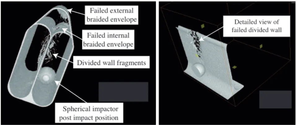
As for other sample configurations, micro-computed tomography non-destructive investigation technology was used in order to identify damage scenarios after impact.
Fig.15presents 3D views of the impacted configuration D4 sample. A cross-sectional
view by means of a 2D plan was performed in the software in order to show half of
specimen D4 with details of the impacted region. Fig. 15right view corresponds to a
cross-sectional view without external braidings for better visibility of the damage created in the inner wall.
Fig.16and17respectively present 2D views for plane orientation x-y and x-z of the impacted configuration D4 sample with details of the impacted region. Image filtering was used in order to reveal the damage in the areas with lower density (e.g. foam core). The views correspond to cross-sectional views in the symmetry plane of the bullet, or close to this plane.
The scans presented in Fig.15to17illustrate the following damage mechanisms:
• the leading edge skin was perforated and the bullet created a cavity in the front
foam;
• the strike of the bullet on the internal braided envelope damaged it; • consequently the dividing wall was broken and delaminated;
• the bullet was stopped by the back face of the external braided envelope of one of
the sub-structures;
• the ball final location indicated that very limited further absorbing capabilities
could be foreseen with sample D4 as in Fig.17(right picture), it seems that the
back face external braided envelop slightly suffered from the shock wave.
Spherical impactor post impact position
Divided wall fragments Failed internal braided envelope
Failed external
braided envelope Detailed view of
failed divided wall
Figure 15. Views of two different angles of 3D micro-tomography of sample D4’s global
impact damages.
Effect of reinforcing rear bumpers in design D4
Starting from the idea of strengthening oblong bumpers from design D4, Design D4R
oblong chambers and their carbon braidings were reinforced by stitching, see Fig. 18.
The stitches were made of carbon 6K fibers oriented at ±60◦from the symmetry plane
(that is +60◦in a given plane and −60◦in the next plane, the pitch between two planes
was 6 mm). The distance between two stitches in a given plane was 6 mm. Note that the two oblong chambers and their carbon braidings coverage were separately stitched before being assembled. To ensure that the front edge included three layers of composite as in other designs, a core cap fabric was put on the top of the front foam. The assembly was surrounded by an external braiding and was injected with resin.
Damaged foam Broken internal envelope
Wall debris Delamination
Figure 16. Four sets of 2D views alongx-yof design D4.
Foam core destroyed Leadingedge
Back face of the external braided envelope
Figure 17. 2D views alongx-zof design D4.
As for other sample configurations, micro-computed tomography non-destructive
investigation technology was used. Fig. 19 and20 present 3D views of the impacted
configuration D4R sample. A 2D cross-sectional view was performed in the specimen in order to show half of the D4R specimen with details of the impacted region. The views correspond to a cross-sectional views in the symmetry plane of the bullet, or close to this plane.
Fig.21and22present 2D views of the impacted configuration D4R sample with details
of the impacted region. Image filtering was used in order to reveal damage to the areas with lower densities (eg. foam core). The views correspond to a cross-sectional view
Figure 18. Design D4R.
Figure 19. Partial view of 3D micro-tomography of sample design D4R.
Regular network of stitches Perforated braided external skin Perforated braided
internal skin and damages
in the divided wall
Broken stitches
Void
Figure 20. Partial view of 3D micro-tomography of sample design D4R.
in the symmetry plane of the bullet, or close to this plane. The bright dots in Fig.22
correspond to the stitches.
Failure and delamination in the divided wall
Cavity in the foam Cavity in the foam Failed external braided envelope Breakage and delamination
of the divided wall
Cavity in the foam Failed external envelope
Zoomed view showing multiple breakage of stitches
Figure 21. 2D views alongx-yof configuration D4R.
Failed external envelope
Failed internal envelope Foam tunnel like cavity
Leading edge
Figure 22. 2D view in the impacted area alongx-z(left) andy-z(right) of design D4R after
• the leading edge skin was perforated and the bullet created a cavity in the foam
(see Fig.21);
• the strike of the bullet on the internal braided envelope damaged it (see Fig.19to
22);
• consequently the dividing wall was broken and delaminated (see Fig.20and21);
• the bullet was stopped by the stitches stabilized in the foam core in one of the
sub-structures (see Fig.19,20and21). It is interesting to note that the projectile was
stopped much sooner compared to other designs;
• the stitches contributed to the energy absorption as several stitch failures were
observed (see Fig.21);
• beneath the ball final location, a long part of reinforced foam did not seem to have
suffered any damage. None of the stitches seem to have moved from the initial
position (see Fig.20and22-left). Therefore, it appears that configuration D4R has
further absorbing capability potential;
• roughly half the height of the configuration D4R contributed to the energy
absorption capabilities as the bullet was stopped at mid-height with no damage observed beneath.
Test of D4R to a more energetic impact
In this section, a test was carried out with a steel ball of diameter 30 mm. For the sake of brevity, this test was only carried out on design D4R. The idea was to validate the damage scenario identified in the previous section with a different impactor. Design D4R was chosen because a change in the impactor size or the impact energy could be expected to change the damage scenario, due to the complex damage mechanisms involved. The impact speed was kept at 110 m/s, resulting in an impact energy of 667 J, which was 3.375 more energetic than with the 20 mm ball.
Hole in the outer braiding 30 mm steel ball Damaged inner walls Failed stitches
Figure 23. Partial view of 3D micro-tomography of design D4R after impact at 110 m/s by a
30 mm steel ball.
Fig.23presents a 3D view of design D4R impacted by the 30 mm steel ball. 2D
cross-sectional views were performed in the specimen in order to reveal details of the impacted region only. The figure reveals a clear hole in the outer braiding due to the penetration
of the ball. The breakage of the outer braid was probably caused by deformation and damage of the foam beneath the braid, followed by resin damage and breakage of the fibers under tension.
Failed external envelope
Braiding of the
inner wall Breakage and delamination of the inner wall
Delamination of the inner walls
Stitchs debris close to the ball
Figure 24. 2D view in the impacted area alongx-z(left) andx-y(right) of design D4R after
30 mm impact.
The inner walls, and in particular the mean wall, were completely destroyed. Stitch
debris were also visible. Fig.24gives more details about the damage of the inner walls.
The left figure shows that the path followed by the impactor up to the rear face was totally damaged on the exact diameter of the ball, suggesting that while progressing in the two oblong chambers, the ball totally destroyed the mean wall. Away from this path, the inner braidings look clearly undamaged. The right figure shows that the walls experienced delamination.
Multi-breakage of stitches No failure of the attachments to the skins
Figure 25. Partial view of 3D micro-tomography of design D4R after impact at 110 m/s by a
30 mm steel ball.
At the same time, numerous stitches were damaged. Fig.25gives some information
about the damage mechanisms of the stitches. As the inner wall was destroyed, one may assume that the attachment to the mean wall was lost, and that the stitches folded in the direction of the external braid to allow the progress of the ball. Most of the stitches
remained attached to the outer braids. Fig. 25also confirms that a single stitch often broke at several points. This is interesting information because this multiple failure mode dissipates more energy than a single one. Additionally, one can note that the stitch attachments remained totally undamaged. Stitch breakage essentially occurred far from the bonding to the braidings. As the impact energy was greater than for 20 mm projectile, the ball finally rebounded on the back face due to the elastic energy release of the foam and the external braid. When the ball came back, the stitches returned to their initial location due to the remaining attachment to the outer braid. These results confirm the damage mechanisms identified with the 20 mm impactor.
Energy absorption and comparisons with crushing tests
Fast camera pictures were used to measure initial and post-impact velocities. From the velocities, kinetic energy and, as a consequence, the energy absorption ratio and specific energy absorption (SEA) could be computed. The energy absorption ratio is the ratio of the energy absorbed during the impact relative to the initial kinetic energy. SEA is the ratio of the absorbed energy to the mass of the specimen. Note that SEA values were normalized with respect to that of reference design D1. The results are reported
in Table1. The energy absorption ratio are very similar and consequently, they do not
help distinguish the designs that have good potential to face impact events. However, one must pay the price for this improved potential, as the SEA indicates. Indeed, design D1, although less absorbant, shows the best SEA since it is the lighter design. On the other hand, design D4R, has the smallest SEA value, even though the other values are relatively close. Additionally and to be more precise, one can say that in D4R, the entire length of the design was not required to stop the ball. This means that the design dimensions, and in particular the reinforcement dimensions, and as a consequence its weight, could be optimized for a given impact energy.
In order to compare the designs, and taking into consideration the net mass used, it was convenient to give an idea of further potential for each design which would then confirm the possibility for the design to absorb a more energetic projectile. With this in mind, a “ball penetration indicator” was defined by capital letters as follows: “A” denotes a test in which the ball was stopped before reaching the middle of the sample (good potential), “B”: the ball was stopped before reaching the rear braidings (medium potential), “C”: the ball reached the rear braidings and the foam was crushed along the whole length (low potential), “D”: the ball damaged the rear braidings but stayed trapped (almost no potential left), “E”: the ball was not stopped during the test and exited the specimen (the specimen could not retain the impact at 110 m/s). The “ball penetration indicator” clearly highlights that designs D2, D3 and, above all, D4R are able to support more energetic loadings; all other designs have, at most, only the rear braiding resistance left.
Finally, Table1also shows the results from low velocity crushing tests reported in a
companion paper (34) in order to give a cross-comparison based on two different types
of impact loadings: while canon ball impact tests challenged the structures in a very localized manner, dynamic crushing tests showed their capabilities under global dynamic
good potential as an impact absorber for both types of loadings, due to its high stitching density. However the additional mass of the stitches obviously led to degraded SEA value for both cases. In the same time, good potential and low SEA value should be interpreted as the possibility to optimize the stitch density, consequently the mass and the SEA, for a given impact energy to be absorbed.
Design D1 D2 D3 D3R D4 D4R
Medium velocity tests
Energy absorption ratio [%] 80.1% 89.3% 84.6% 86.0% 84.7% 87.8% Specific energy absorption (normalized) 1.00 0.75 0.79 0.84 0.72 0.70
Ball penetration indicator E C C D D A
Low velocity crushing tests (results from (34))
Energy absorption ratio [%] 94% 84% 94% 91% 32% 84% Specific energy absorption (normalized) 1 0.49 0.68 0.61 0.22 0.46 Usable concept left [m] 0.024 0.039 0.048 0.047 0.016 0.062 Table 1. Energy absorption ratio and comparisons with crushing test results from (34).
0 0.2 0.4 0.6 0.8 1 A B C B A
Crushing reserve ratio (%)
P ot eni al i ndi ca tor D1 D2 D3 D3R D4 D4R 0 0.2 0.4 0.6 0.8 1 0 0.2 0.4 0.6 0.8 1
SEA in crushing test (normalized)
S E A i n m edi um ve loc it y i m pa ct t es t (norm al iz ed) D1 D2 D3 D3R D4 D4R
Figure 26. Comparisons between medium velocity impact tests and crushing tests. (left):
further absorption indicator and (right): SEA comparisons.
Conclusion
Several foam core composite structures reinforced by several techniques were submitted to medium velocity impact loading consisting of a 20 mm ball shot at 110 m/s on the leading edge. Computed tomography analysis clearly revealed the damage mechanisms for each design. The conclusions can be summarized as follows:
• in the reference scenario, the projectile penetrated the leading edge by breaking the
front braidings (compacting the foam underneath and bending the braidings) and it advanced by crushing the foam core. It reached the rear braidings, broke them and exited the sample;
• all the reinforced designs were able to trap the projectile inside. The reinforcements
were capable of strengthening the foam core as well as offering different modes of energy consumption such as inner braidings breakage/delamination, stitch multi-breakage by bending, tension, compression or shear loading;
• only design D4R (involving foam stitching) showed potential for absorbing
more energetic impact loadings. Indeed, half of the design D4R was clearly left undamaged. For this design, more energetic impact leads to similar damage mechanisms.
Energy analysis showed that in return for improving the impact resistance by stitching, the design must be optimized in weight and reserve potential to reach an SEA competitive to other reinforced designs. Finally, comparisons with results from crushing tests were in agreement with those of medium velocity tests and reinforced the conclusions about the potential of the designs under a different load case. This paper also suggests that an optimization of the reinforced structure should be carried out for a given range of impact energy to be absorbed. For this, reinforcement parameters, such as stitch angle, stitch density, stitch materials and diameter must be investigated. Numerical models are under development to help in this design stage. One must also keep in mind that reinforcements bring additional manufacturing costs and time, which are also to be considered.
References
[1] Abrate S. Impact on Composite Structures. Cambridge University Press, 1998. ISBN
9780511574504. URL http://dx.doi.org/10.1017/CBO9780511574504.
Cambridge Books Online.
[2] Rivallant S, Ferrero JF and Barrau JJ. Dynamic buckling of foam
stabilised composite skin. Composites Structures 2006; 72(4): 486 – 493. DOI:http://dx.doi.org/10.1016/j.compstruct.2005.01.032. URL
http://www.sciencedirect.com/science/article/pii/S0263822305000218.
[3] Tawk I, Aubry J, Navarro P et al. Study of impact on
heli-copter blade. Engineering Failure Analysis 2012; 24(0): 38 –
45. DOI:http://dx.doi.org/10.1016/j.engfailanal.2012.03.005. URL
http://www.sciencedirect.com/science/article/pii/S1350630712000489.
[4] Ma P, Zhang F, Gao Z et al. Transverse impact behaviors of glass warp-knitted fabric/foam sandwich composites through carbon nanotubes incorporation. Composites Part B: Engineer-ing 2014; 56(0): 847 – 856. DOI:http://dx.doi.org/10.1016/j.compositesb.2013.09.013. URL
http://www.sciencedirect.com/science/article/pii/S135983681300526X.
[5] Ramakrishnan KR, Gu´erard S, Viot P et al. Effect of block copolymer nano-reinforcements on the low velocity impact response of sandwich structures. Composite Structures
2014; 110(0): 174 – 182. DOI:http://dx.doi.org/10.1016/j.compstruct.2013.12.001. URL
http://www.sciencedirect.com/science/article/pii/S0263822313006223.
[6] Anbusagar N, Giridharan P and Palanikumar K. Effect of nanomodified polyester resin on hybrid sandwich laminates. Materials & Design 2014; 54(0): 507 – 514. DOI:http://dx.doi.org/10.1016/j.matdes.2013.08.025. URL
http://www.sciencedirect.com/science/article/pii/S0261306913007693.
[7] Villanueva GR and Cantwell W. The high velocity impact response of composite and fml-reinforced sandwich structures. Composites Science and Technology 2004; 64(1): 35 – 54. DOI:http://dx.doi.org/10.1016/S0266-3538(03)00197-0. URL
http://www.sciencedirect.com/science/article/pii/S0266353803001970.
[8] Zhou H, Pan Z, Gideon RK et al. Experimental and numerical investigation of the transverse impact damage and deformation of 3-D circular braided composite tubes from meso-structure approach. Composites Part B: Engineering 2016; 86: 243 – 253. DOI:http://dx.doi.org/10.1016/j.compositesb.2015.10.019. URL
http://www.sciencedirect.com/science/article/pii/S135983681500637X.
[9] Anderson T and Madenci E. Experimental investigation of low-velocity impact characteristics of sandwich composites. Composite Structures 2000; 50(3): 239 – 247. DOI:http://dx.doi.org/10.1016/S0263-8223(00)00098-2. URL
http://www.sciencedirect.com/science/article/pii/S0263822300000982.
[10] Hazizan MA and Cantwell W. The low velocity impact response of foam-based sandwich structures. Composites Part B: Engineering 2002; 33(3): 193 – 204. DOI:http://dx.doi.org/10.1016/S1359-8368(02)00009-4. URL
http://www.sciencedirect.com/science/article/pii/S1359836802000094.
[11] Zhou J, Hassan MZ, Guan Z et al. The low velocity impact response of foam-based sandwich panels. Composites Science and Technology 2012; 72(14): 1781 – 1790. DOI:http://dx.doi.org/10.1016/j.compscitech.2012.07.006. URL
http://www.sciencedirect.com/science/article/pii/S0266353812002667.
[12] Hassan M and Cantwell W. The influence of core properties on the perforation resistance of sandwich structures - An experimental study. Composites Part B: Engineering 2012; 43(8): 3231 – 3238. DOI:http://dx.doi.org/10.1016/j.compositesb.2012.03.012. URL
http://www.sciencedirect.com/science/article/pii/S1359836812002090.
[13] Nasirzadeh R and Sabet AR. Study of foam density variations in composite sandwich panels under high velocity impact loading. International Journal of Impact Engineering 2014; 63(0): 129 – 139. DOI:http://dx.doi.org/10.1016/j.ijimpeng.2013.08.009. URL
http://www.sciencedirect.com/science/article/pii/S0734743X13001644.
[14] Gardner N, Wang E and Shukla A. Performance of functionally graded sandwich composite beams under shock wave loading. Composite Structures 2012; 94(5): 1755 – 1770. DOI:http://dx.doi.org/10.1016/j.compstruct.2011.12.006. URL
http://www.sciencedirect.com/science/article/pii/S0263822311004740.
[15] Zhou J, Guan Z and Cantwell W. The impact response of graded
foam sandwich structures. Composite Structures 2013; 97(0): 370
– 377. DOI:http://dx.doi.org/10.1016/j.compstruct.2012.10.037. URL
[16] Pitarresi G, Carruthers J, Robinson A et al. A comparative evaluation of crashworthy composite sandwich structures. Composite Structures 2007; 78(1): 34 – 44. DOI:http://dx.doi.org/10.1016/j.compstruct.2005.08.008. URL
http://www.sciencedirect.com/science/article/pii/S0263822305002175.
[17] Li G and Muthyala VD. Impact characterization of sandwich structures with an integrated orthogrid stiffened syntactic foam core. Composites Science and Technology 2008; 68(9): 2078 – 2084. DOI:http://dx.doi.org/10.1016/j.compscitech.2008.03.014. URL
http://www.sciencedirect.com/science/article/pii/S0266353808001024.
[18] Zhang G, Wang B, Ma L et al. Energy absorption and low velocity impact response of polyurethane foam filled pyramidal lattice core sandwich panels. Composite Structures 2014; 108(0): 304 – 310. DOI:http://dx.doi.org/10.1016/j.compstruct.2013.09.040. URL
http://www.sciencedirect.com/science/article/pii/S026382231300487X.
[19] Vaidya A, Vaidya U and Uddin N. Impact response of three-dimensional multifunctional sandwich composite. Materials Science and Engineering: A 2008; 472(1-2): 52 – 58. DOI:http://dx.doi.org/10.1016/j.msea.2007.03.064. URL
http://www.sciencedirect.com/science/article/pii/S0921509307005394.
[20] Wang B, Wu L, Jin X et al. Experimental investigation of 3d sandwich structure with core reinforced by composite columns. Materials & Design 2010; 31(1): 158 – 165. DOI:http://dx.doi.org/10.1016/j.matdes.2009.06.039. URL
http://www.sciencedirect.com/science/article/pii/S026130690900329X.
[21] Zhou J, Guan Z, Cantwell W et al. The energy-absorbing behaviour of foam cores reinforced with composite rods. Composite Structures 2014; 116(0): 346 – 356. DOI:http://dx.doi.org/10.1016/j.compstruct.2014.05.025. URL
http://www.sciencedirect.com/science/article/pii/S0263822314002359.
[22] Vaidya U, Nelson S, Sinn B et al. Processing and high strain rate impact response of multi-functional sandwich composites. Composite Structures 2001; 52(3-4): 429 – 440. DOI:http://dx.doi.org/10.1016/S0263-8223(01)00033-2. URL
http://www.sciencedirect.com/science/article/pii/S0263822301000332.
Design and Manufacturing of Composite Structures.
[23] Nanayakkara A, Feih S and Mouritz A. Experimental analysis of the through-thickness compression properties of z-pinned sandwich composites. Composites Part A: Applied Science and Manufacturing 2011; 42(11): 1673 – 1680. DOI:http://dx.doi.org/10.1016/j.compositesa.2011.07.020. URL
http://www.sciencedirect.com/science/article/pii/S1359835X11002260.
[24] Stanley LE and Adams DO. Development and evaluation of stitched sandwich panels. Technical Report CR-2001-211025, NASA, 2001.
[25] Lascoup B, Aboura Z, Khellil K et al. On the mechanical effect of stitch addition in sandwich panel. Composites Science and Technology 2006; 66(10): 1385 – 1398. DOI:http://dx.doi.org/10.1016/j.compscitech.2005.09.005. URL
http://www.sciencedirect.com/science/article/pii/S0266353805003441.
[26] Potluri P, Kusak E and Reddy T. Novel stitch-bonded sandwich
composite structures. Composite Structures 2003; 59(2): 251 –
http://www.sciencedirect.com/science/article/pii/S0263822302000879. [27] Xia F and Wu XQ. Study on impact properties of through-thickness
stitched foam sandwich composites. Composite Structures 2010; 92(2): 412 – 421. DOI:http://dx.doi.org/10.1016/j.compstruct.2009.08.016. URL
http://www.sciencedirect.com/science/article/pii/S0263822309002992.
[28] Guan Z, Aktas A, Potluri P et al. The blast resistance of stitched sandwich panels. International Journal of Impact Engineering 2014; 65: 137 – 145. DOI:http://dx.doi.org/10.1016/j.ijimpeng.2013.12.001. URL
http://www.sciencedirect.com/science/article/pii/S0734743X13002248.
[29] Singh P and Saponara VL. Experimental Investigation on Performance of Angle-Stitched Sandwich Structures; 45th AIAA/ASME/ASCE/AHS/ASC Structures, Structural Dynamics & Materials Conference; Structures, Structural Dynamics, and Materials and Co-located Conferences. American Institute of Aeronautics and Astronautics, 2004. URL http://dx.doi.org/10.2514/6.2004-1705.
[30] Lascoup B, Aboura Z, Khellil K et al. Impact response of
three-dimensional stitched sandwich composite. Composite Structures 2010; 92(2): 347 – 353. DOI:http://dx.doi.org/10.1016/j.compstruct.2009.08.012. URL
http://www.sciencedirect.com/science/article/pii/S0263822309002918.
[31] Samlal S, Paulson V and Santhanakrishnan R. Effect of stitching angle on impact characteristics of sandwich panels. International Journal of Innovative Research in Science, Eingineering and Technology 2015; .
[32] Tekalur SA, Bogdanovich AE and Shukla A. Shock loading response of sandwich panels with 3-D woven E-glass composite skins and stitched foam core. Composites Science and Technol-ogy 2009; 69(6): 736 – 753. DOI:http://dx.doi.org/10.1016/j.compscitech.2008.03.017. URL
http://www.sciencedirect.com/science/article/pii/S0266353808000985.
ONR - Dynamic Failure and Durability.
[33] Feng D and Aymerich F. Damage prediction in composite sandwich panels subjected to low-velocity impact. Composites Part A: Applied Science and Manufacturing 2013; 52(0): 12 – 22. DOI:http://dx.doi.org/10.1016/j.compositesa.2013.04.010. URL
http://www.sciencedirect.com/science/article/pii/S1359835X13001218.
[34] Dorival O, Navarro P, Marguet S et al. Experimental study of impact energy absorption by reinforced braided composite structures: dynamic
crushing tests. Composites Part B: Engineering 2015; 78: 244 –
255. DOI:http://dx.doi.org/10.1016/j.compositesb.2015.03.083. URL
http://www.sciencedirect.com/science/article/pii/S1359836815002152.
[35] Passieux JC, Navarro P, P´eri´e JN et al. A digital image correlation method for tracking planar motions of rigid spheres: Application to medium velocity impacts. Experimental Mechanics 2014; 54(8): 1453–1466. DOI:10.1007/s11340-014-9930-y. URL