HAL Id: hal-01951221
https://hal-univ-tlse3.archives-ouvertes.fr/hal-01951221
Submitted on 16 Jan 2019HAL is a multi-disciplinary open access archive for the deposit and dissemination of sci-entific research documents, whether they are pub-lished or not. The documents may come from teaching and research institutions in France or abroad, or from public or private research centers.
L’archive ouverte pluridisciplinaire HAL, est destinée au dépôt et à la diffusion de documents scientifiques de niveau recherche, publiés ou non, émanant des établissements d’enseignement et de recherche français ou étrangers, des laboratoires publics ou privés.
Analysis of hole wall defects of drilled carbon fiber
reinforced polymer laminates
Soraya Catche, Robert Piquet, Frederic Lachaud, Bruno Castanié, Audrey
Benaben
To cite this version:
Soraya Catche, Robert Piquet, Frederic Lachaud, Bruno Castanié, Audrey Benaben. Analysis of hole wall defects of drilled carbon fiber reinforced polymer laminates. Journal of Composite Materials, SAGE Publications, 2015, 49 (10), pp.1223-1240. �10.1177/0021998314532668�. �hal-01951221�
ANALYSIS OF HOLE WALL DEFECTS OF DRILLED CFRP
LAMINATES
Soraya Catche*, Robert Piquet*, Frédéric Lachaud*, Bruno Castanié†, Audrey Benaben‡
Université de Toulouse; INSA, UPS, Mines Albi, ISAE; ICA (Institut Clément Ader); * ISAE, 10, avenue Edouard Belin, F-31055 Toulouse, France
† INSA, 135 Avenue de Rangueil, 31077 Toulouse, France ‡ AIRBUS France, 316 Route de Bayonne, 31000 Toulouse
Abstract
The hole wall defects created during drilling of CFRP laminates are analyzed. First an
analysis of the location of the defects on the wall is performed. It is shown that, using results
of orthogonal cutting, it is possible to predict the location of the main defects. Then refined
SEM observation shows the different patterns of the defects. These observations raise the
question of the quantification and measurement of the quality of holes drilled in composite
laminates. Two roughness parameters, Ra and the bearing surface are compared and
significant differences are found. This study is a contribution to a better definition of quality
indicators for machined surfaces in composite structures, which should help to limit
overquality and production costs.
† Corresponding author : bruno.castanie@insa-toulouse.fr
1) Introduction
Drilling is the machining operation most commonly performed on composite parts [1]. It allows substructures to be assembled even though, nowadays, composite structures are being manufactured in ever larger parts to minimize the number of joints and optimize their cost and weight [2]. When such structures are drilled, quality assessment is a major issue. A hole roughness criterion, such as Ra, is used by practically all authors and is also sometimes used in industry, depending on the manufacturer’s policy. This criterion is relevant when metals are machined because surface defects are almost regular. However, it can be questionable for laminated parts. So this study aims to investigate the question from the beginning and to analyze what hole wall defects really are, where they are, and how they can be quantified.
The drilling of composite structures is of interest to researchers and industrialists and has been the subject of four review papers in the last two years [3-6]. According to these reviews, most researchers focus on the effects of cutting parameters on the hole quality and the different types of defects induced by the drilling operation. These defects are divided into three groups [7- 9]: defects at the hole entry, hole wall defects, and defects at the hole exit. Delamination or local splitting can be caused at the entry and at the exit of drill bits. These defects are critical because they reduce the strength of the final part and up to 60% of drilled parts can be rejected [4, 10-11]. It is clearly imperative to avoid such defects in aircraft parts and considerable research has been devoted to analyzing and preventing them. Most authors seek to quantify the effects of different tools on the cutting forces and the lifetime in order to optimize the manufacturing process (e.g. [12-17]). A major research effort has also been made to avoid critical defects such as delamination by providing models for calculating critical
force or analyzing cutting forces [5, 18-22]. Criteria, such as a delamination factor, have also been proposed to assess the criticality of these defects [23, 24].
The hole wall itself may suffer from different types of drilling defects: hole circularity and cylindricity, location tolerance, matrix burning and surface roughness [9, 25]. The most common criterion used for quantifying a surface finish is the roughness, Ra, which is used, for example, in [15, 25-34]. Pihtli and al. [28] assume that, because of the difference of microgeometry between composite and metallic materials, the roughness criterion is not sufficient to describe the surface finishes of composite parts. Some authors have proposed other surface finish criteria for composite materials. For example, Ghidossi et al. [36] propose two criteria for machined surfaces:
The percentage of damaged surface, which corresponds to the area occupied by the micro-cavities (resulting from the pull-out of fiber bundles) created during machining.
The length of fibers protruding from the machined surface. When the fibers are oriented at 45 degrees relative to the direction of cutting, they are sheared and the surface appears very rough. Some of these fibers are badly cut and so protrude from the machined surface.
Arola and al. [30] conducted tests with different types of drilling tools and different methods of drilling in order to highlight the influence of the hole quality on the mechanical properties of FRP. To do this, they determined a coefficient of stress concentration related to the hole and drilling defects. They defined a stress concentration factor associated with the surface finish, Kt (which was dependent on the roughness parameters) and a stress concentration factor associated with the hole quality, Kt(q) , (defined as the sum of the surface finish and surface integrity (matrix burning and other hole wall defects)). The results of their study showed that the hole quality (Kt(q)) had a definite influence on the tensile strength of specimens with
This point should also be developed to assess the quality of a hole but will not be considered further in this paper.
Through a drilling campaign on CFRP samples with three levels of surface finish, the present study will first provide a qualitative analysis of surface roughness through microscopic observations. The locations of the defects and their patterns will be shown. Then, from a quantitative point of view, the conventional roughness, Ra, measured over the entire wall surface of the hole, will be compared with a non-standard criterion chosen after the first part of the analysis.
2)
Materials and methodsThe specimens were made from layers of unidirectional carbon / epoxy prepreg composites T700GC/M21 with fiber weight of 268 g/m². Two types of stacking sequences were studied. The first was quasi-isotropic and had a thickness of 4 mm (25% for each ply fiber orientation (45°, 0°, -45° and 90°)). The second was highly oriented with 50% of plies at 0° and had a thickness of 5 mm (50% of 0° fibers). Ultrasonic NDI was carried out to inspect the plates after curing. No defects were noted.
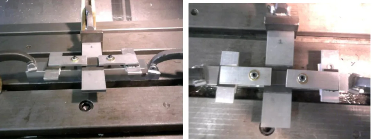
Drilling tests were conducted on a 3-axis machining unit with numerical control. The specimens were drilled with a tungsten carbide bit coated with polycrystalline diamond and having a diameter of 6.35 mm. Several ranges of feed speed and cutting speed were tested to choose the three final drilling configurations. The first produced low Ra, the second medium Ra and the third high Ra (Table 1). A worn tool was obtained after the drilling of a hundred holes, which meant a total drilled length of 450 mm. The flank wear was VB = 0.2 mm and the crater wear was KT = 35 µm. In order to avoid any other type of drilling defects (delaminations at entry and exit), the specimens were clamped with wood plates at both sides
(Fig. 1 and Table 1). Then the overall dimensions and the absence of local burning and delamination were checked. These defects are known to be critical for the mechanical resistance of composite assemblies. This was the only condition imposed in this study. It was thus possible to focus only on the wall defects.
Two types of hole inspections were used. First, a qualitative analysis of the defects was performed using SEM observations on half holes. However, it was impossible to perfectly determine the extent of defects, especially their depths, from these photos. Therefore, to complete the study, drilled specimens produced using two drilling configurations were polished, beginning on their top surface, in order to identify the type of drilling defect around the hole, and progressing into the thickness for each layer of the laminate and for two drilling configurations. Fig.2 shows the method used for polishing the surface. The polishing was done very carefully to avoid creating supplementary defects. To check the technique, a specimen with no hole was polished in the same conditions and no cracks were observed. The specimens were polished in steps of about 250 μm (thickness of a single ply) to observe defects located in each layer.
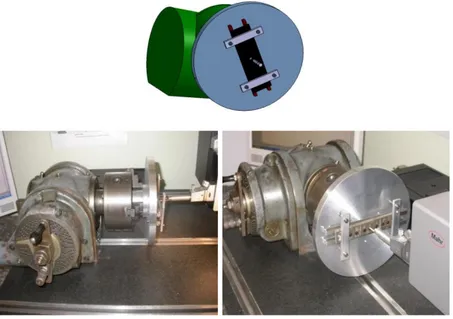
Second, a quantitative analysis was made using conventional roughness measurements. The roughness measurements were performed with a Mahr 3D Roughnessmeter used with the Perthometer concept software. Perthometer concept is a computer-aided measurement station intended for the measurement and analysis of roughness, contours and topography. The probe characteristics are: Inductive Sensor; Measurement extent: +/- 250 µm; Measuring force: 0.7 mN; Tip geometry (DIN ISO): diamond tip; Stylus tip: 2μm/90°; Height of minimal insertion: 4.5 mm; Linearity gap: 1%. A device (Figure 3) was designed to measure the roughness every 1.5° of angle in order to obtain a maximum of information on the hole surface. The tool (Figure 3) was guided on the table and was perpendicular to the probe axis. The components
• One vertical indexing plate to obtain very accurate rotation angle values. The precision was approximately 0.01°.
• One circular plate on which two spacers were screwed to support the specimen. • One centering pin fitted into the central hole of the circular plate.
• Two clamps to hold the specimen on the circular plate.
The specimen was first positioned by means of the spacers so that it was perfectly parallel to the surface of the plate (reference surface on which the assembly rested). It was then centered in the fitting by a pin. The bearing face of the specimen in this assembly was the smooth face obtained after curing. The assembly was positioned (by gauge blocks) in such a way that the stroke of the probe started 0.5 mm from the edge of the specimen. To assess the reproducibility of measurements, five measurements per sample were performed on a set of five samples. The calculated discrepancy of these measurements was less than 6% whatever the samples and the parameter of interest. We deduced that the tool was suitable for making the required measurements.
The cut-off length chosen for all samples was 0.8 mm. The specimens having almost isotropic stacking were palpated over a length of 3.2 mm and those with oriented stacking were palpated over 4 mm. The probing speed was 0.5 mm/s. The diamond tip of the probe was 2 μm in diameter and the angle of the probe tip was 90°. Measurements were carried out every 1.5°, resulting in a total of 240 lines of measurements per hole. This measuring configuration was chosen after a study of the variability of the maximum roughness versus the number of steps on a portion of surface.
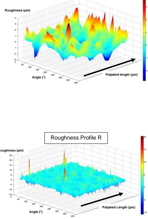
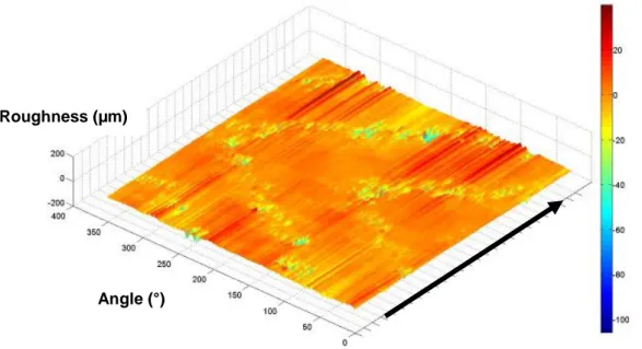
The data were then exported to MATLAB to obtain a roughness map of the hole. A program was written with MATLAB software to obtain a 3D map of a “developed” hole surface
(Figure 4 a-b). The same program calculated (using the ISO standard filters ISO12085, ISO 13565, ISO 4287, ISO 11562) the roughness and waviness parameters associated with the surface (Figure 4b). An example of a pattern obtained for a quasi-isotropic laminate is given in Figure 5.
3)
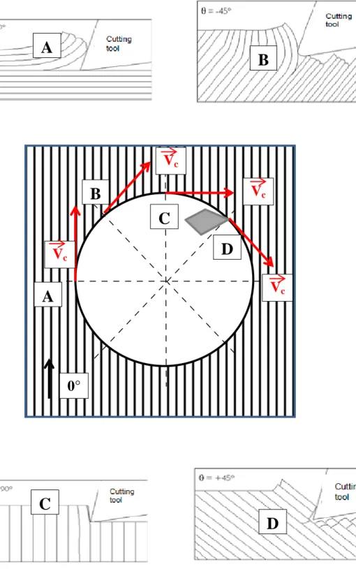
Locations and patterns of the defectsPrevious works [9, 37-38] on orthogonal cutting have shown that the behavior of fibers under the cutting edge depends on the angle they make with the direction of cutting. The most severe drilling defects were caused by tearing out of fibers, and were observed when the fibers were oriented at -45° relative to the direction of cutting. Figure 6 recalls this behavior:
When fibers are at 0° relative to the cutting speed direction (point A), they are subjected to compression and bending. They are "lifted" by the cutting edge (and thus the fibers debond).
When fibers are oriented at 45° relative to the direction of cutting, the fibers are sheared and the surface appears very rough (Point B).
When fibers are oriented at 90° to the direction of cutting (point C), they undergo maximum flexion and then cut cleanly.
When fibers are oriented at –45° to the direction of cutting (Point D), they are subjected to bending and shear. However, this phenomenon is limited by the fiber behind the one in question. When their bending strength limit is reached, fibers break off. Tearing of fiber bundles can then be observed.
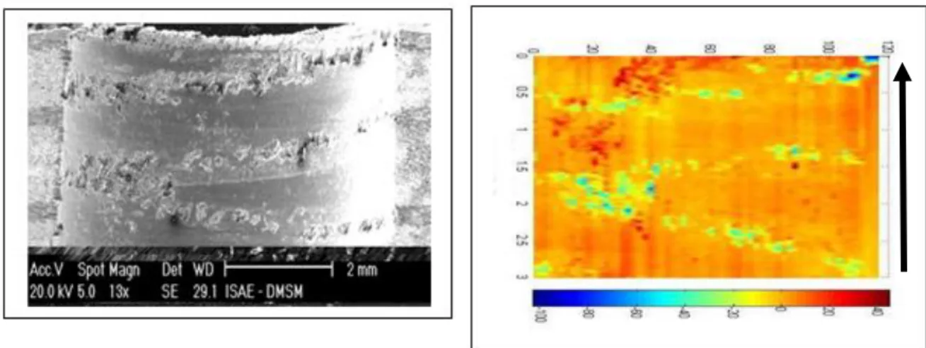
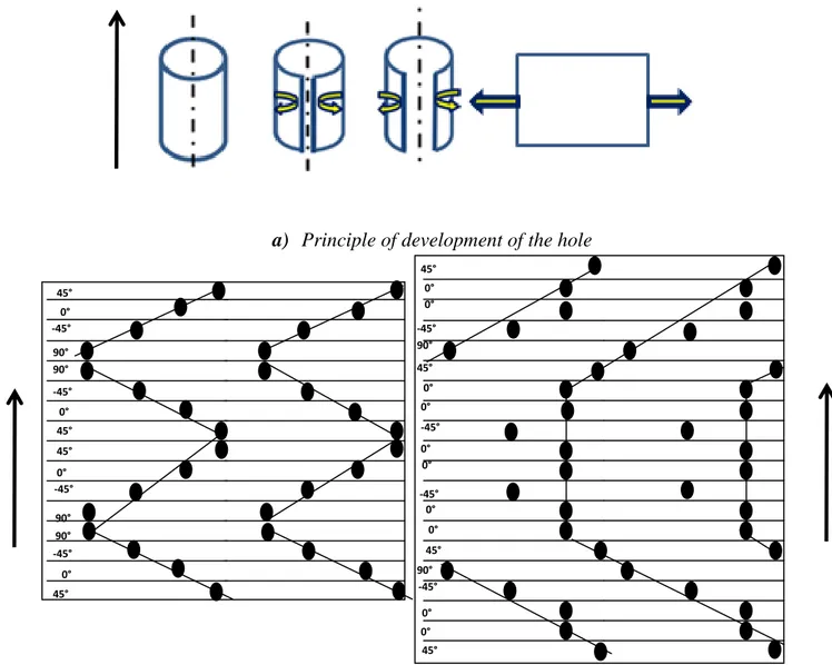
stacking sequence (Fig. 7). For the quasi-isotropic layup, there was a triangular arrangement which was influenced by the shift of + 45° between the plies. For highly oriented laminates, there was a different location in the form of a trapezium due to the large number of 0° plies. A direct comparison of the roughness mapping was also made with SEM observations Qualitative comparisons of defects observed by SEM and roughness mapping are shown in Figure 8. The correlation between these two measurement methods seemed reliable in the sense that the same patterns of defects were observed. This observation suggests that the nature and the location of the defect in the hole wall can be predicted as shown in Figure 9. The diagrams in Figure 9 represent the “theoretical” areas of the largest defects (obtained by considering only the -45° worst defects). These defects were positioned on the developed hole walls. The strong similarity between Figures 7, 8 and 9 shows that the localization of the main defects can be predicted. We note that, unlike the machining of metallic materials, there is no periodicity in the direction of roughness measurement (see Fig.9). Thus a criterion like Ra is not necessarily the most relevant. Moreover, in the practical case where measurement lines are not taken close together for obvious economic reasons, it is possible to obtain very different roughness values along the lines of palpation (usually 4),. A slight shift may generate a large discrepancy in the roughness measurement. This is especially true for highly oriented stacking. Considering the strength, if the location of the largest defects coincides with the highly stressed areas (case of open hole [39, 40] or filled hole [41]), it is likely that they will have an influence on the failure scenario of the part. This link between wall defects and mechanical strength remains to be established, however.
The information noted above is not sufficient to fully characterize the defects. So, a zoom on the defects in the case of a quasi-isotropic laminate is shown in Figure 10. In this figure, the defects predicted in Figure 6 are now visible and can be detailed:
Fig 10 [A]: Tearing located on a 0° ply. This defect is located midway between the edge of the half hole and the hole axis because, at this point, the cutting direction is -45 ° with respect to such fibers.
Fig 10 [B]: Clusters of badly cut fibers located on a 90° ply. This defect is located midway between the edge of the half hole and the hole axis because, at this point, the cutting direction is 45 ° with respect to such fibers.
Fig 10 [C]: Tearing of fibers and matrix located on a ply at -45°. This defect is very close to the axis of the hole because, once again, the direction of cutting is -45° with respect to such fibers. This defect propagates to the adjacent 90° layer.
Fig 10 [D]: Tearing located on a ply at 90°. This tearing occurs midway between the edge of the half-hole and the hole axis for the same reasons as before.
Figures 11 to 14 were obtained after polishing the specimens; they show defects created with two drilling configurations and for each ply direction for comparison.
For the 0° plies, and for good surface finish, the defects are very small, as shown in fig 11b. For bad surface finish, the main drilling defects on the 0° ply appear at -45° relative to the main direction of the fibers and the drill rotation direction as already shown. These defects have the shape of micro-cavities in the ply thickness. Nevertheless, we can also observe the appearance of deeper drilling defects in the main fiber direction, which were not captured by roughness or surface SEM (areas 1 and 2, Figure 11a). These defects are the debonding between fibers and matrix as can be seen on Figure 11c. Under the effect of the drill, the fiber / matrix interfaces undergo high shear stresses and the fibers are thus debonded from each other and protrude from the machined surface. In addition to these defects, and in the immediate surroundings of the hole, deep matrix cracks can be observed in the ply (Fig 11a).
above, a specimen with no hole was polished and no cracks were observed. Thus these cracks were not the result of the polishing process. The polishing process may have increased the cracks but certainly did not create them. The cracks again seem to be related to the drilling process because their density varies with the drilling configuration. The specimen of Figure 11b has few defects but nevertheless has these kinds of cracks in the ply.
The main defects in the 45° layer (Figure 12) were also localized at -45° relative to the main direction of the ply and the drill rotation direction. In the global reference system of the laminate, these defects were located at around 90° relative to the main direction of the laminate. As for the 0° ply, debonding among fibers was observed in the main direction of the ply. Near the area located at -45° relative to the main direction of the layer, fiber pull-out could be seen for both bad and good surface finish. Qualitatively, we see in Figure 12c that the depth of defects was greater for poor finishing, which was to be expected.
The main defects of 90° ply (Figure 13) were located at -45° and 135° relative to the direction of the ply and the drill rotation direction. These defects were mainly pull-out of fiber bundles. Figure 13c shows that the fibers have been pushed following the direction of drill rotation. Some of the fibers have been pulled down while others have bent under the action of the cutting edge but have not been “broken”. The specimen on the right shows good surface finish, but there are still some deep cracks in the ply.
For the last direction (-45°), the main defects were located at -45° and 135° relative to the direction of the ply and the drill rotation direction (Figure 14). These defects had the shape of micro-cavities in the ply thickness. Debonding of fibers can be observed in the main direction of the ply. These fibers protrude from the machined surface. It is also clear that such depth defects, which may eventually affect the mechanical strength, cannot be detected by measuring roughness.
This micrographic analysis confirms the quantitative analysis proposed on the location and the type of defects created during a drilling operation. The mechanisms of occurrence of drilling defects and their nature have been identified. The area with the largest drilling defects is located between two axes (Figure 15):
An axis A, which represents the main direction of the ply.
An axis B, located at -45° relative to the main direction of the ply (axis A)
The most significant drilling defects are located in the area bounded by these two axes. When looking at the holes near the axis A, a debonding of fibers can be seen. Between the two axes, we note:
On the one hand, some fiber bundles that bent under the cutting edge and have not been cut.
On the other hand, the occurrence of micro-cavities linked to the failure of some of these fibers can be observed. These micro-cavities become larger as we look closer to axis B.
The drilling defects on each of the plies cover a relatively large area, which, as these defects are almost symmetric, extends over a zone of two arcs of 45°. Thus, a quarter of each ply may suffer from marked drilling defects.
These original SEM observations provide information on the nature and the location of the drilling defects. They also give some indications on the original roughness profile of drilled laminates, with a very discontinuous and sharp geometric shape of the cuts. This analysis should be useful for defining a specific roughness criterion for composites. In the next section, the size (extent and depth) of these defects is measured with a roughness meter. A
non-usual criterion (the percentage of bearing surface) and the most common criteria, such as Ra, are compared.
4) Roughness analysis
The largest drilling defects have the aspect of micro-cavities. But, as already pointed out, some fibers protrude from the machined surface. Figure 16a shows many red dots corresponding to positive amplitudes of drilling defects. The presence of these points can be explained by microscopic observations. One of the red dots was observed by SEM and is shown in Figure 16b. Fibers are clearly above the surface of the hole. Some fibers fell at the cutting edge in the drilling operation and were badly cut, protruding beyond the machined surface. This defect has already been identified by Ghidossi [36]. It occurs when the fibers are oriented at 0° with respect to the direction of cutting. However, in practice, this defect is not important because the fibers fold and do not carry the bearing forces of a bolt. For this reason, the total area filled by these drilling defects was assessed because, during the contact between the bolt and the hole wall, this area does not bear the bolt. The bearing surface is then the total surface of the hole wall minus the surface area occupied by micro-cavities. This criterion is important because it defines the percentage of the area of the hole wall that is in contact with the bolt. It represents a version of the damaged surface criterion proposed by Ghidossi [36] and extends over the entire hole. It is also defined in the ISO 13565-2, ISO 13565-3, and ISO 12085 standards (bearing length) and ISO 25178 for the surface. It was originally created to analyze the capacity of a bearing surface to retain oil locally for lubrication. Figure 17 represents the methodology for calculating the criterion of bearing surface.
To calculate the percentage of bearing surface, the data collected by the roughnessmeter and exported to MATLAB were re-processed. Initially these data were presented in the form of a matrix where the number of columns corresponded to the number of lines of measurement (so 240 columns). The number of rows of the matrix corresponded to the measured thickness (3.2 mm for the quasi-isotropic laminate and 4 mm for the oriented laminate). Since the dot frequency was 2 points every 0.5 microns, 6400 lines were obtained for the quasi-isotropic laminate and 8000 lines for the oriented one. To achieve the plane map presented above, MATLAB carried out linear interpolation between columns. To calculate the percentage of bearing surface, the rows of the matrix were drawn one by one in a cylindrical coordinate system. The steps below give the details of the calculation:
Initially, a cylinder of diameter 6.35 mm was drawn, which had a height equal to the thickness measured (3.2 or 4 mm). This cylinder was considered to be the arithmetic average of the profile line. The mean line of a profile was the line between the profile’s peaks and hollows.
Secondly, a roughness envelope was created around the 6.35-mm-diameter cylinder. Then, all positive values of the amplitude of this profile were considered as peaks of the profile and all negative values of amplitude were considered as hollows of the profile.
Figure 18 shows an example of hole wall mapping in a cylindrical coordinate system. Figure 18a represents the total hole wall surface (peaks and micro-cavities) and Figure 18b represents the bearing surface as described above. These maps can be thought of as the result of taking an impression of the hole wall. Thus the external rough edges of the maps represent the valleys of the profile and the internal rough edges represent the peaks of the profile. The interest of this criterion is that it can be calculated on the entire surface of the hole and also on
several individual areas depending on the type of mechanical loading applied to the specimen. For example, in the case of a bearing test, some authors, e.g. Gohorianu [42], have determined that there is an area in which the bearing stresses are the greatest. This area is located between -45° and +45°around the bearing axis (see Figure 19). It is therefore possible to calculate the bearing surface criterion in an area of interest.
This criterion can also be calculated differently according to the loading case. The final failure of filled (or not) hole compression specimens is initiated in only a small part of the hole wall [39-41]. Presumably, a poor surface in this area could accelerate the initiation and/or propagation of damage in the area. We can therefore calculate the percentage of bearing surface in this area and evaluate its influence on the test results. It is noteworthy that, in the general case, when using the criterion Ra, the averages are taken over the entire surface, which tends to mask the influence of localized defects in initiating zones of failure.
The influence of the drilling parameters (see Table 1) on the roughness criterion Ra is shown in Figure 20 using a classical statistical box and whisker presentation (mustache boxes). The roughness (Ra) was measured for three specimens per drilling configuration. The graph of Figure 20 presents the evolution of the mean of Ra according to the drilling configuration applied (for 3 x 240 measurements). A first point that can be noted is that the roughness (Ra) increases when the feed speed increases. It seems that the Ramax of the specimens of drilling configuration 2 is higher than the Ramax of the specimens of configuration 3. However, the box plots show that, for the specimens of drilling configuration 3, the minimum values of Ra, and 75% of all Ra values, are higher than those of the specimens of drilling configuration 2. This means that the surface finish of the specimens of drilling configuration 3 is generally worse than that of the specimens of configuration 2. A Student’s test was conducted on the three batches of samples presented above in order to determine whether the Ra values of the 3
the probability that a hypothesis is verified. The hypothesis taken in this study was: “the roughness values obtained with the 3 configurations belong to the same population”. If the probability of this hypothesis (p-value) is less than 5%, then the assumption is not verified and the hypothesis is rejected. Otherwise, we can consider that it is true.
Table 2 shows the different p-values. The red values represent the cases where the hypothesis is verified. The specimens of drilling configurations 2 and 3 belong to the same Ra statistical population. The box plots representing the evolution of the percentage of bearing surface for the same specimens are presented in Fig. 22 21 in order to compare these results with those obtained regarding the Ra criterion. It can also be noted that, for the percentage of bearing surface, drilling configurations 1 and 2 give relatively close bearing surfaces, the average difference of percentage of bearing surface between the configurations 1 and 2 being about 3.74%. This difference is 10.74% on average between configurations 1 and 3.
The results according to the percentage of bearing surface differ from those observed with the roughness criterion Ra (Ra max observed around the hole). Regarding Ra, the specimens of configurations 2 and 3 belong to the same population and are different from the Ra values of the specimens of configuration 1. Regarding the percentage of bearing surface, configurations 1 and 2 produce closer surface finishes than configuration 3.
In order to observe the evolution of Ra according to the percentage of bearing surface, a hundred specimens were drilled, covering the three drilling configurations described above. The interest of this approach was to assess whether the roughness evolved with the same trend as the percentage of bearing surface. This could assess the feasibility of correlation between values of percentage of bearing surface and intervals of roughness values. Fig. 22 shows the result of this study. In some cases, the same range of Ra values corresponds to different values of percentage of bearing surface. Moreover, given that the highest values of Ra do not
correspond to the lowest values of percentages of bearing surface, establishing a link between these two criteria will be difficult.
Given that the roughness values also depend on the type of stylus used (the tip angles of the stylus can vary, e.g. 60° or 90°), the values obtained with two types of stylus were compared for the same specimens. Twenty specimens were measured twice, the first time with a stylus of 60° tip angle and the second time with a stylus of 90° tip angle. Figure 23 shows the result for the Ra criterion. We can see that Ra is sensitive to the stylus used. The Ra values measured using the 90° stylus are less than half those measured by the 60° stylus. The results of these measurements regarding the percentage of bearing surface are given in Figure 24. This criterion is less sensitive to stylus change and the maximum drop observed is about 2.78%.
5) Conclusions
In this research, a refined phenomenological analysis of hole wall defects in drilled CFRP laminates was performed. From a quantitative point of view, a usual roughness criterion was compared with a non-standard criterion. The principal drilling defects had the shape of sharp micro-cavities in the ply thickness. These micro-cavities were mainly located at -45° relative to the main direction of the ply and the tool rotation direction. Some other drilling defects, such as fiber debonding, were observed in the main direction of the fibers. Some cracks along the layer axis, initiated at the hole, were also seen. It should be noted that these defects were averaged by the Ra criterion but the mechanical consequences could be very different. In hole bearing for example, the fibers that protrude from the hole are simply crushed while the cavities may serve as starting points for matrix cracking or delamination. It is for this reason that the percentage of bearing surface was proposed for evaluation. This criterion globally describes the area of the hole wall that is in contact with the bolt. A comparison with the
results of Ra measurements showed that these two criteria gave different results. Moreover, there was no correlation between them. It was found that a given range of Ra values did not correspond to the same range of percentage of bearing surface. Moreover, the highest Ra values did not match the lowest values of percentage of bearing surface. This is important because, in determining the influence of the surface on the mechanical strength, the Ra criterion does not necessarily distinguish the populations of specimens correctly. The sensitivity of the two criteria to measurement stylus geometry change was studied. It was noted that the Ra values were sensitive to a change of stylus. The Ra values dropped by more than 50% when a stylus with a larger tip angle was usedbut the percentage of bearing surface was less sensitive. The values dropped by about 2.78% in the worst case. The contact measurement mean for composite surfaces (whatever the stylus geometry), is more suitable as an overall surface criterion than as a localized criterion.
In conclusion, this study raises the question of the analysis and quantification of the quality of holes drilled in composite laminates. The percentage of bearing surface was evaluated in the context of this study and confirmed the inadequacy of Ra. In the authors’ opinion, other types of quality indicators, such as some used to characterize woods (SRsk and SRku) or others that may already exist or remain to be invented, must be evaluated to quantify the machined surface of laminated composites. Finally, the link between relevant indicators of the quality of the surface and the mechanical behavior of the drilled composite structures needs to be established by an exhaustive series of static and fatigue tests.
Acknowledgments
The academic authors thank Airbus Operation S.A.S. for its support, especially Audrey Bénaben, Clément Chirol and Bernard Bourthoumieux.
References
[1] Abrate S. Machining of composite materials. In: Mallick PK (ed.) Composites engineering
handbook. New York, NY: Marcel Dekker, 1997, pp.777–809.
[2] Beral B. Airbus structure and technology – next steps and vision. In: Proceedings of 16th
international conference on composite materials. Kyoto; 2007.
[3] Khashaba UA. Drilling of polymer matrix composite: a review. J. Comp. Mat. 2013;
47(15) :1817-1832
[4] Liu D, Tang Y, Cong WL. A review of mechanical drilling for composite. Comp. Struct.
2012; 9:1265-1279.
[5] Sing AP, Sharma M, Singh I: A review of modeling and control during drilling of fiber reinforced composite. Comp. Part B 2013 ;47:118-125.
[6] Rajakumar IPT, Hariharan P, Vijayaraghavan L. Drilling of carbon fiber reinforced (CFRP) composite: a review. Int. J. Mat. Product Tech. 2012;43(1-4):43-67
[7] Abrao AM, Faria PE, Campos Rubio JC, Reis P, Paulo Davim J: Drilling of fiber reinforced plastics: a review. J. Mat. Process Tech 2007;186:1-7.
[8] Piquet R, Ferret B, Lachaud F, Swider P. Experimental analysis of drilling damage in thin carbon/epoxy plate using special drills. Comp. Part A 2000;31:1107–15.
[9] Lachaud F, Piquet R, Collombet F, Surcin L: Drilling of composite Structures. Comp.
Struct. 2001 ;52(3-4):511-516.
[10] Wong TL, Wu SM, Croy GM. An analysis of delamination in drilling composite materials. In: 14th National SAMPE technology conference. Atlanta, GA, USA; 1982. p. 471–
[11] Stone R, Krishnamurthy K. A neural network thrust force controller to minimize delamination during drilling of graphite-epoxy laminates. Int. J. Mach. Tools Manuf.
1996;36:985–1003.
[12] Hocheng H. The path towards delamination-free drilling of composite materials. J. Mat.
Process Tech 2005;167(2-3): 251-264.
[13] Krishnaraj V., Prabukarthi A., Ramanathan A., Elanghovan N., Kumar MS, Zitoune R., Davim JP. Optimization of machining parameters at high speed drilling of carbon fiber reinforced plastic (CFRP) laminates. Comp. Part B 2012:43(4);1791-1799
[14] Zitoune R., Krishnaraj V., Almabouacif S., Collombet F., Sima M., Jolin A.. Influence of machining parameters and new nano-coated tool on drilling performance of CFRP/Aluminium sandwich. Comp. Part B 2012:43(3);1480-1488
[15] Shyha IS, Soo SL, Aspinwall D, Bradley S. Effect of laminate configuration and feed rate on cutting performance when drilling holes in carbon fibre reinforced plastic composites. J.
Mat. Process Tech. 2010;210:1023–34.
[16] Durao LMP, Goncalves DJS, Trvares JMRS, de Albuquerque VHC, Vieira AA, Marques AT. Drilling tool geometry evaluation for reinforced composite laminates. Comp. Struct.
2010;92:1545–50.
[17] Lopez De Lacalle LN, Lamikiz A, Campa FJ, Valdivielso AFdz, Etxeberria I. Design and test of multi-tooth tool for CFRP milling. J. Comp. Mat. 2009;43:3275–90.
[18] Rahmé P, Landon Y, Lachaud F, Piquet R, Lagarrigue P. Analytical models of composite material drilling. Int. J. Adv. Manuf. Tech. 2011;52(5) :609-617.
[19] Zitoune R. and Collombet F. Numerical prediction of the thrust force responsible of delamination during the drilling of the long-fibre composite structures. Comp. Part A 2007;
38: 858–866.
[20] Upadhyay PC, Lyons JS. On the evaluation of critical thrust for delamination-free drilling of composite laminates. J. Reinf. Plastics Comp. 1999;18:1287–1303.
[21] Enemuoh EU, El Gizawy AS, Okafor AC. An approach for development of damage-free drilling of carbon fiber reinforced thermosets. Int J. Mach. Tools Manuf. 2001;41:1795–1814.
[22] Mathew J, Ramakrishnan N, Naik NK. Trepanning on unidirectional composites: delamination studies. Composites Part A 1999;30:951–959.
[23] Chen WC. Some experimental investigations in the drilling of carbon fiber reinforced plastic composite laminates. Int J. Mach. Tools Manuf. 1997;37(8):1097–1108.
[24] Davim P, Campos Rubio J, Abrão AM. A novel approach based on digital image analysis to evaluate the delamination factor after drilling composite laminates. Comp Sci. Tech.
2007 ;67(9) :936-45).
[25] Abrão, A.M. ; Campos Rubio, J. C. ; Faria, P. E. De ; Davim, J. P. . Drilling technology. In: J. Paulo Davim. (Org.). Machining composite materials. London: ISTE - Wiley, 2009, v. , p. 113-165 (ISBN 978-1-84821-170-4).
[26] Haddad M, Zitoune R, Eyma F, Castanié B. Machinability and surface quality during high speed trimming of multi directional CFRP. Int. J. Mach. Mach. Mat. 2013; 13(2/3):
[27] Squires CA, Netting KH, Chambers AR, Understanding the factors affecting the compressive testing of unidirectional carbon fibre composites. Comp. Part B 2007;(38) :481–
487.
[28] Pihtili H, Canpolat N. Investigation of different reinforced composite materials for surface roughness and capacity of being drilled. J. Comp. Mat. 2009;43:2071-2080.
[29] Hocheng H, Tsao CC. Evaluation of thrust force and surface roughness in drilling composite material using Taguchi analysis and neural network. J. Mat. Proc. Tech.
2008;203:342-348.
[30] Arola D, McCain ML. Surface texture and the stress concentration factor for FRP Components with holes. J. Comp. Mat. 2003;37(16):1439-1460.
[31] PERSSON, E.; ERIKSSON, I. et ZACKRISSON, L. “Effects of hole machining defects on strength and fatigue life of composite laminates”, Comp. Part A 1997;28:141-151
[32] U.A. Khashaba, I.A. El-Sonbaty, A.I. Selmy, A.A. Megahed. Machinability analysis in drilling woven GFR/epoxy composites: Part I – Effect of machining parameters. Comp. Part A 2010;41:391–400
[33] U.A. Khashaba, I.A. El-Sonbaty, A.I. Selmy, A.A. Megahed Machinability analysis in drilling woven GFR/epoxy composites: Part II – Effect of drill wear Comp. Part A 2010;41:1130-1137
[34] M. Saleem, L. Toubal, R. Zitoune and H. Bougherara. Investigating the effect of machining processes on the mechanical behaviour of composite plates with circular holes. Composites Part A: Applied Science and Manufacturing. 55, 169–177. 2013
[35] Shyha IS, Soo SL , Aspinwall DK, Bradley S, Perry R, Harden P, Dawson S. Hole quality assessment following drilling of metallic-composite stacks. Int J. Mach. Tools Manuf.
2011;51(7–8):569–578.
[36] Ghidossi P, El Mansori M, Pierron F. Influence of specimen preparation by machining on the failure of polymer matrix off-axis tensile coupons. Comp Sci. Tech. 2006:66(11–
12);1857–1872.
[37] Koenig W, Grass P. Quality definition and assessment in drilling of fibre reinforced thermosets. Annals of the C.I.R.P 1989;38:119-124.
[38] Zitoune R., Collombet F. Lachaud F., Piquet R., Pasquet P. Experiment–calculation comparison of the cutting conditions representative of the long fiber composite drilling phase.
Comp. Sci. Tech. 2005; 65: 455–466.
[39] Hallett S.R., Green B.G., Jiang W-K., Kin Hei Cheung K. I., Michael R. Wisnom M. R. The open hole tensile test: a challenge for virtual testing of composites. Int. J. Fract. 2009:
158;169–181
[40] Prabhakar P, Waas A. M. A novel continuum-decohesive finite element for modeling in-plane fracture in fiber reinforced composites. Comp. Sci. Tech. 2013: 83; 1–10
[41] Castanié B, Crézé S, Risse L, Barrau JJ, Lachaud F. Experimental analysis of failures in filled hole compression tests of carbon/epoxy laminate. Comp. Struct. 2010 :92(5) ;1192-99
[42] Gohorianu G. Interaction entre les défauts d’usinage et la tenue en matage d’assemblages boulonnés en Carbone/Epoxy. PhD thesis, Université Paul Sabatier, Toulouse, 2008 .
Fig. 1: Drilling device.
Fig. 2: Method for polishing specimens.
45° ply 0° ply 90° ply -45° ply Polishing direction Polishing pad
a) “Developed” hole surface
Angle (°) Palpated Length (µm)
Roughness (µm)
Primary Profile P
Waviness Profile W
b) The three principal normalized roughness profiles : Primary, Waviness and Roughness
(µm)
Fig. 4. Maps obtained with roughness measurements
Angle (°) Angle (°) Palpated length (µm) Palpated Length (µm) Roughness (µm) Roughness (µm) Roughness Profile R
Fig. 5. Example of the primary profile of a hole with “V” pattern of defects
Roughness (µm)
Fig. 6: Behavior of fibers under the cutting edge according to their orientation relative to the cutting speed direction.
A
V
cV
cV
cA
B
C
D
V
c0°
C
B
D
Fig. 7: Drilling defect locations for the two stacking sequences: Quasi-isotropic laminate (a) and Oriented laminate (b) .
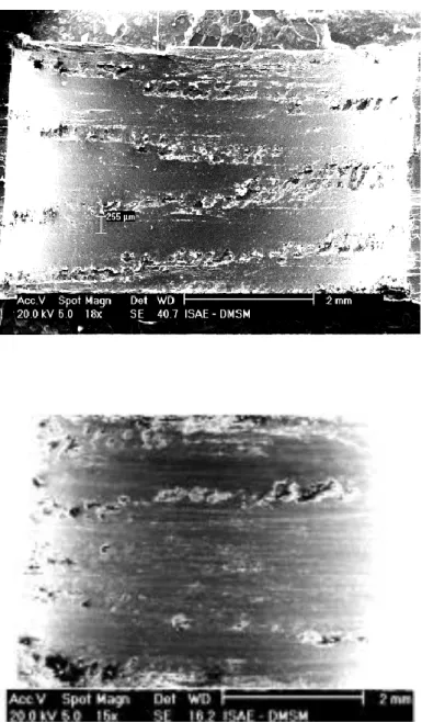
Fig. 8. Comparison between micrographic observations and roughness maps (quasi-isotropic stacking).
a) Principle of development of the hole
a) Quasi-isotropic laminate c) Oriented laminate
Fig. 9: Drilling defect patterns predicted for the two stacking sequences by considering the worst defects. C V C V C V C V C V C V C V C V C V C V C V C V C V C V C V C V 45° -45° 0° 90° 0° 45° 0° -45° 90° 0° -45° 0° 0° 0° 45° 0° -45° 0° 0° 45° 0° 90° 0° 90° 0° 45° 45° 45° 45° 0° 90° 90° -45° -45° -45° -45° Direction of palpation
Figure 10. Microscopic views of largest wall defects (drilling configuration 3).
A B C D Hole Axis Half-hole boundaries Axis
0° layer
a) Bad surface finish b) Good surface finish
Fig. 11: Drilling defects on the 0° ply. (a): drilling configuration (3); (b): drilling configuration (1)
0°
0° 1
Drill rotation direction
2
1
Debonding of fibers
45° layer
Fig. 12: Drilling defects on the 45° ply. (a): drilling configuration (3); (b): drilling configuration (1)
c. Magnification of the drilling defects
Drill rotation direction
a. Bad surface finish
45° 45°
b. Good surface finish
c.
Micro-cavities
90° layer
Fig. 13. Drilling defects on the 90° ply. (a): drilling configuration (3); (b): drilling configuration (1)
c. Magnification of the drilling defects
a. Bad surface finish b. Good surface finish
90° 90°
1
1
Drill rotation direction
Micro-cavities
Crack in the main direction of the ply
-45° layer
Figure 14: Drilling defects on the -45° ply. (a): drilling configuration (3); (b): drilling configuration (1)
Drill rotation direction
c. Magnification of the drilling defects
a. Bad surface finish b. Good surface finish
1 -45° -45° 1 Micro-cavities Debonding of fibers 2000 µm 2000 µm
Fig. 15. Location of drilling defects
Arc of 45 ° with numerous drilling defects
0° Axis B
Fig. 16. Analysis of protruding fibres through roughness mapping and micrographic view.
(a) Mapping made by the roughnessmeter
(b) Micrographic view of a red dot
Fig. 17: Method for calculating the percentage of bearing surface.
Median line (circle of diameter 6.35)
Primary profile mesuré Valley of the profile =
micro-cavities Peak of the
profile
% bearing surface area= 1-(surface area of micro-cavities / theoretical surface)
Fig. 18: Representation of a hole wall surface and the bearing surface of the same hole
Hole radius = 3175µm Values < hole radius= peaks of the
profile
Values > hole radius= valleys
of the profile 0
(a) Entire hole surface (peak +valley)
(b) Bearing surface (valley of the profile)
Fig. 19 : Example of localized roughness surface measurement linked to a loading case.
Fig. 20: Influence of the drilling conditions on Ra
Real bearing area
-45° +45°
0°: Loading direction
Fig. 23: Influence of stylus tip geometry on Ra values
Table 1: Drilling configurations
Drilling configurations N (rpm) f (mm/flute) Tool state Dust aspiration Lubrication CFRP Backing plate
1 : Good surface texture 4800 0.02 Not worn Yes No With wood plate at
entry and exit of the drill bit
2 : Medium surface
texture 4800 0.1 worn Yes No
3 : Bad surface texture 500 0.35 worn Yes No
Table 2: p-value for the roughness criterion Ra
Configuration 1 Configuration 2 Configuration 3
Configuration 1 8.91E-22 1.33E-34
Configuration 2 8.91E-22 0.4