HAL Id: hal-00739604
https://hal.archives-ouvertes.fr/hal-00739604
Submitted on 20 Jun 2017
HAL is a multi-disciplinary open access
archive for the deposit and dissemination of
sci-entific research documents, whether they are
pub-lished or not. The documents may come from
teaching and research institutions in France or
abroad, or from public or private research centers.
L’archive ouverte pluridisciplinaire HAL, est
destinée au dépôt et à la diffusion de documents
scientifiques de niveau recherche, publiés ou non,
émanant des établissements d’enseignement et de
recherche français ou étrangers, des laboratoires
publics ou privés.
Distributed under a Creative Commons Attribution| 4.0 International License
Simulators based on Model Transformations: The IMS
Case Study
Iyas Alloush, Vanea Chiprianov, Yvon Kermarrec, Siegfried Rouvrais
To cite this version:
Iyas Alloush, Vanea Chiprianov, Yvon Kermarrec, Siegfried Rouvrais. Linking Telecom Service
High-level Abstract Models to Simulators based on Model Transformations: The IMS Case Study. 18th
European Conference on Information and Communications Technologies (EUNICE), Aug 2012,
Bu-dapest, Hungary. pp.100-111, �10.1007/978-3-642-32808-4_10�. �hal-00739604�
Models to Simulators based on Model
Transformations: The IMS Case Study
Iyas Alloush1,2
, Vanea Chiprianov1,2
, Yvon Kermarrec1,2
, and Siegfried Rouvrais1,3
1: Telecom Bretagne, Institut Mines-Telecom, Universit´e europ´eenne de Bretagne Technopole Brest Iroise, CS 83818 29238, Brest Cedex 3, France
2: UMR CNRS 6285 Lab-STICC 3: IRISA
Abstract. Telecommunication services are widespread and subject to-day to tensions on a competitive market. Telecommunication service de-sign is more and more software oriented. To reduce time to market and cost of services, a service designer better need to simulate and evaluate his design earlier. The approach proposed in this paper is to reduce the abstraction gap between modeling and simulation phases using model transformation. But manual transformations are so far time consuming and error prone. As a trustworthy solution, model based techniques and associated transformations permit to systematically link service mod-els with simulation phase before realization. We thus propose as a first contribution a meta-model dedicated to concepts of IP Multimedia Sub-system core network as a case study. Our meta-model constrains and defines such network entities to be used in the code generation, which is our second contribution. The implementation of a video conference service permits to illustrate our workbench.
Keywords: Software Engineering, Model Driven Engineering, Model Transformation, Telecommunication Services, Meta Model, Domain Spe-cific Modeling Languages, Code Generation, Simulation, OPNET, IMS
1
Introduction
During the recent years, telecommunication economy has been expanding rapidly, due to the increasing numbers of network and Internet users, and huge expansion of the available bandwidth. Clients of an operator require high quality of service and easy access (in terms of configuration use, interface,...) with reasonable fees. They can nowadays pay their bills, buy goods, download/upload files, chat and join video conferences. . . using their mobile phones or other types of terminals. It is important for telecommunication service providers to design and implement such new telecom services in an efficient way before realization, so they can enter the service market more rapidly, trustworthy, and successfully.
Designing a new service is still a daunting task: from an early informal ex-pression of user’s needs, the provider should design, develop, test,... and integrate it in a platform/environment. For the design phase, we can consider a high level abstraction of the service, which makes it possible for the designer to cope with the complexity. In this proposal, our purpose is to assist this designer, as domain experts having finally to combine a high level abstraction with a low level one, e.g. network components and connectors. The low level expertise make it pos-sible to design, plan, connect, and configure several equipments such as routers and switches, while the high level provides a higher abstraction which provides to each component an interface, a behavior, features and properties.... The issue is to reconcile both levels.
A recent PhD dissertation explored a new Domain Specific Modeling Lan-guage (DSML) [10], where designers can design new telecom service models using a friendly and graphical user interface including high level of abstraction entities and relationships. The proposed Domain Specific Modeling Language (DSML ex-tensions on ArchiMate) respects a multi-layer framework called the Enterprise Architecture (EA) from the Open Group [24].This architecture is composed of three main layers (Business, Application, and Technology) that differ in the abstraction level and provide complementary view points. The associated tool produces models that need to be implemented to provide the service function analysis. Nevertheless, models contain information that can be used to simulate behavior or check properties, e.g. check message-flow to discover eventual design errors. Once a model is designed, the next step is to verify this model by simu-lation which can give early feedbacks on the service. These feedbacks will make it possible to detect and identify flows and errors in the design, which are to be corrected. With this approach, deployment cost and time could ultimately be reduced. Our main goal is to establish a link between models and suitable well known simulators, depending on the domain.
Telecommunication services is the domain of interest in this paper. The afore-mentioned approach is tested using network traffic measurement reports to eval-uate the behavior of service models produced by a defined DSML, then to make modifications to the models accordingly. The Core Network used for the service simulation process as a case study is the well known IP Multimedia Subsystem (IMS). Our first contribution in this paper is in producing a meta-model that defines the IMS core network in the technology layer of the EA [11]. This pro-vides the link between the other higher level layers and the network level, as it includes the IMS components and the most important functions needed for implementing a new telecom service. A designer will use the DSML to produce his telecom service models that conform to the proposed meta-model. From this model the designer can obtain the simulation scenario as a configuration file specific for a network simulator. This is achieved by using model transformation (code generation) step which is our second contribution.
In Section 2, we highlight the benefits of models and metamodeling ap-proaches for telecom services, and we describe why model driven engineering approach is a proper approach. Also we indicate briefly to the concepts of
Archi-Mate and Enterprise Architecture and the relation between them. In Section 3, we present briefly the concepts of the IMS and its basic protocol, to show why it is a potential suitable solution for new service implementation. In Section 4, we present our first contribution in designing an IMS dedicated meta-model, and how to use it so as to represent a service using networking simulators which is our second contribution. Such simulations make it possible to analyze and test service behaviors and message-flows so a designer can make the modifications on his early design whenever necessary. In Section 5, we illustrate how models can be used and applied in the context of a video conference service. Obviously, the IMS core network is used as our framework architecture.
2
Development with models in Model Driven Engineering
2.1 Model Driven Engineering
Definition 1 (Model[20]). is a simplified representation or an abstract de-scription of a part of the world named the system.
The Meta-Model (MM)”defines by itself a language for describing a Specific Domain of interest”[8]. The motivation from designing a MM is the large number of possible domain-specific models that conform to it.
Definition 2 (Model Driven Engineering (MDE)[10]). is a software de-velopment method which focuses on creating and exploiting domain models. It allows the exploitation of models to simulate, estimate, understand, communi-cate and produce code.
In MDE, models are considered as the unifying concept in IT engineering, and they can appear in different forms (λ-models) due to the specific needs [18]. Mod-els are useful, as they are powerful for documenting, decomposing complexity of systems. They are known as the initial design diagrams that are used to com-municate ideas between developers [18] as they have the capability of describing the system in terms of entities, properties, functions, and relationships.
Model Driven Engineering has been investigated with success in software en-gineering [16,22] and new techniques have been developed such as model trans-formation [14]. Numerous support tools have been developed these last years and Eclipse plays a central role in IT domain nowadays.
Eclipse forms a complete development environment as it provides tools for modeling, such as Meta-tools (Eclipse Modeling Framework), editors, compil-ers,. . . . EMF supports graphical editors to deal with different types of models such as ecore files. Eclipse also contains a lot of model transformation languages such as XPAND [15], ATL [2], QvT [21]. The concept behind the meta-tool is that it allows specification and generation of another tool [13,12]. We see that eclipse forms a complete environment that supports the Model Driven Engineer-ing approach.
Fig. 1.EA modeling framework and relation with ArchiMate[23]
2.2 Enterprise Architecture and ArchiMate
Enterprise Architecture (EA)[17]:”is an instrument to articulate an enter-prise’s future direction, while also serving as a coordination and steering mech-anism toward the actual transformation of the enterprise”.
ArchiMate[1]: ”is an open and independent enterprise architecture modeling language to support the description, analysis and visualization of architecture within and across business domains in an unambiguous way”.
Enterprise Architecture specifies how the services and products are offered by processes and applications. In order to manage complexity of service design, EA (Fig 1) decomposes an Enterprise into two dimensions, the aspect dimension and the layer one. The layer dimension purpose is to separate between speci-fications of designers into different layers of abstraction. The aspect dimension provides an aspect conceptualization of an enterprise. Both dimensions divide the framework to smaller cubes, each cube forms a viewpoint. ArchiMate (Fig 1) offers a modeling language to design the architecture.
3
IP Multimedia Subsystem (IMS)
3.1 Definition and reasons of choice
Definition 3 (IP Multimedia Subsystem (IMS) [4]). is an architectural framework for delivering Internet Protocol (IP) multimedia services
IP multimedia Subsystem (Fig.2) can be integrated with Internet, as it handles all communications in Packet Domain. Also it plays an important mediation role which allows the operators to provide common services between 3G, Wi-Fi and other wired IP networks like Digital Subscriber Line (DSL). Those features make IMS a suitable core network to rely on when designing telecom services that may
Fig. 2.3GPP IMS architecture (IP Multimedia Core Network Subsystem)[9]
work on different types of devices (Mobile, PDA, Laptop,. . . ). Telecom Services are becoming more and more software based. IMS gives a solution for such a revolution due to its Application Server (AS) component [9], and the structure of the signaling protocol used to initialize the sessions (SIP protocol) which is an application layer protocol [6].
3.1.1 Session Initiation Protocol (SIP) [6]: is an IETF-defined signal-ing protocol widely used for controllsignal-ing communication sessions such as voice and video calls over Internet Protocol (IP). The protocol can be used for cre-ating, modifying and terminating two-party (unicast) or multiparty (multicast) sessions. Sessions may consist of one or several media streams.
SIP is used in IMS as the basic signaling protocol to create sessions and manage them, as it is based on the structure of the wide used Internet protocol HTTP. SIP service developers can use all the service frameworks developed for HTTP, such as CGI (Common Gateway Interface) and Java servlets [9]. SIP does not differentiate the User-to-Network Interface (UNI) from a Network-to-Network Interface (NNI), but it works as end-to-end.
In NS-2 simulator [19], there were efforts to simulate the SIP protocol and integrate it to IMS core network. For this context, we compared between the capabilities of NS-2 and the capabilities of OPNET simulator. We found that OPNET [5] was more adequate than NS-2 because OPNET provides higher level of abstraction by creating customized higher level applications. In OPNET, one can define his new customized application using the task configuration entity provided by OPNET.
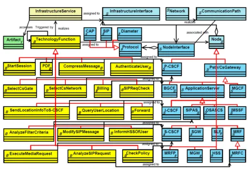
Fig. 3.Our proposed IMS meta-model (Technology Layer of EA)
4
A meta-model for IMS and code generation process
4.1 IMS meta-model proposal
We have selected Enterprise Architecture (EA)[23] to present meta-model in a way that fits well the expertise of Network Architect. We have selected the Archi-Mate standard to model the IMS Architecture. Aspects native to ArchiArchi-Mate are derived from [24] and [23]. In (Fig 3), the entities that are tagged with (S char-acter) are the structural ones, entities that are tagged with (B charchar-acter) are the behavioral ones, while the Information entities are tagged with (i character). One can link between the colors of the entities in (Fig 3) to those in (Fig 1).
4.1.1 Meta-model design justification When building a meta-model for IMS, we have numerous solutions in joining the entities and their relations. We have proposed a meta-model that appears in (Fig.3). We provide below a few explanations and rationale: The MM is divided into 3 sections from aspect point of view, the artifact entity on the left ”informational aspect”, the Behavioral entities in the middle, and the structural entities on the right. The Infrastruc-tureInterface and the InfrastructureService entities are positioned on the top of the MM, this shows the separation between the structural aspect and the behavioral one. The structural aspect represents the hardware part, while the behavioral one represents the software part of IMS core network. But there is also a usage relationship between them, where the InfrastructureService is assigned
to the InfrastructureInterface. For example, the PDF (Policy Decision Function) is assigned to the P-CSCF node type[9]. The InfrastructureService accesses the Artifact entity. This is logical, as software functions need sometimes input of data to perform their tasks. In the list below, we present the rest of rationales grouped by their aspects:
– Structural Entities
• The connection between the NodeInterface entity and the protocol entity is the aggregation relationship. The NodeInterface should contain at least one protocol to use to communicate with other entities.
• The connection between the NodeInterface entity and the Communica-tionPath entity is an association relationship. This means that an inter-face should have a physical communication media to send/receive data. ”NodeInterface deals with software and the hardware concepts”. • Every node entity has an aggregation relationship with the NodeInterface
entity. The source entity can have a group of the target entities, which are initiated and controlled by the source entity. For example: HSS has many interfaces with other nodes due to its central role. So it has (Fig.2) Cx interfaces with the S-CSCF and I-CSCF, and Si interface with IM-SSF,. . .
• A protocol entity can be: a Diameter, CAP, or SIP (inheritance relation-ship between the Protocol entity and the mentioned protocol types). But there are many other protocols used in IMS and we just included some of them. One can extend the Meta-Model (Fig.3) and add new protocols. • The CommunicationPath represents the communication route that may
pass through several non-IMS nodes such as routers.
• A network entity is connected to the CommunicationPath entity through realizes relationship, so the CommunicationPath is implemented by a Network.
– Behavioral Entities
• Every behavioral entity inherits its specifications from the Technology-Function entity. This relation provides the ability of defining common specifications for all behavioral entities such as the triggering relation-ship that is targeted from the TechnologyFunction to itself. For example, the StartSession function can call the PDF (Policy Decision Function) as they are both TechnologyFunctions.
• Every behavioral entity is connected to a node entity through an assign-ment relationship, so a node cannot use a behavior that is not assigned to it. A node function could be one or sequence of behaviors that are assigned to that node, triggering relationship provides that sequence. This meta-model (Fig.3) contains the types of the entities and relationship def-initions that will constrain the next step when a new service model will be fed to the code-generation engine. For example, every entity in the service model of type that is not defined in the meta-model will be rejected.
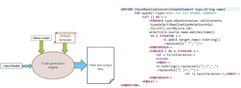
Fig. 4. Code generation work-flow for model execution and simulation (using Eclipse software environment)
Fig. 5.XPAND code for checking the real-ization relationship that is included in the service model
4.2 Code Generation Engine
Our objective is to provide a link between the service model and the simulators. After providing the meta-model in the previous section, we defined the con-straints, entities, and relationships of the service model using the DSML [11]. Now we need to configure the network simulator automatically to present the same network and functionality design of the service model. In model driven en-gineering, model transformation provides an adequate solution for our objective. Model Transformation has many types [20], but what we need for our objective is the Model to Text (M2T) type. After comparing between ATL, and XPAND we found that the XPAND is more adequate language for our objective as it is a M2T model transformation language. Now we can generate text files in a format that is targeted to the specifications of the network simulator.
4.2.1 XPAND Model Transformation Language [3], is a statically-typed template language featuring polymorphic template invocation, aspect oriented programming, functional extensions, a flexible type system abstraction, model transformation and validation. Includes an editor which provides features like syntax coloring, error highlighting, navigation, refactoring and code comple-tion.To start the code generation process presented in the (Fig.4) we need the two models: Meta-Model that defines the entities of the service model and the relationships between them, and the Service Model that conforms to the Meta-Model and describes the service structural and behavioral entities. Also we need the XPAND template. Fig.5 shows an example of checking realization relation-ships. One can see that XPAND code contains iterations, lists, and conditions.
5
Video Conference Example using IMS
Video Conference[7]: is a set of telecommunication technologies which allow two or more locations to communicate by simultaneous two-way video and audio
Fig. 6.IMS Conference joining message flow chart [9]
transmissions. It has also been called ’visual collaboration’ and is a type of groupware. The Meta-model is the same which proposed in (Fig.3), the service model was divided into two models: structural model, and behavioral model due to their large sizes. The service models that includes the specifications of the Joining Conference Case study are presented in[11], where the service design contains models for the 3 ArchiMate layers; not only the technology layer.
5.1 Behavioral model to Task configuration in OPNET
In OPNET simulator, we have the customized application feature. The appli-cation events are defined in the task configuration entity in the same scenario configuration file that contains the network structural description. The idea is to transform the behavioral service model into events that are configured auto-matically in the task configuration table inside OPNET scenario. The behavioral service model described in [13] is following the flow chart in (Fig.6) [9]. After running the scenario (that is generated by the code generation engine using Eclipse) in OPNET simulator, we can trace the message flow chart described in (Fig.6) on the 2D-Animation screen (OPNET). The succession in calling be-haviors, there is a relationship called (Triggering Relationship). The triggering relationship is defined in the meta-model (Fig.3).
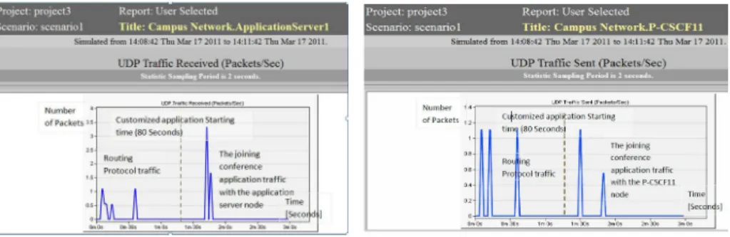
Fig. 7.UDP traffic received by Applica-tion Server in the Joining conference sce-nario; generated using OPNET
Fig. 8. UDP Traffic sent by P-CSCF11 node in the joining conference scenario, gen-erated using OPNET
5.2 Measurement Analysis
We are going to take two charts from the measurement reports produced by OPNET, one for the Application Server and the other is for the P-CSCF and analyze them. In the figure (Fig.7), the chart presents the traffic received by the Application Server node (AS). There are two traffic areas that are separated by the dashed line (“the starting time of our application is set to start after 80 seconds”), the traffic to the left of that line is a routing protocol one, while the traffic shown to the right is the joining conference application traffic. In the figure (Fig.8), the P-CSCF node starts its packet exchange before the applica-tion server; P-CSCF applicaapplica-tion-traffic starts at the time “1,30 minutes”. The separation period between the peaks in (Fig.7) is smaller than the corresponding one in the (Fig.8). This is because there are 4 nodes that need to finish their roles before returning the (Session Progress) SIP message back. The case is dif-ferent when we talk about the Application Server, which should negotiate for the session setup with the MRFP and S-CSCF as presented in (Fig.6). After the session resources are reserved, AS sends the SIP message containing the session description (Session Progress) back to the user agent through the P-CSCF. That is why the time period between the peaks is narrow in the AS chart comparing to that in the P-CSCF.
6
Conclusion and Future work
In this paper, we have presented our results on modeling telecom services based on a Model Driven Engineering approach. Model based techniques and transfor-mations are powerful ways to build and execute a model with a link to network simulators. Simulation can further provide insightful results that may be used to modify models. We have selected IP Multimedia Subsystem (IMS) as the archi-tectural framework of the modeling platform due to its wide usage in the domain. Selecting IMS for our technology layer gives the feature of various IP applications selection possibilities, that a designer could use in building his service-functions.
Our first main contribution is (1) a meta-model to describe IMS. Using Meta-models in the design cycle gives the design Meta-models re-usability, variability, and commonality, and permits the configuration of each specific application to be se-lected according to the domain specifications. With this meta-model, integrated in the Eclipse development environment, we have been able to provide our sec-ond contribution: to (2) represent IMS within network simulators and perform checks/analysis to the designed service (e.g. videoconferencing). With the video conference example, we have shown how, using the IMS meta-model and code generation, that it is possible to generate configuration files for various simula-tors and execute them. Through this, it is thus possible to execute more or less a model. For the future, on the one hand, the authors propose to investigate how the mentioned simulation results can be fed into the various model directly, so as to assist designers during the various phases, and especially after potential reconfigurations and supporting non regression. On the other hand, based on the Model Driven Engineering Techniques, we plan to investigate more deeply how several model transformation could be managed so as to simulate and check higher abstract models on several tools, in which preferable order and at the right time. Almost, a defined tool chain is also susceptible to be acquainted with specific information such as certification levels of tools for trustworthiness.
7
Acknowledgments
The authors acknowledge the support of OPNET in providing their academic edition, which made it possible for them to use and integrate the simulation tools in their transformation chain.
This paper presents a contribution which is a result of a master internship period done by Iyas Alloush and the results were included in the PhD thesis of Vanea Chiprianov[10] under supervision of Yvon Kermarrec and Siegfried Rouvrais.
References
1. Archimate. Wikipedia, http://en.wikipedia.org/wiki/ArchiMate 2. Atlas transformation language, http://www.eclipse.org/atl/ 3. Eclipse modeling, http://www.eclipse.org/modeling/
4. Ip multimedia subsystem definition, http://en.wikipedia.org/wiki/IP_ Multimedia_Subsystem
5. Opnet university program, http://www.opnet.com/university_program/index. html
6. The session initiation protocol (sip), http://en.wikipedia.org/wiki/Session_ Initiation_Protocol
7. Videoconferencing definition, http://en.wikipedia.org/wiki/ Videoconferencing
8. Bezivin, J.: In search of a basic principle for model driven engineering. Novatica Journal 2, 21–24 (2004)
9. Camarillo, G., Garc´ıa-Mart´ın, M.A.: The 3G IP Multimedia Subsystem (IMS) Merging the Internet and the Cellular Worlds. A John Wiley and Sons, Ltd, Pub-lication, third edition edn. (2008)
10. Chiprianov, V.: Collaborative Construction of Telecommunications Services. An Enterprise Architecture and Model Driven Engineering Method. Ph.D. thesis, Tele-com Bretagne (2012)
11. Chiprianov, V., Alloush, I., Kermarrec, Y., Rouvrais, S.: Telecommunications ser-vice creation: Towards extensions for enterprise architecture modeling languages. In: 6th Intl. Conf. on Software and Data Technologies (ICSOFT). vol. 1, pp. 23–29. Seville, Spain (2011)
12. Chiprianov, V., Kermarrec, Y., Rouvrais, S.: Meta-tools for Software Language En-gineering: A Flexible Collaborative Modeling Language for Efficient Telecommuni-cations Service Design. In: FlexiTools2010 ICSE Workshop on Flexible Modeling Tools (2010)
13. Chiprianov, V., Kermarrec, Y., Rouvrais, S.: Extending enterprise architecture modeling languages: Application to telecommunications service creation. In: The 27th Symposium On Applied Computing. vol. 2, pp. 810–816. ACM, Trento (2012) 14. Czarnecki, K., Helsen, S.: Feature-based survey of model transformation
ap-proaches. IBM Syst. J. 45, 621–645 (July 2006)
15. Efftinge, S., Kadura, C.: OpenArchitectureWare 4.1 Xpand Language Reference. Tech. rep., OpenArchitectureWare (2006)
16. France, R., Rumpe, B.: Model-driven development of complex software: A research roadmap. In: 2007 Future of Software Engineering. pp. 37–54. FOSE ’07, IEEE Computer Society, Washington, DC, USA (2007)
17. Greefhorst, D., Proper, E.: Architecture Principles, The Enterprise Engineering series, vol. 4. Springer (2011)
18. Kurtev, I., B´ezivin, J., Jouault, F., Valduriez, P.: Model-based DSL frameworks. In: Companion to the 21st ACM SIGPLAN symposium on Object-oriented pro-gramming systems, languages, and applications. pp. 602–616. OOPSLA ’06, ACM, New York, NY, USA (2006)
19. Meilian, L., Lei, W., Xing, Z.: Research and implementation of ims simulation system based on ns2. In: 4th International Conference on Wireless Communica-tions, Networking and Mobile Computing, 2008. WiCOM ’08. pp. 1 – 5. Beijing University of Posts and Telecommunications, BUPT, IEEE (October 2008) 20. Mens, T., Van Gorp, P.: A taxonomy of model transformation. Electron. Notes
Theor. Comput. Sci. 152, 125–142 (March 2006)
21. OMG: Meta Object Facility (MOF) 2.0 Query/View/Transformation Specification. Version 1.1 (2011)
22. P´erez-Medina, J.L., Dupuy-Chessa, S., Front, A.: A survey of model driven en-gineering tools for user interface design. In: Proceedings of the 6th international conference on Task models and diagrams for user interface design. pp. 84–97. TA-MODIA’07, Springer-Verlag, Berlin, Heidelberg (2007)
23. Quartela, D., Engelsmanb, W., Jonkersb, H., van Sinderenc, M.: A goal-oriented requirements modelling language for enterprise architecture. In: Enterprise Dis-tributed Object Computing Conference, 2009. EDOC ’09. IEEE International. pp. 3 – 13. University of Twente, IEEE (2009)
![Fig. 1. EA modeling framework and relation with ArchiMate[23]](https://thumb-eu.123doks.com/thumbv2/123doknet/11655456.309080/5.892.273.646.180.419/fig-ea-modeling-framework-relation-archimate.webp)
![Fig. 2. 3GPP IMS architecture (IP Multimedia Core Network Subsystem)[9]](https://thumb-eu.123doks.com/thumbv2/123doknet/11655456.309080/6.892.205.714.164.499/fig-gpp-ims-architecture-multimedia-core-network-subsystem.webp)
![Fig. 6. IMS Conference joining message flow chart [9]](https://thumb-eu.123doks.com/thumbv2/123doknet/11655456.309080/10.892.273.671.171.572/fig-ims-conference-joining-message-flow-chart.webp)