HAL Id: hal-01577938
https://hal.archives-ouvertes.fr/hal-01577938
Submitted on 28 Aug 2017
HAL is a multi-disciplinary open access
archive for the deposit and dissemination of
sci-entific research documents, whether they are
pub-lished or not. The documents may come from
teaching and research institutions in France or
abroad, or from public or private research centers.
L’archive ouverte pluridisciplinaire HAL, est
destinée au dépôt et à la diffusion de documents
scientifiques de niveau recherche, publiés ou non,
émanant des établissements d’enseignement et de
recherche français ou étrangers, des laboratoires
publics ou privés.
Modeling of Nonstructural Components in the Dynamic
Behavior of Aeronautical Structures
Juan Loukota, Jean-Charles Passieux, Albert Lucchetti, Guilhem Michon
To cite this version:
Juan Loukota, Jean-Charles Passieux, Albert Lucchetti, Guilhem Michon. Modeling of Nonstructural
Components in the Dynamic Behavior of Aeronautical Structures. Journal of Aircraft, American
Institute of Aeronautics and Astronautics, 2017, 54 (1), pp.85-93. �10.2514/1.C033777�. �hal-01577938�
Modeling of Nonstructural Components in the Dynamic Behavior
of Aeronautical Structures
Juan Loukota,∗Jean-Charles Passieux,†and Albert Lucchetti‡
Université de Toulouse, Toulouse, France and
Guilhem Michon§
Airbus Operations S.A.S., Toulouse, France
DOI: 10.2514/1.C033777
This paper deals with the modeling of the dynamics of nonstructural components in aeronautical structures. It is shown how the overall response in the low to midfrequency is governed by a transfer of energy between the load-carrying structure and the nonstructural components. The effect of these elements can be reproduced by using averaged point transfer functions. A numerical model defined in the frequency domain, capable of depicting such transmission and compatible with standard industrial finite element model, is presented together with an experimental validation.
I. Introduction
I
N THE last century, the early decades of commercial aviation were marked by a thriving evolution of flying machines in all possible technical aspects, giving birth to astonishing designs and configurations. During this primal part of the history of aviation, safety, endurance, speed, and size were the driving factors, whereas comfort was retained to be a secondary requirement for new designs, but now, together with low operating costs, it has taken the lead on what can make the difference on the decision of a potential customer. Similar to the evolution of the automotive industry but with some decades of delay, civil aircraft in the near future will be much more comfortable and less expensive, while maintaining the cruise speed, performance, and sizes already accomplished. Nowadays, reaching the highest possible level of cabin comfort is one of the most important targets for aircraft manufacturers. For example, control laws are now implemented in the latest generation of aircraft to damp structural modes at low frequencies of the fuselage that can be excited by maneuvers or gusts. The satisfactory design of such mechanisms relies on the comprehension and availability of models of the dynamic response of the craft.In the very-low-frequency spectrum, the most spread and suitable representation for structural dynamics predictions is made by finite elements (FEs). However, it is well known that, when complex assemblies are considered, FE models lose fidelity after a certain frequency and are not effective anymore when approaching the boundaries of midfrequency regimes. The transition between low and midfrequency is characterized by an increase in modal density and damping in the response in such a way that no single resonances can be identified. It is in this frequency region that engine vibrations can excite the fuselage causing undesirable vibration levels. However, as there is no model capable of depicting the response at these frequencies, mechanical solutions on the aircraft have to be done ad
posteriori causing unforeseen weight increases, delays, and higher costs for new designs.
The more complex the machine considered is, the narrower is its low-frequency regime and the sooner FE analysis will fail to depict the vibration environment. This failure can be plainly explained by the fact that, when going up in frequency, more and more components constituting the assembled machine will vibrate and interact in a more or less complicated way with the dynamics of the main structure. When considering the thousands of parts and systems on an aircraft, very rapidly the problem becomes untreatable by FE analysis.
Three decades ago, Soize [1] and Chabas et al. [2] introduced in two papers a very powerful concept regarding these interactions. The philosophy underlying the so-called theory of fuzzy structures (method that shall not be mistaken with formal fuzzy logics) is that, in the low to midfrequency, a complex structure can be divided into a load-carrying structure, called master, and the fuzzy part that includes all the nonstructural components (NSCs). If considered alone, the master structure is assumed to be still responding on its own low-frequency regime, and therefore, a deterministic FE model should be suitable for its representation. On the other hand, because of its complexity, the fuzzy part is better suited for a statistical description relying on some mean quantities, such as active mass, mean damping, and natural frequencies. Although originally triggered by the problem of submarine dynamics, the idea quickly sparked interest among the research community and different variants were proposed, such as parametric or nonparametric models [3], with and without spatial memory [4], with random matrices [5], and, for low-frequency range, with numerous local modes [6]. The method has successfully been applied from the automotive industry [7] to fuel pipes [8].
The theory of fuzzy structures triggered the study of a curious type of linear systems, in which a main oscillator (also referred to as master structure) is coupled to an elevated number of much smaller oscillators (fuzzy structure). The peculiarity of such a system is that the motion of the main body can seem to be heavily damped even with a practical absence of viscous damping on the satellite systems. The interest of such a phenomenon is twofold, as it helps to explain the highly merged and damped responses typical of the medium frequency range, but as well it opens the way to the conception and design of new types of broadband linear vibration absorbers, referred by some authors as linear energy sink [9].
This damping effect, commonly found in literature as “apparent damping,” is a mechanism of energy exchange between the components of the assembly, and under certain circumstances, the energy can get trapped irreversibly in the system of secondary oscillators. The effect has been noticed since the introduction of Soize [1] theory, yet it started to be studied more in detail in the late 1990s after Pierce et al. [10] noticed that the actual damping value of the parasitic oscillators had a secondary effect on the overall response.
Received 22 October 2015; revision received 9 March 2016; accepted for publication 31 March 2016; published online XX epubMonth XXXX. Copyright © 2016 by the American Institute of Aeronautics and Astronautics, Inc. All rights reserved. Copies of this paper may be made for personal and internal use, on condition that the copier pay the per-copy fee to the Copyright Clearance Center (CCC). All requests for copying and permission to reprint should be submitted to CCC at www.copyright.com; employ the ISSN 0021-8669 (print) or 1533-3868 (online) to initiate your request.
*Institut Clément Ader; currently Ph.D. Candidate, Airbus, Toulouse, France; juan.loukota@airbus.com
2 .
†Institut Clément Ader, INSA Toulouse, UPS/ISAE/Mines Albi. ‡Currently Airbus Operations S.A.S., Department of Loads and
Aeroelastics, Toulouse, France
3 .
§Currently Université de Toulouse, Institut Clément Ader, ISAE, UPS/
Mines Albi/INSA 4 . 1 5 6 7 8 9 10 11 12 13 14 15 16 1 Vol. , No. ,
Strasberg and Feit [11] and Weaver [12] presented similar works shortly after the publication of the work of Pierce et al. In 1997, Nagem et al. [13] studied the problem proposing to treat the satellite of oscillators as a continuous distribution of undamped SDOF systems. These papers inspired a series of publications, in which the problem was first carefully analyzed from an energetic perspective [14], and in a second paper [15], the ideal distribution of parameters was introduced to assess the viability of a damping device exploiting this linear energy transfer. Few years later, Koç et al. introduced the concept of energy sink together with the conditions necessary for irreversibility [9], as well as a companion paper in which different experiments validated the energy-transfer mechanism [16]. Carcaterra and Akay [17] and Carcaterra [18] have studied continuously this type of systems, and in recent years, a series of papers have been published by Roveri et al., in which new phenomena have been studied, such as frequency intermittencies [19] and energy equipartition given by particular distributions in frequency of the parasitic oscillators [20]. From another school than the one of the previously mentioned authors, the phenomenon has been studied in parallel by Vignola et al., in which their objective has been to shape the frequency response of the master system via the effect of apparent damping, and the different vibrational regimes of the assembled structure are presented as a function of the number and overall mass of the satellite oscillators [21].
All of the latter research efforts are greatly justified by the uncommonly rich behavior of these types of linear systems and the potential development of passive broadband linear damping devices for a much reduced weight penalty. However, though, the research presented in this paper attempts to go back to the origins of these systems and exploits what has been learned up to now as a modeling tool of complex structures with a significant amount of assembled NSCs.
Firstly, the basic behavior of the previously discussed systems will be presented, followed by a numerical proposal for an efficient nonintrusive implementation in industrial FE models. Then, a validation test bench is presented together with the obtained results.
II. Theoretical Development
Let us consider a linear time-invariant system, in which a main oscillator, with stiffness damping and mass (KM, CM, MM) is coupled
to N much smaller oscillators, each of them defined by its own mass, stiffness, and damping, as shown in Fig. 1. The excitation force is assumed to act only in the main vibrating body.
To get a better visibility on the dissipative forces, let us consider the impedance Z�ω� of the system. Following the approach of Vignola et al. [22], the overall impedance of the assembly is found by adding the single impedances of the main SDOF resonator and the N added oscillators:
Z�ω� � ZM�ω� � Zosc�ω� (1)
When considering exclusively the main body without the parasitic contributions, the mass MM, stiffness KM, and viscous damping CM
work in parallel; thus, we can write the SDOF impedance as the sum of the impedance of each element. This transfer function represents the ratio between the input force F and the velocity of the master body VM:
ZM� F VM� − ωMM j � KM jω �CM (2) By considering the definition of damping ratio ζM
ζM�
C 2p����������������KMMM
(3) the impedance of the master oscillator can be now written as
ZM� jMM � ω−ω2M ω � � 2ζωMMM (4)
As expected, it can be seen from Eq. (4) that the resistive part, or real part of the impedance, is given only by the viscous-damping term, as ideal springs and masses cannot dissipate energy.
By following an analogous reasoning, we can add all the impedances of springs, masses, and dampers that constitute the secondary oscillators: Zosc� ωX N 1 � mn 1� 2jζoscω∕ωn 2ζoscω∕ωn� j��ω∕ωn�2− 1� � (5) Here, the comprehension of the real and complex part of Eq. (5) is less straightforward. It can be easily noticed how, in the absence of dissipation (ζosc� 0), the impedance is a highly discontinuous
function of the frequency, assuming infinite values for every resonance of each oscillator. To ensure a modal overlap between each of the resonances, a minimum value of damping must be applied to each of the oscillators. This value will be a function of the number of resonances and the bandwidth in which these resonances are confined, such that ζosc;min� f�N; ωN− ω1�. From a physical
standpoint, and for the wide majority of mechanical systems, it is very unlikely to have a complete absence of dissipation, and a minimum modal overlap is generally assured, especially if N is big. In this more likely case, even a very small amount of damping ensures the continuity of the impedance function. It has been shown by previous authors that the sum of Eq. (5) can be replaced by an integral form, in which a spectral density of mass m�ω� is considered instead of the discrete masses mn. This replacement is conceptually easy to accept
for N →∞, and if Z is a continuous function of frequency, and yet it has been proven that also for ζosc→ 0, the replacement of the sum by
an integral form can be valid [12,23]. For the case of a continuous and completely undamped fuzzy, the integral form of the impedance is given by Zosc� π 2ω 2m�ω� � jω Z∞ 0 Ω 1− ω2∕Ω2dΩ (6)
As said before, a small amount of dissipation suffices to guarantee the necessary modal overlap to get a smooth impedance of the set of secondary oscillators. To illustrate this, Fig. 2 shows the real parts of Eq. (5) for two very small damping values and a very large number of oscillators (N > 10; 000). The bell shape evoking a normal distribution, given by the repartition of the natural frequencies, will be explained in the following lines.
The previously mentioned figure shows how the dissipation created by the array of oscillators is not strongly dependent on the
Fig. 1 Schematics of the SDOF master system and the N coupled oscillators
23 . 28 Fig. 2 Resistive part of impedance of the oscillators for two values ofviscous damping (ζosc� 0.001Δ, ζosc� 1Δ).
17 18 19 20 21 22 24 25 26 27 2 LOUKOTA ET AL.
actual damping value, at least in an averaged sense. This conclusion is of uttermost importance, as in structural dynamics dissipation is the more challenging field for comprehension and modeling if compared to stiffness or inertia-related phenomena. This characteristic of this type of systems is remarkable, as the actual shape of the impedance of the parasitic oscillators Zoscis driven by the distribution of its mass
and stiffness, or, without any loss of generality, its mass distribution mnand natural frequencies ωn. For Fig. 2, it has been assumed that
every oscillator has the same mass �m1� m2� · · · � mn� 1∕N�
and that the natural frequencies follow a normal distribution with mean 1 and standard deviation of 12% (μ � 1, σ � 0.12).
Now, having the impedances of both subsystems, the response of the coupled assembly (master plus secondary oscillators) can be analyzed. From Eq. (1), we can write
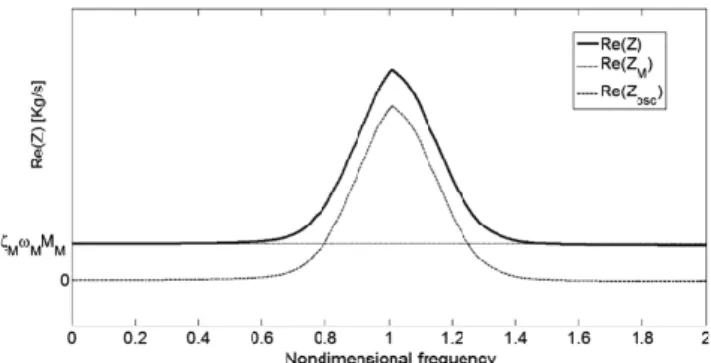
Z � jMM � ω−ω2M ω � � 2ζMωMMM � ωX N 1 � mn 1� 2jζoscω∕ωn 2ζoscω∕ωn� j��ω∕ωn�2− 1� � (7) As before, the real part of the impedance is shown in Fig. 3 together with the contributions of both subsystems. In this particular case, a constant damping ratio has been assumed for the master structure and for all the frequencies without precluding the usage of other damping models that can be a function of the frequency.
To assess the effect of this impedance on the main vibrating body, we can write the compliance transfer function of the assembled
system as the sum of the inverses of each dynamic stiffness, which will provide an idea of the displacements of the primary mass in function of the forcing frequency:
XM F � � MM�−ω2� 2jωωMζM� ω2M� �X N 1 mn � 2jωωnζosc� ω2n− � 2jωωnζosc� ω2n�2 −ω2� 2jωω nζosc� ω2n ��−1 (8) The previous equation can take a wide variety of forms depending on the definition of the secondary oscillators. To remain within the scope of this research, we will assume that there is a small amount of damping on each of the secondary oscillators �ζosc;min< ζosc< 2%�
and that the number of oscillators is very high to have a stable response on an averaged sense (N⋙1). For the numerical examples presented hereunder, without losing generality, we will assume the following nondimensional parameters: MM� 1, KM� 4π2,
ζM� 2%, mn� αMM∕N, ∀n, ζosc� 1%, whereas for the natural
frequencies of the secondary SDOF systems, a normal distribution will be assumed such that ωn∼ N �μ; σ�, in which μ and σ are,
respectively, the mean and standard deviation of the normal distribution N . Under these assumptions, the only parameters that can take a protagonistic role on the shape of the master response will be the overall percentage of added mass compared to the mass of the main system �α� and the probability density function (PDF) of the natural frequencies �N �μ; σ��.
A. Overall Mass Variation α
The total mass of the attached oscillators is written as a fraction of the mass of the main vibrating body. Since the earliest stages of the fuzzy-structure theory, it has been well known that the overall mass is one of the ruling parameters of the phenomenon of apparent damping. It is interesting to see how very few added mass can have a considerable impact on the response of the main resonator. As it is shown in Fig. 4, for increasing values of α, the main mode appears to be more damped, yet as a single mode, but for further values of α, the energy spreads over the neighboring pulsations where the natural frequencies of the oscillators have been defined. In this case, these two new peaks on the transfer function will originate a nonexponential decay in the case of free vibrations due to a broadband input as an impulse, for example, and a beat phenomenon will dominate the transient response. This idea will be easier to grasp
Fig. 3 Resistive part of impedance of the coupled system showing the contribution of the master and the fuzzy attachment.
Fig. 4 Amplitude of FRFs and transient response to impulse excitation for varying values of α; on the bottom left, the histogram showing the frequencies and amount of oscillators per frequency band.
29
30
in the following paragraph, in which variations of the ωn will be
considered.
A rough yet clear estimation can be done of the effective damping factor of the assembled system if a decreasing exponential is fitted through the maximum values of the peaks of the transient response for different values of α. The damping ratio produced by this fitting can be seen as a global parameter of the necessary time for vibration decay, regardless of the nature (exponential or not) of the response. Figure 5 shows this equivalent damping ratio for different values of the total mass of the oscillators while keeping all the other parameters constant. The dispersion is due to the finite number of added oscillators N. It is of particular interest to notice how there is a clear maximum damping value for a very small amount of added mass.
B. Variation of the Mean Value for the Oscillator Distribution μ
The second parameter that plays a paramount role on the response of the master motion is the location of the oscillators in the frequency axis. As was already presented in Fig. 3, the resistive part of the impedance increases only in the band that encompasses the natural frequencies of the oscillators; therefore, it is to be expected that, in the assembled system, the bigger the effect will be if these natural frequencies are close to the eigenfrequency of the mode of the master system, as shown in the following figure, in which different mean values μ are considered for the natural frequencies ωn.
Figure 6 shows three different cases, in which the mean value of the oscillator distribution varies. On the left-hand side is plotted the response in frequency together with the corresponding histogram that represents the oscillators, whereas on the right-hand side is found the transient normalized response of the coupled system.
C. Variation of the Standard Deviation for the Oscillator Distribution σ
The dispersion of the parasitic modes around the mean value is important as for big dispersions natural frequencies far away from the master mode will affect only the inertial characteristics of the assembled system. On the other hand, if all the secondary resonances are condensed in a very narrow band, the effect of apparent damping will be clearly marked on the transfer function of the system.
It can be easily shown that, for σ → 0, all the oscillators resonate at the same frequency, behaving as a single mass of value αMM, or in
other words, it becomes a classical mass damper. This limit can be as well deduced from the transfer function of Eq. (7) by considering ω1� ω2� · · · � ωn� ωM. In this case, the beat phenomenon
between the two new peaks of the transfer function becomes very clear, and the settling time of the assembly can be even higher than the one of the main resonator alone.
As done previously for the overall mass of the array, we can fit the transient response to the impulse by a decaying exponential and estimate roughly an equivalent damping factor. In Fig. 8 can be seen how, as in the case of the mass, there is a clear maximum of dissipation in function of the dispersion of the natural frequencies.
III. Numerical Implementation
The idea of coupling stochastically defined impedances to a main model of a complex machine is very attractive because, as shown previously, it allows explaining the elevated values of damping that are often seen in the low- to medium-frequency ranges while providing an interpretation that is practically independent of the actual dissipation rates and asymptotically stable.
Let us consider a generic complex assembly, intended as a master load-carrying structure plus a large number of NSCs assembled into it.
The objective is to have the capability of assessing vibration levels in the main structure, while including the effects of the NSC and not necessarily to determine directly the response upon these components. A numerical model should not be penalized by the
Fig. 5 Equivalent viscous damping of the master body in function of the mass of the oscillators.
Fig. 6 Amplitude of FRFs and transient response to impulse excitation for varying values of μ; on the bottom left, the histogram showing the frequencies and amount of oscillators per frequency band.
33
excessive amount of DOFs that would require a classical FE approach. The NSC is assumed to be excited only by its interfaces with the main structure, and therefore, the utilization of an effective mass model is justified.
As a starting point, it is assumed that a rather satisfactory FE representation of the main structure is available, which is often the case for aeronautical structures. In this model, the nodes corresponding to the source of excitation (S), receiver locations (R), and interfaces with the NSC (I) are identified, and the modal
basis is computed on these points up to a frequency that allows to synthesize transfer functions with feeble truncation errors with a standard FE solver. These sets of nodes, shown schematically in Fig. 9, are not required to be mutually exclusive. Following, the full transfer-function matrix is synthesized out of the P modes included in the analysis; in this case, such matrix represents an accelerance:
H�ω� �X P i�1 −ω2 ϕiϕ T i ω2 n;i− ω2� 2jζiωn;iω (9)
The computation of this matrix can require relatively high informatics resources, in computation time and storage size, because it will be of the size nelm�R ∪ S ∪ I�2× NFreqs, in which nelm�X�
indicates the number of elements in set X, and NFreqsthe frequency
steps used for the analysis. It must be noticed as well that this matrix has to be computed only once for all the future analysis and just recalculated if the main FE model has been altered.
For the sake of notation, with the matrix AStr
XY, we denote the
response on structure Str of the points in the X− Set caused by a unitary harmonic excitation on each of the points of the Y− Set. The global FRF matrix can be divided into the following symmetric submatrices that describe the transfers occurring between each of the included sets:
Fig. 7 Amplitude of FRFs and transient response to impulse excitation for varying values of σ; on the bottom left, the histogram showing the frequencies and amount of oscillators per frequency band
32 .
Fig. 8 Equivalent viscous damping of the master body in function of the dispersion of the oscillators in frequency (σ).
Fig. 9 Effective mass model schematics.
34
35
8 > > < > > : AMaster RS ∈ CR×S×NFreqs AMaster RI ∈ CR×I×NFreqs AMaster II ∈ CI×I×NFreqs AMaster IS ∈ CI×S×NFreqs (10)
These matrices being issued exclusively from the main FE model can be stored and loaded at each time for further analyses involving different distributions of the NSC parameters.
Once the properties of the cloud of oscillators have been defined [ωn∼ N �μ; σ�, α] and their locations identified on the set of
interfaces, it is possible to write for each interface the point accelerance exerted by the oscillators linked to the interface node k as the inverse of the apparent mass of the fuzzy structure:
Ak�ω� � 1 Mappk �ω� (11) in which Mappk �ω� �X N 1 mn 1� 2jζn�ω∕ωn� 1� 2jζn�ω∕ωn� − �ω∕ωn�2 ; ∀ n linked to node k (12) The coupled oscillators should not be intended as tiny resonating physical systems; it is more logical to interpret their overall impedance as an amount of resonating mass that is a continuous function of frequency, as in Eq. (12). (Recall that modal overlap is guaranteed by having a sufficient small amount of viscous damping in the oscillators ζosc> ζosc;min.)
Equation (11) will yield as many accelerance functions as the number of interfaces that were defined in the I set. These FRFs can be arranged in a diagonal matrix (ANSC
II ∈ CI×I×NFreqs) just like the
transfer matrices, depending exclusively on the master FE model [Eq. (10)]. Note that this matrix contains the functions representing the resonating mass that the master structure is seeing from the fuzzy, while being independent of the number N of modal contributions. It is because of this characteristic that a coupling in frequency domain has been preferred over other modal substructuring possibilities, such as component-mode-synthesis methods, in which the elevated number of added parasitic modes (N) would be penalizing. The size of the model is then given by the amount of interfaces and independent of the quantity of coupled oscillators (N).
Now that all the matrices have been defined, the transfer functions of the two substructures can be coupled to obtain the assembly response through the original equation of Jetmundsen et al. [24] for frequency-response-based substructuring, in which the response of the assembled system, intended as master structure plus oscillators, will be given by
ACoupledRS � AMaster
RS − �AMasterII � ANSCII �−1AMasterIS (13)
The latter formula is issued by imposing at both subsystems a spatial compatibility requirement on the interface DOFs and the reciprocity condition on the forces created at each interface as equal in modulus and of opposite signs. It must be noticed that this formulation requires only the inversion of one matrix of size (I × I) at each frequency step. This core matrix corresponds to the inverse of the transfer function between interfaces on the main structure plus the effects of the added parasitic dynamics. Being the matrix AMaster
II
invariant and with a known inverse, the core matrix ANSC II can be
interpreted as a first rank update of the original FE model matrix AMaster
II ; thus, for a very big number of interfaces, the inversion of the
core matrix can be improved from a numerical standpoint with the implementation of the Sherman–Morrison formula [25], in which the inverse of the sum of the two matrices is replaced by only vectorial multiplication.
Among the benefits of the proposed method, we highlight the possibility of replacing one or more of the matrices in Eq. (13) by experimentally determined transfer functions, in which case a hybrid
model with numerical and experimental parts can be obtained. For the sake of curiosity, the reader can refer to [26] for further information on the topic.
IV. Experimental Setup and Model Validation
The first empiric trial has been focused on only one representative category of NSCs to assess the viability of the model proposed. Because of their amount, overall weight in typical aeronautical structures, and spatial repartition, cable bundles are suitable candidates to assess their impact on the primary structure.
The recreation of the encountered phenomena in a small and controlled laboratory scale is not an easy task. The primary structure has to be well known, implying that its representation suits a deterministic treatment: its modal parameters are predictable through classic FE analysis and measurable with standard experimental-modal-analysis (EMA) techniques. As a consequence of the previously presented numerical results, we expect an active mass of the order of 1–5% of the mass of the main component, meaning that the specimen that will serve as primary structure must have important inertial properties to be able to respect this quantity while conforming to the size, weight, and security constraints of the laboratory. Last, but not least, the response of the primary structure must contain a sufficient number of modes in the frequencies of interest to originate the energy exchange under examination.
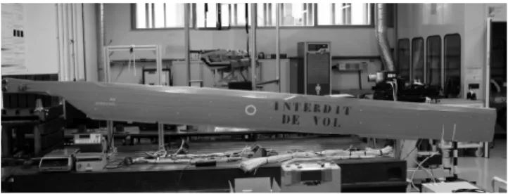
A helicopter blade has been chosen as primary structure because it can be considered as a relatively big and massive structure whose modal characteristics are measurable and predictable through EMA and FE analysis, respectively (Fig. 10). The blade has been clamped on one end and the measures have been performed through a Polytec® PSV-400 scanning laser vibrometer. The results have been posttreated in LMS Test. Lab® and the EMA accomplished with the LMS PolyMAX® stabilization algorithm in the [5−150] Hz band. Ten modes have been extracted with good modal quality indicators [mode indicator function (MIF), mean phase collinearity (MPC), and mean phase deviation (MPD)]. (MIF, MPC, and MPD are estimators of the quality of a mode extracted through EMA. They indicate, among other characteristics, how complex is the mode extracted.) For this first set of measurements, a random input was used to excite the structure. Measurements under harmonic excitation are currently ongoing to assess the effect of nonlinearities.
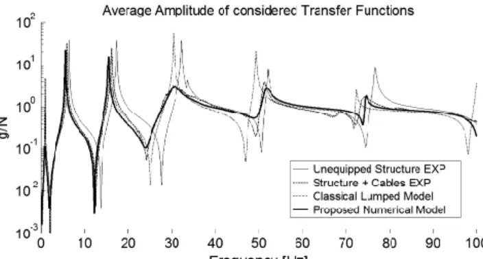
As a starting point, the results obtained with the baseline FE model of the blade have been compared to the measurements and the model has been validated in the band of interest. The comparison of the average amplitude of the transfer functions of all the points in the receiver set is shown in Fig. 12.
Once the FE model of the master structure has been validated, on one side of the blade, a considerable number of cable bundles have been installed at known locations to represent the NSCs that will
Fig. 10 Helicopter blade used as primary structure.
Fig. 11 Example of two experimental modes of the main structure.
37 38 39 40 41 6 LOUKOTA ET AL.
affect the dynamics of the main structure. The static mass of the set of bundles has been chosen to be around 10% the mass of the blade, which corresponds to nearly 3 kg of cables and supports. All the bundles have been manufactured strictly in the same manner (meaning that weight, dimensions, assembly, and installation have been common to all the cables; the variation between the behavior of each specimen will rise only from uncontrollable parameters) so to restrict the uncertainties for this first empiric experience.
Preliminary tests on a shaker table were performed on different bundles to assess their response in the spectrum considered. Some of the characteristics already reported by other authors have been confirmed in the preliminary tests. The variability between nominally identical bundles is considerable; the first mode that corresponds to the first bending seems to be the only present on the band of interest even if its location in frequency is heavily dependent on the tension applied to the cable.
In this laboratory experience, we can measure directly the point apparent mass of the bundles by installing the support of the cable upon a force transducer between the shaker table and the support. In this way, direct measures of the force developed at each interface can be performed as a function of frequency, and because the table is piloted in acceleration, we can simply estimate the apparent mass of the cable as M�ω� � F�ω�∕A�ω�. Recall that this is the transfer function that should be in the diagonal of the coupling matrix ANSC
II .
The force transducers between the cable and the shaker table can be seen in the overall setup in Fig. 13, whereas an example of experimentally determined apparent masses of different bundles is shown in Fig. 14.
Once these preliminary tests concluded, the cables were installed on one side of the helicopter blade and the measurements on the receiver set of points were repeated. The experimental results on the average magnitude of these monitoring points before and after the installation of the bundles are presented in Fig. 16.
It can be seen how, at the lowest frequencies, the cables act as a lumped mass with a value equivalent to their static mass as
limω→0Mapp�ω� � mstat, shifting the main structure dynamics to
slightly lower frequencies, as the assembled structure is heavier and the mass is well spread along the surface. This result exemplifies well why, for very low frequencies, the lumped-mass representation is convenient for the modeling of NSC. However, once the apparent mass of each bundle starts increasing because getting closer to its natural frequency, the leading consequence on the main structure is not only a frequency shift, but also, more importantly, an elevated damping effect, as shown in Fig. 16, an effect that, for obvious reasons, cannot be reproduced in a lumped-mass approach.
Finally, to validate the numerical proposal, the parameters for the definition of the statistical part of the model need to be identified. The reader must be reminded that these parameters are the PDF, which contains the natural frequencies and the overall amount of added mass (α). In this controlled laboratory experience, thanks to a series of repeated measurements to the single cable bundles, an experimental
Fig. 13 First preliminary tests to assess the first modes of the bundle candidates.
Fig. 14 Apparent masses and mean value of nominally identical cable bundles; in the figure are shown the single measured functions for different bundles (thin black lines) and their mean value (thick black line); the third curve (dotted line) shows the numerical counterpart used for the simulation of the assembled system
44 .
Fig. 15 Cable bundles installed on the back of the blade. Fig. 12 Comparison between test data (EXP) and numerical simulation
(FE model) on receiver set for the unequipped structure
42 .
Fig. 16 Impact of the cables upon the main structure highlighting the lumped-mass effect (darker gray shade) and the apparent damping phenomenon (lighter gray).
43
45
mean apparent mass was assumed to be the target for the coupling terms in matrix (ANSC
II ). By testing different PDFs (normal, uniform,
beta), it was found that the distribution that suits the most the reproduction of the test data is a beta distribution, such that ωn∼ Beta�2; 5�. An example of one of the numerical coupling terms
extracted from such distribution is shown in Fig. 14 together with the mean experimental function used as objective. To determine the quantity of resonating mass to be distributed within the oscillators (α) just by looking at the logarithmic-error function between the test data and the simulations with different values of α, a clear global minimum near α � 5% can be identified, as shown in Fig. 17. A simple optimization algorithm capable of dealing with local minimums could establish this value automatically.
Figure 18 shows the final results obtained with the previously determined parameters. Four averaged responses are presented: two experimental and two numerical. The experimental data are the same of Fig. 16, whereas the two numerical curves correspond to the results of the proposed model and to the industrial modeling standard, in which the NSCs, in this case the cables, are assumed to act only as lumped masses, and therefore, included exclusively in the mass matrix of the master FE model.
The model proposed introduces physical mechanisms that are capable of reproducing the measured response in the different frequencies. On the first part of the spectrum, the classical lumped-mass representation works well until the dynamics of the oscillators is activated. In this band (30−40 Hz), the response appears heavily damped, beyond reasonable values of damping factors if a viscous damping is to be applied to the damped mode. Once the influence of the oscillators has passed, the apparent mass of the secondary systems is lower than its static mass, thus provoking a shift toward slightly higher frequencies if compared to the lumped-mass idealization.
V. Conclusions
In this paper, a new numerical model conceived to reproduce the effects of NSCs upon the load-carrying structure has been introduced. Such a model is based on the theory of fuzzy structures and exploits
the effect of apparent damping as a modeling tool. This numerical representation offers the advantage of being compatible with the vast majority of standard industrial FE model; it can be interpreted as a nonintrusive coupling of two different models, or in other words, as a posttreatment of the original FE model.
As the transfer of energy between the two models, or apparent damping, is mostly ruled by the amount of vibrating mass per frequency band, the problem can be restated as finding the correct spectral mass distribution that can substitute the vibrating NSCs as seen by the master structure. This means finding the correct global mass value of the fuzzy (α) and the PDF, which spreads this mass along the frequency axis. Classical viscous damping is only required in the secondary oscillators to avoid the singularities in the natural frequencies; the actual value used is of little relevance. Through substructuring in the frequency domain, millions of small dynamic contributions can be taken into account in the numerical model at a very modest numerical cost.
An experimental test bench that provided a valuable mean of validation of the hypothesis underlying the model proposed has been presented as well. In these experiments, it has been shown how the NSCs used, in this case cable bundles, induced a behavior on the host structure that was reproducible with the numerical approach proposed.
This paper does not pretend to introduce the ultimate approach to simulate vibrational environments in complex assemblies, but only to demonstrate that the concept of apparent damping can be used as a powerful modeling tool. The idea introduced by Soize et al. 30 years ago still has a lot of potential in the low- to midfrequency barrier, and particularly for the comprehension and prediction of cabin dynamics in large commercial aircraft or other large and complex machines.
References
[1] Soize, C., “Probabilistic Structural Modeling in Linear Dynamic Analysis of Complex Mechanical Systems, I—Theoretical Elements,” La Recherche Aérospatiale, Vol. 5, 1986.
[2] Chabas, F., , Desanti, A., and Soize, C.et al., “Probabilistic Structural Modeling in Linear Dynamical Analysis of Complex Mechanical Systems, II—Numerical Analysis and Applications,” La Recherche Aérospatiale, Vol. 5, 1986.
[3] Soize, C., “A Nonparametric Model of Random Uncertainties for Reduced Matrix Models in Structural Dynamics,” Probabilistic Engineering Mechanics, Vol. 15, No. 3, 2000, pp. 277–294. [4] Friis, L., and Ohlrich, M., “Vibration Modeling of Structural Fuzzy with
Continuous Boundary,” Journal of the Acoustical Society of America, Vol. 123, No. 2, 2008, pp. 718–728.
[5] Soize, C., “Random Matrix Theory for Modeling Uncertainties in Computational Mechanics,” Computer Methods in Applied Mechanics and Engineering, Vol. 194, No. 12, 2005, pp. 1333–1366.
[6] Soize, C., and Batou, A., “Stochastic Reduced-Order Model in Low-Frequency Dynamics in Presence of Numerous Local Elastic Modes,” Journal of Applied Mechanics, Vol. 78, No. 6, 2011, Paper 061003. [7] Fernandez, C., “Modélisation et validation expérimentale des
complexes insonorisants pour la prévision vibroacoustique numérique basse et moyenne fréquences des automobiles,” Ph.D. Dissertation, Université Paris-Est, 2008.
[8] Batou, A., and Soize, C., “Uncertainty Quantification in Low-Frequency Dynamics of Complex Beam-Like Structures Having a High-Modal Density,” International Journal for Uncertainty Quantification, Vol. 3, No. 6, 2013.
[9] Koç, I. M., Carcaterra, A., Xu, Z., and Akay, A., “Energy Sinks: Vibration Absorption by an Optimal Set of Undamped Oscillators,” Journal of the Acoustical Society of America, Vol. 118, No. 5, 2005, pp. 3031–3042.
[10] Pierce, A. D., Sparrow, V. W., and Russell, D. A., “Fundamental Structural Acoustic Idealizations for Structures with Fuzzy Internals,” Journal of Vibration and Acoustics, Vol. 117, No. 3A, 1995, pp. 339– 348.
[11] Strasberg, M., and Feit, D., “Vibration Damping of Large Structures Induced by Attached Small Resonant Structures,” Journal of the Acoustical Society of America, Vol. 99, No. 1, 1996, pp. 335–344. [12] Weaver, R., “The Effect of an Undamped Finite Degree of Freedom
Fuzzy Substructure: Numerical Solutions and Theoretical Discussion,” Journal of the Acoustical Society of America, Vol. 100, No. 5, 1996, pp. 3159–3164.
Fig. 17 Logarithmic error of simulations for different active mass values (α) with respect to the experimental measurements.
Fig. 18 Average amplitude in the receiver set for numerical model compared to experimental measurements.
47 48 49 50 51 52 53 8 LOUKOTA ET AL.
[13] Nagem, R., Veljkovic, I., and Sandri, G., “Vibration Damping by a Continuous Distribution of Undamped Oscillators,” Journal of Sound and Vibration, Vol. 207, No. 3, 1997, pp. 429–434.
[14] Maidanik, G., “Induced Damping by a Nearly Continuous Distribution of Nearly Undamped Oscillators: Linear Analysis,” Journal of Sound and Vibration, Vol. 240, No. 4, 2001, pp. 717–731.
[15] Maidanik, G., and Becker, K., “Criteria for Designing Multiple-Sprung Masses for Wideband Noise Control,” Journal of the Acoustical Society of America, Vol. 106, No. 6, 1999, pp. 3119–3127.
[16] Akay, A., Xu, Z., Carcaterra, A., and Koç, I. M., “Experiments on Vibration Absorption Using Energy Sinks,” Journal of the Acoustical Society of America, Vol. 118, No. 5, 2005, pp. 3043–3049.
[17] Carcaterra, A., and Akay, A., “Theoretical Foundations of Apparent-Damping Phenomena and Nearly Irreversible Energy Exchange in Linear Conservative Systems,” Journal of the Acoustical Society of America, Vol. 121, No. 4, 2007, pp. 1971–1982.
[18] Carcaterra, A., “New Concepts in Damping Generation and Control: Theoretical Formulation and Industrial Applications,” Variational Models and Methods in Solid and Fluid Mechanics, edited by dell’lsola, F., and Gavrilyuk, S., Vol. 535, CISM Courses and Lectures, Springer, Vienna, 2012, pp. 249–313.
[19] Roveri, N., Carcaterra, A., and Akay, A., “Frequency Intermittency and Energy Pumping by Linear Attachments,” Journal of Sound and Vibration, Vol. 333, No. 18, 2014, pp. 4281–4294.
[20] Roveri, N., Carcaterra, A., and Akay, A., “Energy Equipartition and Frequency Distribution in Complex Attachments,” Journal of the Acoustical Society of America, Vol. 126, No. 1, 2009, pp. 122–128. [21] Vignola, J. F., Judge, J. A., and Kurdila, A. J., “Shaping of a System’s
Frequency Response Using an Array of Subordinate Oscillators,” Journal of the Acoustical Society of America, Vol. 126, No. 1, 2009, pp. 129–139.
[22] Vignola, J., Glean, A., Judge, J., and Ryan, T., “Optimal Apparent Damping as a Function of the Bandwidth of an Array of Vibration Absorbers,” Journal of the Acoustical Society of America, Vol. 134, No. 2, 2013, pp. 1067–1070.
[23] Maidanik, G., Becker, K., and Maga, L., “Replacement of a Summation by an Integration in Structural Acoustics,” Journal of Sound and Vibration, Vol. 291, No. 1, 2006, pp. 323–348.
[24] Jetmundsen, B., Bielawa, R. L., and Flannelly, W. G., “Generalized Frequency Domain Substructure Synthesis,” Journal of the American Helicopter Society, Vol. 33, No. 1, 1988, pp. 55–64.
[25] Sherman, J., and Morrison, W. J., “Adjustment of an Inverse Matrix Corresponding to a Change in One Element of a Given Matrix,” Annals of Mathematical Statistics, 1950, pp. 124–127.
[26] Nicgorski, D., and Avitabile, P., “Conditioning of FRF Measurements for Use with Frequency Based Substructuring,” Mechanical Systems and Signal Processing, Vol. 24, No. 2, 2010, pp. 340–351.
54