ICAST2014 036
Electrical tuned vibration absorber: application of the equal-peak
method to linear and non-linear RL piezoelectric shunts
Gilles TONDREAU
1*, Arnaud DERAEMAEKER
1,Payam SOLTANI
2,Gaëtan KERSCHEN
2 1Building Architecture and Town Planning (BATir), Université libre de Bruxelles, Belgium.
2
Dept. of Aerospace and Mechanical Engineering, University of Liège, Belgium.
Abstract
Mechanical tuned vibration absorbers (MTVAs) are devices used to mitigate the vibrations of a structure around one of its eigenfrequencies. By introducing an additional degree of freedom in the structure, MTVAs allow to split the peak of interest in the frequency response in two peaks with lower amplitudes. The design of MTVAs is usually based on the (approximate) equal-peak method proposed by Den Hartog. A closed-form exact solution was however obtained by Asami and Nishihara, for which the two peaks of the frequency response have exactly the same amplitude. Similarly to MTVAs, piezoelectric tuned vibration absorbers (PTVAs) allow to damp efficiently a specific peak of the frequency response. Although a pole placement technique can be used to design such devices, tuning rules are usually based on approximate equal-peak methods which define the optimum values of the resistor and the inductance of the shunt. Very recently, Asami and Nishihara’s exact solution has been extended for the equal-peak method to PTVAs by the authors of the present paper. The first contribution of this paper is to illustrate this new optimum design of a series RL piezoelectric shunt on a realistic example. A clamped-free steel plate excited with two piezoelectric actuators and shunted with two piezoelectric transducers is modelled using plate elements (laminates). Non-linearity is then introduced in the host structure, and a new non-linear PTVA for mitigating the vibrations of the non-non-linear host structure is proposed. The improvement of damping performances in the presence of structural non-linearties using a non-linear PTVA is illustrated.
1. INTRODUCTION
The mechanical tuned vibration absorber (MTVA) is the most popular anti-vibration device [16] which has been applied mainly on civil engineering structures such as the Taipei World Financial Center in Taiwan and the Millenium Bridge in London. For smaller structures, the additional mass required by the MTVA might be too invasive, so that other solutions are desirable. The piezoelectric tuned vibration absorber (PTVA) is a widely used alternative in which a piezoelectric transducer is connected to an electrical circuit. Typically, the vibrational energy is converted in electrical energy in the piezoelectric transducer and then dissipated in a resistor. The efficiency of PTVAs is strongly increased by considering resonant shunts, in which inductors and possibly capacitors are added to the electrical circuit [8]. Despite
*
some authors have proposed to tune the piezoelectric shunt based on a pole placement strategy such as in [6,2], the most successful approach is based on an equal peaks strategy, similarly to Den Hartog’s tuning rule for MTVAs [10]. Initially adapted to shunted structures by Hagood and von Flotow [5], the basic idea consists in choosing adequately the values of the resistor and the inductor, so that the main peak to be damped is splitted in two peaks with identical smaller amplitude. Extensions of Hagood’s tuning rule to damp several mode shapes have been proposed in the literature [3], and some authors have also investigated non-linear shunting strategies [1,18].
The aforementioned strategies for equal peaks design of vibration absorbers are only approximate and do not give peaks with exactly the same amplitude. However, an exact solution to the MTVA has been recently developed in [9], and extended to piezoelectric shunts by Soltani et al. in [14], based on the dimensionless form of the one degree-of-freedom modal model of an undamped host structure. The objective of the present paper is to apply the new exact solution to the equal peaks design of piezoelectric shunts on a realistic numerical case study in the presence of non-linearities. The paper is organized as follows: Section 2 presents the classical tuning rules of RL series piezoelectric shunts as well as the new exact solution. Section 3 deals with the numerical case study which consists in a clamped-free plate equipped with two piezoelectric actuators and two piezoelectric shunts and to which a cubic spring is attached to simulate the non-linearities. A very simple technique for identifying the equivalent dimensionless parameters from the capacitance measurement is presented and the performances of linear and non-linear shunts for the mitigation of vibrations of the first bending mode shape of the plate is studied. In particular, non-linearity is added to the linear shunt designed with the new exact solution to improve the performances of the shunt in the presence of non-linearities. Finally, Section 4 concludes the paper with perspectives for future research studies.
2. ELECTRICAL TUNED VIBRATION ABSORBER
2.1. Governing equations of a structure coupled to a piezoelectric shunt
Fig. 1 shows the one degree-of-freedom modal model of an undamped host structure to which a piezoelectric (PZT) transducer in series with a RL shunt is connected:
Figure 1:Piezoelectric vibration absorber with a (series) RL shunt. The governing equations of the structure coupled to the series RL shunt read [5]:
̈ ( )
where
( ), and √
. (2)
is the capacitance between the electrodes of the PZT with no external force, the capacitance
under constant strain and the electromechanical coupling factor. It is more convenient to consider the following parameters similarly to the work of Agnes and Inman [1]:
√ ,
√ , , , ̃ √ , ̃ √ , , , √ and √
(3)
Introducing the parameters of Eq. (3) into Eq.(1) leads to the dimensionless governing equations: ̃ ̃ ̃
̃ ̃ ̃ ̃ , (4)
where the prime stands for the derivative with respect to . It is important to point out that while depends only on the transducer and is usually provided in datasheets, depends on the structure and can only be identified when the PZT transducer is mounted on the structure. Is it related to the generalized electromechanical coupling coefficient [5,14]. Solving Eq.(4) gives the receptance transfer function of the primary mass:
( ) | ̃| |
( ) ( ) | (5)
2.2. Tuning rules
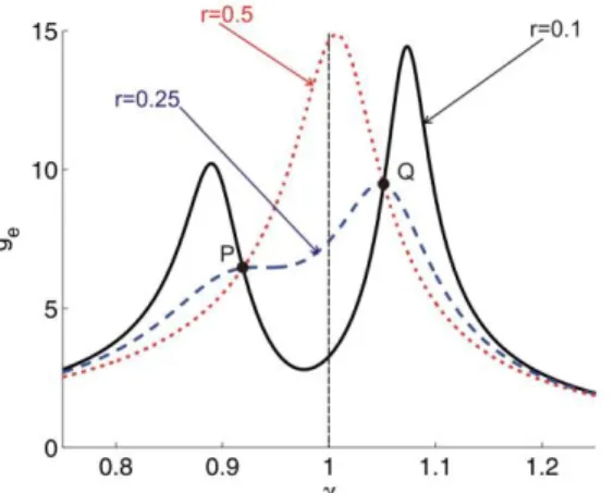
As explained in the previous section, the value of is fixed for a given structure. The tuning of a RL shunt consists therefore in choosing the appropriate values of the frequency tuning and damping parameters and . The classical tuning rule which has been proposed by Hagood and von Flotow in [5] has been inspired by Den Hartog’s fixed point method which is widely applied for the design of MTVAs [10]. The main idea is based on the existence of fixed points for which all the frequency responses of the undamped primary system coupled to a secondary mass cross, whatever the value of the damper. The same principle can be extended to PTVAs: the frequency responses of the shunted structure cross at fixed points 𝑃 and 𝑄 whatever the value of in the case of an undamped host structure, as illustrated in Fig. 2.
Figure 2:Illustration of fixed points 𝑃 and 𝑄 ( and ).
Hagood and von Flotow consider that the optimum design of the series RL shunt is obtained when two conditions are satisfied. The first condition is that the two fixed points must have the same amplitude. This can be exactly satisfied by taking 𝑜𝑝𝑡 . The second condition is that the amplitude of the
receptance at 𝑜𝑝𝑡 should be the same than the amplitude of the fixed points: ( ,𝑄)
( 𝑜𝑝𝑡). This second condition can approximatively be satisfied for 𝑜𝑝𝑡 √2 . More recently, Yamada et al. have proposed an improvement of the tuning rule in [17]. They also suggest that the optimum damping is obtained for 𝑜𝑝𝑡 , but on the contrary to Hagood and von Flotow, they consider that the optimum damping ratio is obtained when the derivative of the receptance is zero at the fixed points, meaning that they correspond to maxima:
𝑑 ( )
𝑑 |𝛾 ,𝛾 (6)
Again, this second condition cannot be exactly satisfied, but almost achieved by taking 𝑜𝑝𝑡 √ 𝛼√ 𝛼 .
2.3. New exact tuning rule
A new exact solution for the 𝐻∞ optimization of piezoelectric materials shunted with series RL shunt has recently been proposed in [14]. Since a fixed-point-based absorber design cannot lead to peaks of equal amplitude, the same approach than the technique adopted by Nishihara and Asami in [9] for the exact solution of the equal peaks design for MTVAs has been adopted. The solution is obtained by only focusing on the resonant points 𝐴 and 𝐵 without considering the existence of fixed points 𝑃 and 𝑄. Because the resonant points need to have equal amplitude, we have ‖ ( )‖∞ ( 𝐴) ( 𝐵). The objective here is to find and so that ℎ ‖ ( )‖∞ is minimized. A long analytical calculation not detailed here leads to the following optimum values of and (the interested reader is referred to [14]):
𝑜𝑝𝑡 2√ 𝑎̃ 𝑏̃𝑎̃ , 𝑜𝑝𝑡 √
[ (𝛿 )(𝛼 𝜒 )ℎ ]
[ (𝜒𝛿 )ℎ ]𝛿 , (7)
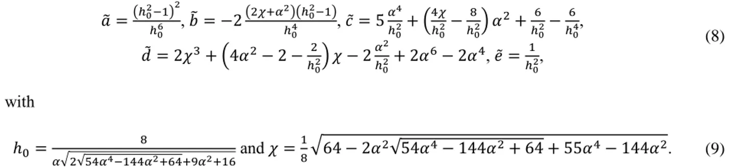
𝑎̃ (ℎ ) ℎ , 𝑏̃ 2 ( 𝜒 𝛼 )(ℎ ) ℎ , 𝑐̃ 𝛼 ℎ ( 𝜒 ℎ 8 ℎ ) 6 ℎ 6 ℎ , 𝑑̃ 2𝜒 ( 2 ℎ ) 𝜒 2𝛼ℎ 2 6 2 , 𝑒̃ ℎ , (8) with ℎ 8 𝛼√ √5 𝛼 𝛼 6 9𝛼 6 and 𝜒 8√6 2 √ 6 . (9)
Fig. 3 compares the three tuning rules that have been presented for . This value has been considered because it corresponds to the value of for the numerical case study that will be investigated in Section 3.
(a) (b)
(b)
Figure 3:Comparison of the performances of the tuning rules. (a) Overall view; (b) Close-up at the first peak; (c) Close-up at the second peak.
The overall view shows that the Yamada and the exact rules are very similar and give much better performances than Hagood. However a closer look at the resonances of receptance reveals that while Yamada’s rule leads to peaks with slightly different amplitudes, the exact rule provides peaks with exactly the same amplitude. Actually, it has been illustrated in [14] that the exact rule always gives peaks of equal
amplitude, while the difference between the amplitude of the peaks increases as (coupling between the PZT and the structure) increases for Yamada’s rule.
3. NUMERICAL APPLICATION TO A REALISTIC EXAMPLE
3.1. Description of the case study
In order to illustrate the new equal peak method described in Section 3.3., we investigate the structure shown in Fig. 4:
(a) (b)
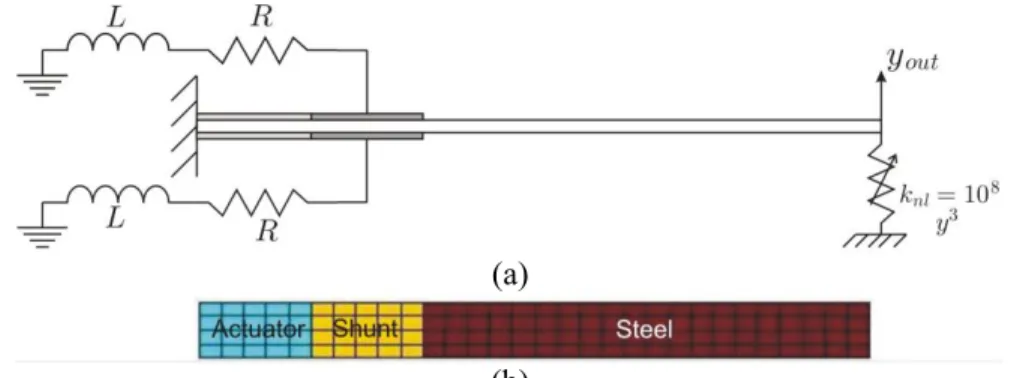
Figure 4:Clamped-free plate with two piezoelectric actuators and two identical piezoelectric shunts (a) Side view; (b) Bottom view (finite elements model).
The structure consists in a 3 × 2 × 2 clamped-free steel plate which is actuated with two × 2 × 2 identical piezoelectric patches. Two other piezoelectric patches identical to the actuators are connected to a resonant series RL shunt in order to damp the vibrations of the first bending mode shape of the plate. The vertical displacement at the free end of the beam is attached to a non-linear spring in order to investigate the performances of the shunt in the presence of non-linearities, as it will be discussed more into details in Section 3.4. Table 1 gives the material properties of the plate which has been modeled with 120 plate elements (laminates) using the Structural Dynamics Toolbox under Matlab [13].
Table 1: Material properties (ε0=8.854pF/m).
E (GPa) ν (/) ρ (kg/m3) d
31(=d32) (pC/N) ε11/ ε0 (=ε22/ ε0) (/)
Steel plate 71 0.3 2700 / /
PZT 66 0.3 7800 -190 1600
The frequency response of the vertical displacement at the free end of the plate when it is excited with the two piezoelectric actuators is studied. The results with and without shunt are obtained using a Craig-Bampton reduction, in which 5 degrees of freedom are taken into account (four electrical DOFs and the vertical displacement at the free end of the plate) as well as the first 20 mode shapes. A modal damping of ξ=0.1% is also introduced.
3.2. Identification of the equivalent dimensionless parameters
As discussed in Section 2, all the tuning rules rely on the dimensionless form of the governing equations of a one-degree-of-freedom modal model of the host structure with shunted piezoelectric materials. Basically, this calls for the identification of the dimensionless parameter of Eq. (5) from the multi-degree of freedom system response as well as the identification of for the mode i of interest. In this paper, we propose a very simple and fast technique which gives quite good estimates of these two parameters. This method relies exclusively on the measurement of the capacitance (using an impedancemeter for instance) of the piezoelectric patches installed on the structure, as illustrated in Fig. 5.
(a) (b)
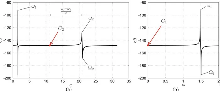
Figure 5:Use of capacitance measurement for the identification of equivalent dimensionless parameters. (a) Capacitance including the two first mode bending mode shapes; (b) Zoom of capacitance around the
first bending mode shape.
A typical capacitance curve of piezoelectric materials presents resonances followed by anti-resonances. Since the capacitance is defined as 𝑄 , this means that the resonances correspond to short circuit eigenfrequencies, while the anti-resonances correspond to the open circuit eigenfrequencies. It is therefore very easy to deduce the generalized coupling factor by identifying the resonance and the anti-resonance of the mode shape of interest. Indeed, the generalized coupling factor can be approximated as:
√ (10)
Using one of the three design rules of Section 2, it is then very easy to deduce and based on the estimate of . The next step is to deduce the values of and using Eq. (3), and has therefore to be identified first. Generally speaking, the open circuit and short circuit eigenfrequencies of mode i are related by the following relationship, where is the asymptotic capacitance on the left of the peak corresponding to the eigenfrequency of interest [2]:
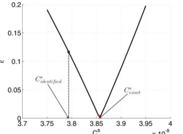
can therefore be very easily be deduced. If the mode shape corresponding to the first peak in the capacitance curve is the mode of interest, is simply the static capacitance as shown in Fig. 5(b). On the other hand, if the mode to be damped is not the first one, it is much more difficult to assess the asymptotic value . In this study, we propose to consider the value of the capacitance at the mean frequency between the short circuit eigenfrequency of the mode shape of interest, and the previous one. It is important to note that this approach is purely empirical and is valid for PZT patches, as well as PZT rods. Of course, the value of which is computed with this approach is approximate, but close to the correct value. In Fig. 6, we plot the relative difference | (𝛾 ) (𝛾 )(𝛾 )| of amplitudes of points 𝑃 and 𝑄 when applying Hagood’s rule for different values of . Since Hagood’s rule aims at having fixed points 𝑃 and 𝑄 of equal amplitude, the difference between their amplitudes allows to identify the exact value of : it corresponds to points 𝑃 and 𝑄 with identical amplitude.
Figure 6:Difference of relative amplitude of fixed points 𝑃 and 𝑄 for different estimates of . The error on the estimate of is very small: the identified value is only 1.56% smaller than the exact value. However, the difference of amplitudes of the receptance at fixed points 𝑃 and 𝑄 is very sensitive to the value of : despite the very nice estimate of with the proposed method, the difference of the amplitudes of points 𝑃 and 𝑄 is around 11% and can therefore not be neglected.
3.3. Results: linear shunt installed on a non-linear host structure
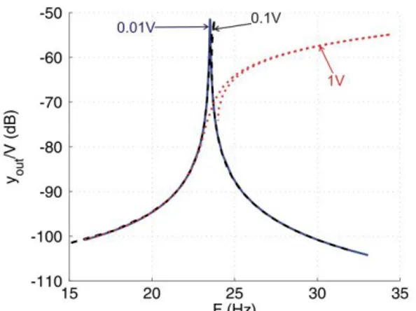
Let us now focus on the non-linear behavior of the clamped-free plate attached to a cubic spring as illustrated in Fig. 4(a). Such a non-linearity is realistic, since it has been achieved experimentally in [7], where the authors considered a main clamped steel beam connected to a secondary very thin beam clamped on the other side of the setup. In this case, increasing the force excites the non-linearity, as shown in Fig. 7 for the structure alone (not connected to the shunt). An in-house path-following algorithm combining shooting and pseudo-arclentgth continuation similar to [12] is used for computing the non-linear normal modes (NNMs) of the model and allows to compute the non-non-linear frequency response.
Figure 7:Non-linear frequency response for an increasing voltage applied to the PZT actuators. The bending of the main peak leads to unstabilities. Indeed, Fig. 7 suggests that at 30Hz for instance, the amplitude of the tip of the plate can be less than -100dB or much bigger (more than -60dB). It is not possible to predict what will be the response of the system, since it is very sensitive to the initial conditions. Such a situation is therefore unacceptable in many cases. Using the procedure based on the capacitance measurement which has been described in Section 3.2., and applying the exact tuning rule of Section 2.3., we have identified the optimum values of the RL shunts shown in Fig. 4. Table 2 summarizes the identified dimensionless parameters, as well as the values of the inductor and the resistor of the series RL shunt.
Table 2:Electrical and dimensionless properties. (nF) (/) (/) (/) (H) (Ω) 37.94 0.1854 1.0001 0.2305 1661 20206
Connecting the series RL shunt allows to efficiently reduce the vibrations of the first bending mode shape when it is excited with a voltage of 1 V applied on the PZT actuators as it can be seen in Fig. 8. The damping performances are still very efficient for an actuation of 5V, despite the small detuning (small increase of second peak). Finally, the shunt is completely detuned for an excitation of 7.5V.
Note that despite the fact that we use the exact rule, the peaks do not have exactly the same amplitude. It comes from the fact that (i) the host structure is slightly damped, and that (ii) the identification of is not exact. This will be discussed more into details in Section 3.5.
3.4. Results: non-linear shunt installed on a non-linear structure
Habib et al. have proposed an extension of the Den Hartog’s rule in order to deal with non-linearities in the context of mechanical tuned vibration absorbers in [4]. The non-linear rule that they propose is to choose the mathematical form of the non-linear MTVA which is a ‘mirror’ of the host structure. This means that if the non-linearity appears as a non-linear spring of order n, the MTVA should also include a non-linear spring of order n. In addition, the MTVA should contain a linear component in order to be able to mitigate correctly the vibrations in a linear regime, when the non-linearities are not activated for low amplitudes of forces. In this paper, we apply the mirror rule in order to correct the tuning of the piezoelectric shunt in the case of non-linearities. An early example of the application of non-linear piezoelectric shunt can be found in [15]. While the authors of [4] have also proposed a non-linear generalization of the equal peaks method, this still has to be extended to piezoelectric shunts. For that reason, the non-linear coefficients of the non-linear piezoelectric shunts have been obtained by trial and error. In the numerical case study investigated in the present paper, the non-linearity is modelled as a cubic spring. Therefore, the extension of Eq. (1) to a non-linear one degree-of-freedom modal model of an undamped host structure connected to a cubic non-linear shunt reads:
̈ ( ) ̈ ̇
(12)
Since the linear part and cubic part of the piezoelectric shunt can be designed separately, the previous values of R and L remain unchanged. By trial and error, the value 9 has been found to give
very nice performances. The results obtained with the non-linear piezoelectric shunt are illustrated in Fig. 9:
Figure 9: Frequency response of the non-linear host structure connected to a non-linear piezoelectric
A clear improvement of the shunt performances can be observed: while a huge instability was observed for 7.5V, the unstability is much smaller with a non-linear piezoelectric designed with the mirror rule, since the bending of the first peak is smaller (smaller hardening effect).
3.5. Practical issues for the design of shunts on real structures
Despite the very nice performance of the non-linear piezoelectric shunt which have been illustrated in the previous section, there are several issues to be pointed out which are particularly important for successful applications on real cases. First of all, the empirical technique discussed in Section 3.2. for identifying the equivalent properties of the one degree-of-freedom modal model can be improved. A technique based on curve fitting of a one-degree-of-freedom modal model and the real structure is likely to provide better estimate of the dimensionless parameters. Another issue is that damping is always present on real structures. This calls for a modification of the exact tuning rule by taking into account a damping on the primary structure. Also, the optimum damping requires very particular values of and . However, manufacturers of electrical devices are only able to provide devices of specific properties, so that the ideal tuning parameters are usually impossible to obtain. A very interesting sensitivity analysis of the performances of series and parallel RL shunts with respect to mechanical and piezoelectric properties as well as resistor and inductor values can be found in [11] in the case of linear shunts. Such a study should also be led with non-linear shunts. Using two independent piezoelectric shunts is also debatable. In practice, piezoelectric shunts will never be identical because of materials variability. This leads to resonant RL shunts with very close but different resonances, which can be problematic. A better approach would be to connect the piezoelectric patches in series and couple them to a single series RL shunt. Finally technological issues have to be taken into account: while resistors of a few dozen kΩ can very easily be found on the market, inductors of several kH as it has been identified in Section 3.3. cannot be found as such in the market, and have to be synthetized electronically (typical commercial inductors range from 0.1µH to 1H at the best). The practical implementation of the non-linear coefficient of the charges in
Eq. (12) has also to be studied.
4. CONCLUSION
In this paper, we have presented an exact solution for the equal peaks design of resonant RL series piezoelectric shunts. Since this technique is based on a dimensionless form of a one-degree-of-freedom modal model, we have also proposed a very simple technique using the capacitance measurement of the piezoelectric transducer installed on the structure and that will be connected to the shunt to identify the equivalent dimensionless parameters of the mode shape to be damped. The identified parameters have been found to be very close to the exact ones, for which the application of the well-known Hagood’s tuning rule leads to fixed points of the receptance of equal amplitudes. The exact rule has been applied on a realistic numerical case study which consists in a clamped-free plate actuated with two piezoelectric actuators, and shunted to two identical RL series piezoelectric shunts. A cubic non-linearity has also been considered and the results show that adding a cubic non-linearity in terms of charge to the RL shunt designed with the new exact rule enhances the stability of the piezoelectric shunt. Several practical issues have been pointed out for a successful application of non-linear piezoelectric RL shunts on real cases. In particular, the identification of equivalent dimensionless parameters will be improved, and a sensitivity analysis of the performances of the shunts with respect to material properties (mechanical, electrical and piezoelectric) will be investigated. The present paper is a preliminary theoretical and numerical study for
the development of an experimental demonstrator in order to illustrate the use of non-linear piezoelectric series RL shunt to mitigate vibrations in the presence of structural non-linearities.
ACKNOWLEDGMENTS
All authors, G. Tondreau, A. Deraemaeker, P. Soltani and G. Kerschen, would like to acknowledge the financial support of the Belgian National Science Foundation FRS-FNRS (PDR T.0028.13). The author G. Kerschen would like to acknowledge the financial support of the European Union (ERC Starting Grant NoVib 307265).
REFERENCES
1. Agnes, G.S. and Inman, D.J., “Nonlinear piezoelectric vibration absorbers”, Smart Materials and
Structures, Vol. 5, No. 5, 1996, pp. 704-714.
2. de Marneffe, B., “Active and passive vibration isolation and damping via shunted transducers”, PhD thesis, Université libre de Bruxelles, 2007.
3. Fleming, A.J., Behrens, S. and Moheimani, R., “Optimization and implementation of multimode piezoelectric shunt damping systems”, IEEE/ASME Transactions on Mechatronics, Vol. 7, No.1, 2002, pp. 87-94.
4. Habib, G., Detroux, T., Viguié, R. and Kerschen, G., “Nonlinear generalization of Den Hartog’s equal-peak method”, submitted to Mechanical Systems and Signal Processing, 2014 (published). 5. Hagood, N.W. and von Flotow, A., “Damping of structural vibrations with piezoelectric materials
and passive electrical networks”, Journal of Sound and Vibration, Vol. 146, No. 2, 1991, pp. 243-268.
6. Høgsberg, J. and Krenk, S., “Balanced calibration of resonant shunt circuits for piezoelectric vibration control”, Journal of Intelligent Material and Structures, Vol. 23, No. 17, 2012, pp. 1937-1948.
7. Kerschen, G., Lenaerts, V. and Golinval G.C., “Identification of a continuous structure with a geometrical non-linearity. Part I: Conditioned reverse path method”, Journal of Sound Vibration, Vol. 262, 2003, pp. 889-906.
8. Mohameini, S., “A survey of recent innovations in vibration damping and control using shunted piezoelectric transducers”, IEEE Transactions on Control Systems Technology, Vol. 11, No. 4, 2003, pp. 482-494.
9. Nishihara, O. and Asami, T., “Closed–form solutions to the exact optimizations of dynamic vibration absorbers (minimizations of the maximum amplitude magnification factors)”, Journal of
Vibration and Acoustics, Vol. 124, No. 4, 2002, pp. 576-582.
10. Ormondroyd, J. and Den Hartog, J., “The theory of the dynamic vibrations absorber”, Transaction
of the ASME, Vol. 50, 1928, pp. 9-22.
11. Park, J.W. and Han, J.H., “Sensitivity analysis of damping performances for passive shunted piezoelectrics”, Aerospace Science and Technology, Vol. 33, No. 1, 2014, pp. 16-25.
12. Peeters, M., Viguié, R., Sérandour, G., Kerschen G., and Golinval, J.C., “Nonlinear normal modes, Part II: towards a practical computation using numerical continuation”, Mechanical
Systems and Signal Processing, Vol.23, No. 1, 2009, pp. 195-216.
14. Soltani, P., Kerschen, G., Tondreau, G. and Deraemaeker, A., “Piezoelectric vibration damping using resonant shunt circuits: an exact solution”, submitted to Smart Materials and Structures, 2014 (accepted for publication).
15. Soltani, P., Tondreau, G., Deraemaeker, A. and Kerschen, G., “Linear and nonlinear piezoelectric shunting strategies for vibration mitigation”, In CNSDD2014, Agadir, Morocco, May 2014. 16. Sun, J. Jolly, M.R. and Norris, M., “Passive, adaptive and active tuned vibration absorbers – a
survey”, Journal of Mechanical Design, Vol. 117, No. B, 1995, pp. 234-242.
17. Yamada, K., Matsuhisa, H., Utsuno, H. and Sawada, K., “Optimum tuning of series and parallel LR circuits for passive vibration suppression using piezoelectric elements”, Journal of Sound and
Vibration, Vol. 329, No. 24, 2010, pp. 5036-5057.
18. Zhou, B., Thouverez, F. and Lenoir, D., “Essentially nonlinear piezoelectric shunt circuits applied to mistuned bladed disks”, Journal of Sound and Vibration, Vol. 333, No. 9, 2014, pp. 2520-2542.