HAL Id: hal-01440192
https://hal-amu.archives-ouvertes.fr/hal-01440192
Submitted on 23 Jan 2017
HAL is a multi-disciplinary open access
archive for the deposit and dissemination of
sci-entific research documents, whether they are
pub-lished or not. The documents may come from
teaching and research institutions in France or
abroad, or from public or private research centers.
L’archive ouverte pluridisciplinaire HAL, est
destinée au dépôt et à la diffusion de documents
scientifiques de niveau recherche, publiés ou non,
émanant des établissements d’enseignement et de
recherche français ou étrangers, des laboratoires
publics ou privés.
A new methodology to optimize spiral bevel gear
topography
Emmanuel Mermoz, Julien Astoul, Marc Sartor, Jean-Marc Linares, Alain
Bernard
To cite this version:
Emmanuel Mermoz, Julien Astoul, Marc Sartor, Jean-Marc Linares, Alain Bernard. A new
method-ology to optimize spiral bevel gear topography. CIRP Annals - Manufacturing Technmethod-ology, Elsevier,
2013, 62, pp.119 - 122. �10.1016/j.cirp.2013.03.067�. �hal-01440192�
A new methodology to optimize spiral bevel gear topography
Emmanuel Mermoz (3)
a,*
, Julien Astoul
a, Marc Sartor
b, Jean Marc Linares (2)
c, Alain Bernard (1)
d´
´ ´
´
¨
a
EUROCOPTER, Aeroport de Marseille Provence, 13700 Marignane, France
b
Universite de Toulouse, INSA, UPS, Mines Albi, ISAE, ICA (Institut Clement Ader), 135, avenue de Rangueil, F-31077 Toulouse, France
c
Aix-Marseille Universite, CNRS, ISM UMR 7287, 13288 Marseille Cedex 09, France
d
Ecole Centrale de Nantes, IRCCyN, UMR CNRS 6597, BP 92101, 1 rue de la Noe, 44321 Nantes Cedex 3, France
1. Introduction regarding MGB specificities
Main Helicopter Gearboxes (MGB) are high-tech devices that must transmit very high mechanical power, with a significant reduction in speed, at lower weight while occupying the least space possible. So, it is necessary to undertake a heavy and long development process before reaching a gearbox design that satisfies all the economic, technical and security requirements and especially that allows thousands of flight hours [1]. Customers attach particular importance to weight criterion, this one being a key factor in terms of profitability. So, housings are generally made of light alloys like Aluminium or Magnesium. A large part of the rotor loads being transferred to the airframe by the MGB, especially very high torques, housing undergoes high deflections that make the design of MGB a specific case regarding gear optimization. Under flight loads, gears can suffer from a displacement in the order of magnitude of 1 mm. The gear specialist has to ensure a proper behaviour in a set of positions that are the results of MGB external loads conditions in conjunction with the MGB internal stiffness. An optimized mechanical behaviour is ensured mostly by a correct geometrical position of contact areas and an acceptable Hertz pressure. For that purpose, the designer has to optimize geometrically the initial tooth flank of the gears by a set of corrections between 10 and 200
m
m. Finding the right optimiza-tion is sometimes very long and several loops of topography adjustments of a few microns may be required. The order of magnitude of the local deflection induced by Hertz pressure phenomena is no more than a few microns, so the optimization window is quite small. This sensitivity of the topography has also an impact on the manufacturing tolerances of power gears that arevery narrow. The aim of this paper is to present a new methodology to optimize the topography of spiral bevel gears.
2. A review of previous works on spiral bevel gear simulation and optimization
2.1. Loaded meshing simulation
¨
In 1987, Madrosky [2] proposes a loaded meshing model rather advanced for his time. Indeed, it already takes into account the flexibility of teeth. Those are calculated by the finite element method. The other part of the system is considered infinitely rigid. The relative displacements of the axes of the gears result from the deformation of the complete device. The contact stiffness is deduced from the Hertz theory. The latter gives contact dimen-sions and pressure. Gosselin [3] simulates the meshing of various tooth flank topographies, using the same techniques as Madrosky. He recommends maximizing contact ratio to improve load sharing. Lelkes [4] simulates the behaviour of gears manufactured according to the Palloıd method, also referring to the same technique. However, the Hertz theory is based on assumptions inconsistent with some contact properties of spiral bevel gears. Indeed, the opposite surfaces are conforming, the bodies are finished and they slide in the contact zone. De Vaujany [5] opts for an approach that combines finite elements analyses to evaluate tooth bending effects and the Boussinesq and Cerruti theory to model the contact deformations. Alves [6] accelerates the computation of the stiffness of teeth, wheels and sails by introducing a set of interpolation functions. Bibel [7] deals with the loaded meshing using directly PATRAN finite element models. The contact is treated by the computational code MARC. Litvin [8]
and Argyris [9] adopt the same approach. However, they use the software Abaqus. The meshes are automatically built from the
Keywords: Optimization, Finite element, method, Spiral bevel gear
This paper aims to present the new method developed to generate optimized spiral bevel gear surfaces. Thanks to a complex non linear finite element model, the geometrical gear meshing positions under operational loads are first precisely computed. These meshing positions are then used as inputs of a calculation process that seeks to define the best tooth surface topography. So far, this activity was based on sensitivity studies conducted directly by the designer, which led to repeat calculations whose progress was difficult to control.
EUROCOPTER uses now optimization algorithms to compute automatically the surfaces of the tooth contact flanks. This approach leads to higher performances of the gear while reducing the development time. This paper describes the new process implemented to design the tooth shape, and illustrates its interest through an example.
points generated on the tooth flanks without using a CAD software. The finite element modelling of the teeth is more accurate and faster. The work presented in this paper is based on a similar technique. The model proposed by Litvin [10] features three teeth
(Fig. 1). The flexibility of the tooth is taken into account, the gear
itself being considered fixed. A torque is applied along the pinion axis. The simulation results highlight every potential contact on tooth edges. Vimercati [11] also uses a computational code based on the finite element method. His work shows that the contact ratio increases with the torque while the quasi-static transmission error decreases.
2.2. Gear topography optimization
Papers dealing with the optimization of the loaded spiral bevel gear behaviour are relatively recent. Simon [12] analyses the and the magnitude of the quasi-static transmission error. The considered tool profile is made of two tangent arcs. Their radius and the tool diameter are settings to be corrected. Simon calculates different cases of relative displacements of the teeth, as well as different intensities of the torque.
Artoni [13] proposes a fully automated optimization process. It consists of two steps. Firstly, an ideal «ease-off» is identified. Its shape must minimize the area that is not occupied by the contact path in a given zone. The latter is defined according to the ANSI/ AGMA 2005-D03 standard. Artoni refers to the loaded meshing model developed by Bracci [14]. The optimization variables are the coefficients of the quartic function which define the «ease-off». Secondly, the appropriate settings of the machine tool are sought. Artoni [15] then works on the minimization of the quasi-static transmission error. The maximum contact pressure is minimized simultaneously. The contact path must not touch a flank edge. Therefore, a constraint function requires zero contact pressure outside the area defined by the ANSI/AGMA 2005-D03 standard. The objective is the sum of the transmission error, pressure and constraint function. The optimization variables are bounded. The research of the optimal «ease-off» is based on the Hooke and Jeeves method. Artoni uses the loaded meshing model developed by Kolivand and Kahraman [16]. The results shown in Fig. 2 seem promising. However, the author does not specify whether they are obtained after determining the machine tool settings.
Gabiccini [17] uses Artoni’s work [13]. His aim is the reduction of the sensitivity of the loaded contact path in order to bear the relative displacements of the gear axes. Tolerance ranges are assigned to the misalignment components. Every combination of their bounds is taken into account. The envelope of the displaced contact paths is plotted in Fig. 3.
3. Mastering the gearbox deflection
As explained in the introduction, the specificity of helicopter gearbox design is the need for gears optimization not in one position but in a set of positions. So, before computing tooth topography, the relative positions of all gear stages have to be computed precisely according to the various load configurations that can be found in flight. To estimate the gear displacements, EUROCOPTER has been working for years on the improvement of non linear mechanical finite element models that are now used as ‘‘Virtual Tests’’ [18]. Fig. 4 illustrates the kind of models that has influence of the tool geometry on the maximum contact pressure been developed. These models simulate very well bearing behaviours [19] and give accurate load distributions and deflection on housings. A full meshing of all contact areas has then been introduced. To keep the computation time under control, specific meshing shapes of gear and bearing have been developed to minimize the number of contact elements. Even with those precautions the number of degrees of freedom can supersede easily several millions.
After a batch of simulations, the displacements of the tooth flanks can be synthesized into sets of four values: the axial displacements of the wheel and the pinion, the offset distance between the two gears and the variation angle between both axes. These parameters are found to be the most influential regarding spiral bevel gears optimization. Based on all these values coming from the FE analyses, the optimization phase of the tooth flank can be launched.
4. New optimization process
4.1. Contact pressure optimization process
Fig. 1. Model and boundary conditions [9].
The efficiency of a manual correction process depends on the operator experience. The latter cannot perceive clearly the links between the tooth flank shape and the transmission error. It is very difficult for him to establish the links between the changes that he implements on the shape and the implications that follow in terms of load sharing. Therefore, the search for a minimum contact
Fig. 2. Maximum contact pressure optimization [15]. pressure by setting himself the different designs to be evaluated is Fig. 3. Envelope of the displaced contact paths [17].
an uneasy task. Indeed, it depends on both the number of teeth meshed and the local spread of contact areas. So, generally, trying to obtain manually a minimum contact pressure is a cumbersome work, based on a very repetitive trial and error process.
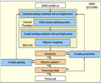
An automated process is proposed in this paper. It is described
in Fig. 5. The optimization variables are the six coefficients of the
modified roll method commonly used in the spiral bevel gear machining. These settings enable to precisely handle the contact path. The objective function to be minimized is the maximum contact pressure along the loaded contact path.
The process is driven by the application manager developed by Samtech: BOSS QUATTRO. The initial values of the optimization variables are imported from a pre-design software or a previous study. The optimization module runs external procedures which have been developed using a standard programming language to create the loaded meshing model, taking also into account the displacement of the gear axes. Then it launches the MECANO script which simulates the mechanism behaviour using the finite element meshes of the teeth and their positions provided by the external procedures. It gets back the value of the objective function. The variables are successively perturbed in order to evaluate their influence on the result and to estimate a combination of their values that should lead to an improvement. Each change results in a recalculation of the objective. The loop is iterated until reaching the convergence threshold of the objective function.
The FE model that is the heart of the process is shown in Fig. 6. Only three teeth of each part are considered. It is assumed that the loaded contact ratio is less than three teeth. Each node of the conical interface is connected by rigid bodies to the axis of the respective part. The relative position of the teeth due to load is reproduced by displacing the axes in accordance with the results of the whole FEM model described in Section 3. The boundary conditions of the simplified model are shown in Fig. 6. A torque is applied along the driving gear axis. The driven part axis is successively fixed at given angular positions.
The loaded contact simulation is based on a non-linear static analysis. The computation is done by the software MECANO. The initial meshing position gives a slight interpenetration of the two teeth in contact. It is the starting point of the iterative research of the static equilibrium of the system. The contact area is updated during the computation. It moves and spreads until the equili-brium is reached. The result is the starting point of the iterations for the next angular position of the driven gear. The algorithm solves the contact problem for each given meshing positions. 4.2. Application case
Data defining the example considered here are presented in the first six lines of Table 1. The second part of this table gives the values of the six coefficients of the modified roll method obtained after a manual optimization process. These six values are the starting point of the automated contact path improvement process.
The components of the relative displacement of the gear axes are deduced from a loaded FE analysis of the complete gearbox. They are given in Table 2.
The optimization process runs on a PC with 2 CPU clocked at 1800 MHz. It is stopped after about 7 h. No error is generated during the execution of the various modules, although a wide variety of configurations is considered. This confirms the robust-ness of the algorithms that have been developed [20].
The process progression is illustrated in Fig. 7. The convergence discontinuity observed results from the surface discretization. The pressure peaks are due to contacts on flank edges. Nevertheless, the overall trend shows a reduction of the maximum contact pressure. The gear specialist chooses the combination of values of variables which gives the best result. The optimal design is achieved here at the 21st iteration. Table 3 lists the related variables.
Fig. 5. New spiral bevel gear topography optimization process.
Table 1
Initial manufacturing data.
Workpiece Pinion Gear Tooth number Module Whole depth Addendum Face angle Pitch angle MR coefficient 1 MR coefficient 2 MR coefficient 3 MR coefficient 4 MR coefficient 5 MR coefficient 6 23 5 10.24 5.6 40.2 37.483 0.639404 ÿ0.005814 0.000598 ÿ0.000997 0.000023 ÿ0.000168 30 5 mm 10.24 mm 3.65 mm 54.283 8 52.517 8 0.794488 0 0.001704 0 ÿ0.000024 0 Table 2
Displacement compounds of the gear axes. Pinion axial displacement
Gear axial displacement Offset displacement Shaft angle displacement
0.441742 mm ÿ0.065310 mm ÿ0.401187 mm 0.005277 8 1 3 5 7 9 11 13 15 17 19 21 23 25 27 29 Iteration number O bje ct ive va lu e (M P a)
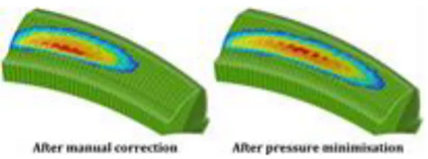
Use of wide mesh to discretize the teeth, as shown in Fig. 8, increases the speed of calculation. In return, the pressures are calculated with less precision. However, it is possible to make a comparative analysis based on models constructed with meshes of the same size. Fig. 9 shows a significant improvement in load sharing compared to manual correction. The contact pressure is 1985 MPa after manual correction and 1582 MPa after maximum
pressure minimization. Fig. 10 shows that the contact area is significantly extended, while avoiding the occurrence of a contact at the edges.
5. Conclusion
An optimization process able to design in an automated way the shape of spiral bevel gear flanks has been presented. It leads to a significant reduction of the development time, while allowing a strengthening of the quality of contact patterns by the reduction of the contact pressure. Its extension to the minimization of tooth contact errors seems possible, in order to contribute to the reduction of noise and vibration levels and therefore a higher durability of helicopter gearboxes.
References
´ ´
` ´ ´
´
´
[1] Mermoz E, Linares J-M, Bernard A (2011) Benefits and Limitations of Para-metric Design Implementation in Helicopter Gearbox Design Phase. Annals of the CIRP 60/1:199–202.
[2] D. Madrosky, Conception des engrenages spiro-coniques: Geometrie et simu-lation du comportement. These de Doctorat en Genie Mecanique, Institut National des Sciences Appliquees de Lyon, 1987.
[3] Gosselin C, Cloutier L, Nguyen QD (1995) A General Formulation for the
Calculation of the Load Sharing and Transmission Error Under Load of Spiral Bevel and Hypoid Gears. Mechanism and Machine Theory 30:433–450.
[4] Lelkes M, Marialigeti J, Play D (2002) Numerical Determination of Cutting Parameters for the Control of Klingelnberg Spiral Bevel Gear Geometry. Journal of Mechanical Design 124(4):761–771.
[5] De Vaujany J-P, Guingand M, Remond D, Icard Y (2007) Numerical and
Experimental Study of the Loaded Transmission Error of a Spiral Bevel Gear. Journal of Mechanical Design 129(2):195–200.
[6] Alves JT, Guingand M, de Vaujany JP (2010) Set of Functions for the Calculation
of Bending Displacements for Spiral Bevel Gear Teeth. Mechanism and Machine Theory 45:349–363.
[7] Bibel GD, Handschuh RF (1996) Meshing of Spiral Bevel Gearset with 3D Finite
Element Analysis. NASA TM-107336.
[8] Litvin FL, Fuentes A, Fan Q, Handschuh RF (2002) Computerized Design,
Simulation of Meshing, and Contact and Stress Analysis of Face-milled Formate Generated Spiral Bevel Gears. Mechanism and Machine Theory 37:441–459.
[9] Argyris J, Fuentes A, Litvin FL (2002) Computerized Integrated Approach for Design and Stress Analysis of Spiral Bevel Gears. Methods in Applied Mechanics and Engineering 191:1057–1095.
[10] Litvin FL, Fuentes A, Mullins BR, Woods R (2003) Computerized Design, Generation, Simulation of Meshing and Contact, and Stress Analysis of For-mate Cut Spiral Bevel Gear Drives. NASA CR – 2003-212336.
[11] Vimercati M (2007) Mathematical Model for Tooth Surfaces Representation of Face-hobbed Hypoid Gears and Its Application to Contact Analysis and Stress Calculation. Mechanism and Machine Theory 42:668–690.
[12] Simon V (2009) Head-cutter for Optimal Tooth Modifications in Spiral Bevel Gears. Mechanism and Machine Theory 44:1420–1435.
[13] Artoni A, Bracci A, Gabiccini M, Guiggiani M (2009) Optimization of the Loaded Contact Pattern in Hypoid Gears by Automatic Topography Modification. Journal of Mechanical Design 131:011008-1–011008-9.
[14] Bracci A, Gabiccini M, Artoni A, Guiggiani M (2009) Geometric Contact Pattern Estimation for Gear Drives. Computer Methods in Applied Mechanics and Engi-neering 198:1563–1571.
[15] Artoni A, Kolivand M, Kahraman A (2010) An Ease-off Based Optimization of the Loaded Transmission Error of Hypoid Gears. Journal of Mechanical Design 132:011010-1–011010-9.
[16] Kolivand M, Kahraman A (2009) A Load Distribution Model for Hypoid Gears Using Ease-off Topography and Shell Theory. Mechanism and Machine Theory 44:1848–1865.
[17] Gabiccini M, Bracci A, Guiggiani M (2010) Robust Optimization of the Loaded Contact Pattern in Hypoid Gears with Uncertain Misalignments. Journal of Mechanical Design 132:041010-1–041010-8.
[18] Mermoz E (2012) Benefits of Virtual Testing for Drive System Development. American Helicopter Society AHS, Austin, TX.
[19] Zamponi L, Mermoz E, Linares J-M (2011) Study of Bearing Modelling in the Helicopter Gearbox. Advanced in Power Transmission Sciences Book Series Applied Mechanics and Materials 86:721–724.
[20] Astoul J, Sartor M, Geneix J, Mermoz E (2013) A Simple and Robust Method for Spiral Bevel Gear Generation and Tooth Contact Analysis. International Journal on Interactive Design and Manufacturing 7(1):37–49.
Table 3
Values of the variables after pressure minimization. `
Piece Pinion
Modified roll coefficient 1 Modified roll coefficient 2 Modified roll coefficient 3 Modified roll coefficient 4 Modified roll coefficient 5 Modified roll coefficient 6
0.640054 ÿ0.005219 ÿ0.001244 ÿ0.000292 ÿ0.001435 0.000445
Fig. 8. Model mesh and contact areas.
Fig. 9. Load sharing before and after optimization.
![Fig. 4. Example of complex FEM models [18].](https://thumb-eu.123doks.com/thumbv2/123doknet/12207403.316505/3.892.145.332.274.407/fig-example-complex-fem-models.webp)