HAL Id: inria-00536949
https://hal.inria.fr/inria-00536949
Submitted on 17 Nov 2010HAL is a multi-disciplinary open access
archive for the deposit and dissemination of sci-entific research documents, whether they are pub-lished or not. The documents may come from teaching and research institutions in France or abroad, or from public or private research centers.
L’archive ouverte pluridisciplinaire HAL, est destinée au dépôt et à la diffusion de documents scientifiques de niveau recherche, publiés ou non, émanant des établissements d’enseignement et de recherche français ou étrangers, des laboratoires publics ou privés.
J.I. Jimenez, Manuel Lopez, P. Smyth, Giambattista Gennari, Davide
Raimondo, P. Donaggio, S. Gasparella, B. Lain, Jan Opderbecke, Luca
Schenato, et al.
To cite this version:
J.I. Jimenez, Manuel Lopez, P. Smyth, Giambattista Gennari, Davide Raimondo, et al.. FeedNetBack-D01.04 - Tool Specifications. [Contract] -. 2010. �inria-00536949�
Deliverable
D01.4
Nature
Report
Dissemination
Internal
D01.4 - TOOL SPECIFICATIONS
Report Preparation Date
31/07/2010
Project month: 24
Authors
J.I. Jimenez and M. Lopez (US), P. Smyth (OMG),
G. Gennari (VIDEOTEC), D. Raimondo (ETH),
P. Donaggio, S. Gasparella and B. Lain (VIDEOTEC)
J. Opderbecke (IFREMER), L. Schenato (UNIPD),
D. Simon (INRIA), T. Oechtering and C. Fischione (KTH).
Report Version
Vn 3
Doc ID Code
USP3_D01.04_31JUL10_V3
Contract Start Date
01/SEP/2008
Duration
36 months
Project Coordinator :
Carlos CANUDAS DE WIT, INRIA, France
Theme 3:
EXECUTIVE SUMMARY
FEEDNETBACK deals with problems arising in networked control applications, whose solution re-quires putting together the instruments of different disciplines, namely control theory, communication and information theory, and computer science. Each of these disciplines has its own characteristics in terms of problems that are typically faced, and in terms of the requirements which are typically desirable in the systems to be designed. Therefore, it is necessary to integrate in a software different functionalities in order to simulate correctly the behavior of the whole set.
This deliverable focuses on the different tool specifications which are proper in the simulators of each of these disciplines and significant in the class of problems considered in the present project. In this way, we first present a survey on available tools for each of these disciplines, in which we analyze the func-tionalities than can be used to simulate the behavior of networked control systems. Next, we explore how existing tools can be combined in order to provide different functionalities with good results. After this overview, we present a discussion about the guidelines for determining the tools functionalities related to control, communication and computation which make sense in networked control systems. Especially we focus on the case studies developed in work packages WP7 and WP8, respectively Smart camera networks for surveillance and motion captureand Application to underwater exploration by multi-agent systems. Finally, we determine the functionalities and specifications that will serve as guidelines for the tool development efforts of work packages WP2-5.
This report presents the functionalities and specifications of the computational tools that enable the simulation of networked control systems, and thus, the application of theoretical results. This document is an input to WP2-5 where the described tool set will be developed.
Contents
1 Introduction 4
2 Survey on available tools 4
2.1 Motivation and objectives . . . 4
2.2 General overview . . . 5
2.3 Extension of control-oriented simulators . . . 5
2.4 Extension of network-oriented simulators . . . 5
2.4.1 Extension of NS-2 . . . 6
2.4.2 Extension of Opnet . . . 7
2.5 Combination of Simulators . . . 7
2.6 Solutions Adopted for Networked Control Systems . . . 8
2.6.1 Non-complex networked control systems . . . 8
2.6.2 Complex networked control systems . . . 8
2.7 Conclusions . . . 9
3 Tool functionalities for case study 1: Smart camera networks for surveillance and motion capture 9 3.1 Project Development . . . 9
3.2 Control Architecture . . . 10
3.3 Overview of Software Developments . . . 10
3.4 Software Development for a Tracking Algorithm . . . 11
3.5 Software Development for Single Camera Calibration . . . 12
3.5.1 Introduction . . . 12
3.5.2 Calibration Parameters . . . 12
3.5.3 Assumptions and Constraints . . . 13
3.5.4 Procedure . . . 14
3.5.5 Technical Data and Test bed . . . 18
3.5.6 Conclusions . . . 18
4 Tool functionalities for case study 2: Application to underwater exploration by multi-agent systems 18 5 Functionalities and Specifications for the Tool Set 21 5.1 Functionalities and specifications for control and complexity tools . . . 21
5.1.1 Scaling. . . 21
5.1.2 Heterogeneity . . . 21
5.1.3 Time consistency . . . 22
5.1.4 Plug-and-Play . . . 22
5.2 Functionalities and specifications for control and communications tools . . . 23
5.2.1 Analog distributed source-channel coding using sinusoids ([37]) . . . 23
5.2.2 Optimized encoder-controller mappings for closed-loop control over bandlimited noisy channels ([33, 35, 36]) . . . 23
5.2.4 Rate-maximizing mappings for memoryless relaying ([39, 40, 41]) . . . 24
5.2.5 Rate-sufficient conditions for closed-loop control over AWGN relay channels ([42, 44]). 24 5.2.6 Coding of streaming sources for the bidirectional broadcast channel ([38]) . . . 24
5.3 Functionalities and specifications for control and computation co-design tools . . . 24
5.3.1 Tools needs for control and computation co-design . . . 24
5.3.2 The Orccad model . . . 25
5.3.3 Orccad tools . . . 28
5.3.4 Summary and perspectives . . . 29
5.4 Functionalities and specifications for energy-efficient embedded networks and control tools . . . 30
5.4.1 Analytical Modeling of IEEE 802.15.4 for Energy Efficient Networks ([50, 46]) . . . . 30
5.4.2 Optimization of IEEE 802.15.4 for Energy-Efficient Operations ([48, 49, 53, 51]) . . . . 30
5.4.3 Design of New Energy-Efficient Protocols for Control ([47, 52]) . . . 30
5.4.4 System Level Design of Controllers and Energy-Efficient Networks ([45]) . . . 31
6 Conclusions 31
1
Introduction
The analysis and design of networked control systems mainly relates three disciplines normally sepa-rated, namely the control theory, the communication and information theory and the computer science. This gap between disciplines has given rise to separate developments of different and very specific sim-ulation tools. Thus, currently there is no commercial simulator that integrates all the disciplines. The major benefit of such a unique tool for networked control systems would be the determination of detailed relations among the control and the network variables, and also would provide very useful information in order to design new control strategies and protocols.
This report first presents a survey on available tools for each of these disciplines, in which we analyze the functionalities than can be used to simulate the behavior of networked control systems. Next, we explore how existing tools can be combined in order to provide different functionalities with good results. After this overview, we present a discussion about the guidelines for determining the tools functionalities related to control, communication and computation which make sense in networked control systems, especially for the case studies developed in work packages WP7 and WP8, respectively Smart camera networks for surveillance and motion captureand Application to underwater exploration by multi-agent systems. Finally, we determine the functionalities and specifications that will serve as guidelines for the tool development efforts of work packages WP2-5.
2
Survey on available tools
2.1 Motivation and objectives
Simulation techniques are very useful in the study of complex systems, which is the case of networked control systems. The lack of specific simulation tools in this multidisciplinary context represents an im-portant obstacle for the analysis of such systems. The goal of this survey is to provide a simulation framework that enables the analysis and co-design of networked control systems, providing functionali-ties that current commercial tools do not offer.
2.2 General overview
Currently there are several commercial programs which are very good and useful for one specific discipline. In this way, on the one hand, there are very powerful tools for control simulation, which allow to describe the dynamics of systems in an intuitive and rather simple manner, providing an efficient way to analyze and design control strategies. As a very known example in this field, we can cite MatLab [1]. On the other hand, in the field of computer networks there are also several simulators used in the academia. Among them, the most important ones are ns-2 [2] and Opnet [3]. Both describe the event-oriented nature of communication networks and implement their behavior with great accuracy. The main problem with all these tools, is that they have been designed for a specific purpose in a closed framework (control theory or information sciences) and, in general, they are not easily extensible to other fields. Hence, since there are no tools to analyze the whole problem in networked control systems, the following solutions have been proposed so far:
• to extend control-oriented simulators in order to make them simulate the behavior of computer networks.
• to extend network-oriented simulators in order to make them simulate control systems.
• to introduce a co-simulation between a control-oriented simulator and a network-oriented one. 2.3 Extension of control-oriented simulators
The first solution consists of extending the simulation tool used for dynamical systems, in order to simulate events and the dynamics of the network. This option was chosen by the authors of the tool TrueTime [4, 5], which uses Simulink [6] as the simulation engine. TrueTime models the temporal behavior of the nodes in a network, as individual blocks in Simulink. This allows to connect the behavior of each node in a network by simply connecting the blocks, being rather easy to implement. Figure 1 shows some of the blocks added by TrueTime to Simulink.
However, TrueTime is not a complete network simulator and it is only useful under certain network scenarios. One of the most remarkable limitations of TrueTime is that only models local area networks. Thus, it cannot be used to model networks that include protocols of higher layers (transport layer and application layer). Besides, it has other limitations in the implementation of wireless networks [7]. The most remarkable one is that only the standard 802.11b is implemented. This standard, free since 1999, has been improved in later developments giving rise to the standards 802.11a, 802.11g y 802.11n. These new standards provides larger transmission rates, larger coverture range and better responses in noisy ambient. Hence, restricting the study of simulations just for WLAN 802.11b networks would be an important lack. Furthermore, TrueTime does not model the infrastructure mode. This mode fits perfectly with the idea of centralized control and cannot be neglected.
For all these reasons, we consider that extending the capabilities and functionalities of a control-oriented simulator is not the best choice for our purposes in the framework of networked control systems. 2.4 Extension of network-oriented simulators
Figure 1. TrueTime Network Blocks for Simulink.
those used in wireless networks (802.11). In its turn, Opnet is a commercial software, very used in the industry, which also enables to analyze a great variety of networks.
2.4.1 Extension of NS-2
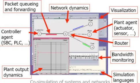
There exists an extension of NS-2 [8, 9, 10] that allows the integration of dynamical systems in network scenarios. This is done by using a new feature implemented by means of the denominated controller and plant agents. These agents enables to describe the dynamics of the systems using differential equations defined in NS-2. These differential equations are solved by external mathematical applications (Ode [15], Octave [16], etc.), since NS-2 does not feature this functionality. Figure 2 shows a network scenario in which a controller (agent) and three plants (agents) communicate among them through a wireless access point. Figure 2 has been also drawn by an external application since NS-2 neither has this functionality.
NS-2is built thanks to users’ contributions and developments, which are not normally subject to strict revisions. Thus, end users are responsible for checking thoroughly the models, since to obtain coherent results it is necessary a complete and accurate model of the network. NS-2 also has some limitations when modeling the standard 802.11, as indicated in [2], which are:
• Only the standard 802.11b is implemented.
• The Bit Error Rate (BER) is not taken into account when refusing packets. • The Backoff period is not correctly modeled.
• The infrastructure mode is not implemented.
Although there exist several particular contributions that solve some of these problems, none of them solves these drawbacks globally, and are not in general compatible among them. Besides, all this contri-butions still need to be validated.
Figure 2. NS-2: Graphical interface.
2.4.2 Extension of Opnet
Opnetis a commercial software that enables the simulation of a wide range of communication networks. With respect to wireless networks, it implements all the 802.11 standards: 802.11b, 802.11a, 802.11g y 802.11n. It also includes the modes infrasctructure and Ad-hoc. Besides, it provides very complete network models taking into account a large variety of performance details, which are normally ignored by the rest of network-oriented simulators.
Opnethas a modular architecture, and this make its extension easier. It also provides some advanced functionalities oriented to analyze results, as statistical computations (mean, variance, confident inter-vals, etc.) and graphical representation. Furthermore, it has an user’s interface very intuitive and easy to use. In [17] there is an interesting comparison with NS-2 with respect to their learning curves, showing that learning Opnet is easier than learning NS-2.
The main drawback of Opnet is that does not have direct tools to implement dynamical systems. Hence, it is quite difficult to develop simple control schemes which are very easy to implement when using tools like Simulink, or even to compute matricial operations which are easily done when using MatLab. However, since Opnet also can be programmed using C/C++ language, most of these problems can be solved with some programming work. Particularly, in [18] we extend the OPNET simulator in order to include process control, analyzing the range of interest for most 802.11 operational parameters when applied to control systems.
2.5 Combination of Simulators
The third approach consists of studying the possibility of using two specific simulators simultane-ously. This is referenced as co-simulation, and consists of running simultaneously a network-oriented simulator with a control-oriented simulator. The co-simulation enables to exploit the functionalities of both simulators without introducing any extension or adaptation in them. Hence, it provides a rich and
powerful framework, offering the largest number of possible functionalities. This option allows to sim-plify the simulation of networked control systems, since each problem is treated and simulated separately and in a modular way, reducing its complexity.
The major drawback of this approach is how to solve the communication between tools. In order to make a co-simulation possible, it is necessary to coordinate both simulators, and this requires, first, a communication interface and, second, a synchronization protocol. However, most simulators do not feature this interface. Thus, the study is constrained to a reduce group of simulators.
On the one hand, with respect to control-oriented simulators, just MatLab features a communication interface. There exist other simulators, like Modelica [10] and ADVS [19], which have been used jointly with other simulators, but in these cases the communication interfaces were developed by third parties (users). These interfaces were developed to work with a specific simulator and, in most cases, extensions to other simulators are not available.
On the other hand, in the case of network-oriented simulators, Opnet is the only tool which provides a well-defined communication interface that enables an external communication. In the case of NS-2, the communication with other simulators (MatLab) is possible but not the synchronization, which is a necessary condition for co-simulation.
Therefore, to the best of our knowledge there is only one possible combination of simulators to achieve the co-simulation purpose, and this is to use jointly Matlab and Opnet. This combination is the only one that enables a real co-simulation, taking advantage of all the functionalities present in control-oriented and network-oriented simulators.
However, although the co-simulation is possible using these two tools, another problem may arise when the scenarios to simulate are complex. Then, the performance of the co-simulation has to be taken into account to clarify the limits of this approach. For simple scenarios, the time needed to finish the simulation normally is not quite long. However, when simulating complex scenarios, the performance in co-simulation degrades, and the simulation time increases significantly.
In this project the scenarios to be simulated may be composed of dozens or even hundreds of so-phisticated sensors, multiple control systems and complex plants. In these scenarios the simulation performance is critical because a degradation would lead to unfeasible simulation times. For this reason, this option will be only used in the case of non-complex networked control systems.
2.6 Solutions Adopted for Networked Control Systems 2.6.1 Non-complex networked control systems
From section 2.5 we deduce that the best option to simulate the behavior of non-complex networked control systems is using co-simulation between MatLab and Opnet. In this case, the number of nodes in the network cannot be large in order to have a good performance.
2.6.2 Complex networked control systems
For the very general case, we have to assume that the number of nodes in the network will be large. In this case the solution proposed in 2.5 is not effective due to the high values of simulation time.
Then after analyzing the advantages and drawbacks of all the aforementioned options, we have found that the extension of the Opnet sofware, described in 2.4.2, is the most suitable one. The main reasons for such a decision are the following:
• Opnet has more accurate and actualized network models than the rest of simulators. • it also offers tools that enable to model dynamical systems and hence control systems.
• it has a modular architecture that enables the integration of new modules with the existent ones. All these features make Opnet the most appropriate tool for the analysis and design of complex net-worked control systems, which require very accurate network models and optimal simulation perfor-mance.
2.7 Conclusions
In this section we have compared several tools and explored their functionalities in order to be used as networked control systems simulators.
Since there is not a specific tool for analyzing and simulating complex networked control systems, three options has been studied: the extension of network-oriented simulators, the extension of control-oriented simulators and the combination of both. The tools explored at the moment has been Truetime (simulink), ns-2, modelica and Opnet-Matlab. The combined use of Opnet and simulink has reported the best results at the moment when the number of nodes to interconnect in the network is small. However, for a large number of nodes, the performance of the co-simulation, in terms of computational load and time, degrades. At the moment we continue working on that issue. On the other hand, another solution is to develop an extension of Opnet, since it offers programming tools (C/C++ Language) to simulate dynamical models, enabling the design of control strategies.
3
Tool functionalities for case study 1: Smart camera networks for surveillance
and motion capture
The aim of this case study is to evaluate algorithmic approaches regarding the coordination of a network of cameras in order to accomplish the thread of tracking subjects moving through an observed volume. The goal of this case study is then to motivate the theoretical questions to be addressed in WP1-5 and to serve as a testing ground for some of the developed methods and tools.
3.1 Project Development
For the sake of the project development, this case study is divided into multiple tasks, although these tasks are mutually dependent to each other.
1. Automatic Calibration: The calibration process provides the system with the information needed to perform the monitoring and tracking tasks.
2. Cooperative monitoring: Cooperative detection/monitoring is a coordinated search of anomalous events. For this task coordination is obtained moving the FOVs properly in order to maximize the overall probability of detection.
3. PTZ Tracking: After the calibration steps, when a moving object is detected, it must be followed be at least one PTZ camera1. Specifically, in the tracking process, the object should remain inside
the field of view of at least one camera as much as possible, at the maximum zoom level3. 3.2 Control Architecture
The control system consist of one local controller, or video agent, per camera. The video agent is a plug-in point for the academic partners to supply control algorithms. Video agents are capable of acting and communicating to each other in a decentralized fashion. In other words, not all video agent have (or need) the same information available, nor the same task. They can autonomously perform a task or cooperate with other video agents. Each video agent will be supplied with some static information in the factory, namely the camera internal parameters. Camera PTZ controllers cannot move arbitrarily quick. This has to be taken into account in the control algorithm design.
Scalability Even if the test bed is a small network of PTZ cameras, the system must be able to cope with very large scale areas as well, using the same control algorithms. The system should deal with cameras’ faults, dynamically reconfiguring itself with the available sensors. In order to cope with very large monitored sites, proper information management becomes compulsory: sensors should only share relevant information to smaller subset of VAs, depending on their own task, positioning and redundancy policies.
Communication and control co-design Because of the large amount of bandwidth consuming data that passes through the LAN (e.g.: video, audio, etc.), bandwidth requirements must be reduced as much as possible. This is even more important in large systems. For example, bandwidth requirements for a H264 compressed video are between 1 to 2Mbps. Moreover, data could be sent across multiple hops before reaching destination, causing serious delays. These delays are difficult to estimate. In this regards, VAs should exploit their decentralized approach in order to keep and share relevant information only with other VAs involved in the same task (for example, with neighboring VAs when performing target tracking).
Computational power and control co-design When the number of cameras or targets increases, the information to be processed and the complexity of the algorithms need to be managed properly, taking into account the limits in terms of computational power of each processing unit.
3.3 Overview of Software Developments
With the support of Videotec S.p.A., ETH has set up in its laboratory a test-bed comprising of two Pan-Tilt-Zoom Ulisse Compact Cameras. A tracking algorithm for PTZ cameras has been developed so far.
A software has been developed in order to detect and to track the targets. The main modules of such a software are:
1. blob and color detection: in this module, image frame are captured. In order to detect the blobs of the cars we have converted the images from RGB (Red, Green, Blue) to HSI (Hue, Saturation, Intensity) color space. Then, the blob detection has been obtained by applying the logical operator or to the S and I components of the images. Once blobs have been detected we compute the histograms for the hue component and by dividing the hue in ranges, we are able to distinguish between different colors and hence to identify the different targets.
2. Identification of unknown parameters: in this module camera extrinsic and intrinsic parameters are estimated. The camera calibration toolbox for Matlab of Bouguet together with the least squares method are used for the estimation. The module is used only once, in order to identify cameras parameters.
3. Targets model: in order to describe the dynamic behavior of the targets a unicycle model has been implemented.
4. EKF: extended Kalman filter predicts future targets position by linearizing the target model 5. Centering the predicted target position: an analytical solution for centering predicted target
posi-tion has been found and implemented.
6. Particle filters: since, at each time, PTZ cameras detect just a small portion of the entire environ-ment, and considering that object actions are unknown, there exists a certain probability of losing track of the targets. When this happens, in order to find them again, one can think of still using EKF in open loop prediction. Instead, we decide to use particle filters (PF).
7. Simulated annealing: in order to find the target when PF is used, pan and tilt angles are changed to maximize the probability of detection, i.e. to maximize the number of particles visible to the camera. Such problem is solved by using Simulated Annealing.
8. Camera communication: each cameras sends and receives data from a PC. The data that are sent to the camera are required angle positions while the real angle values are received from the encoders. All this modules have been implemented in MatLab and are currently being developed in C.
As a future step, a network of cameras will be considered. In order to deal with communication network issues, Optnet seems to be the most appropriate tool. In fact it deals with networks and has the capability of being programmed using C/C++ language.
3.4 Software Development for a Tracking Algorithm
OMG (Vicon) has now established the main experiment and detailed specification of the software framework we will develop with a view to our academic partners (ETH Zurich) developing a (potentially distributed) control algorithm.
The experiment consists of tracking multiple rigid objects with 3 or more markers attached to each, using a combination of static and pan-tilt (possibly eventually zoom) controlled cameras. There are also static ’beacon’ markers placed in the scene, which are additionally required to constrain the calibration of the Pan-tilt-Zoom (PTZ) cameras. These beacon markers are treated as a single rigid object whose
world pose is known to be fixed. The PTZ cameras are calibrated dynamically as part of the tracking procedure. This is described in FeedNetBack deliverable 7.01.
The system is to be set up with a procedure to calibrate the parameters (positions, orientations and in-ternal parameters) of the static cameras, positions of the beacon markers, and mapping between ’control parameters’ of the pan-tilt head and world pose of the PTZ camera.
This procedure is based on initially calibrating the static cameras and PTZ cameras in their ’zero’ positions, using a standard Vicon wand calibration procedure. We then ’exercise’ the pan-tilt heads to simultaneously learn the control parameter-pose mapping, and the positions of all the beacon markers.
The tracking procedure then consists of a loop between: • capturing the state of the world, in terms of:
– Object world poses.
– PTZ camera parameters, presentable as pose or control parameters. – Visibility of respective markers in each camera view.
– 2d measurements of each marker in each view, which can be compared to the field of view of each camera, and 2d tracking in each camera.
• make a control step, given the state of the world, and issue this as a command to the pan-tilt heads. The latency between these two steps can be kept to a low, constant number of frames.
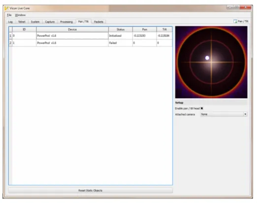
Vicon has set up and has written software to provide simple control of a specific, low-cost, pan-tilt head (PowerPod, made by Eagletron Inc.). We are developing the various elements required to build this tracking system. The GUI for this software is illustrated in fig. 3.
The process as described above is sensitive to tracking errors, and so improvements will be required to enable initialization of pan-tilt head pose if tracking is lost. This might be using pan-tilt head encoder information, or rigid object detection from a single camera view. This currently scales very badly with number of 2d points and object points, and is obviously much harder and ambiguous than the equivalent 3d problem. Most of the component algorithms have been completed, but there is still a significant level of integration work required to assemble the system and validate its behavior. We expect to have made significant progress on an early prototype by the 2nd year review.
3.5 Software Development for Single Camera Calibration 3.5.1 Introduction
In this section we present the Single Camera Calibration Algorithm developed by Videotec in the context of the European Project FeedNetBack. We do not want to underline here all the mathematical aspects of the algorithm but our effort is to emphasize the assumptions needed and the fundamental steps of the calibration procedure (See references [20, 21, 22, 23, 24] for more technical details).
3.5.2 Calibration Parameters
The Single Camera Calibration Algorithm identifies the unknown parameters of the camera - world model. In particular we want to estimate:
Figure 3. Graphical User Interface.
1. Heights of objects on the ground.
2. Distances between points on the ground.
3. Height, focal length and tilt angle of the camera.
All the information above will be used to improve the Detection and Tracking Algorithm developed by ETH and OMG.
3.5.3 Assumptions and Constraints
In order to make the problem feasible we made the following assumptions: 1. The environment has a visible ground plane.
2. The user of the graphical interface has to provide some information concerning the scene.
At he same time we do not want to simplify the problem too much so we added the following con-straints:
1. It is not possible to place any known object on the environment. 2. The information the user needs to provide is intuitive.
Figure 4. Height of reference objects given by the user.
3.5.4 Procedure
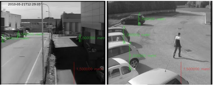
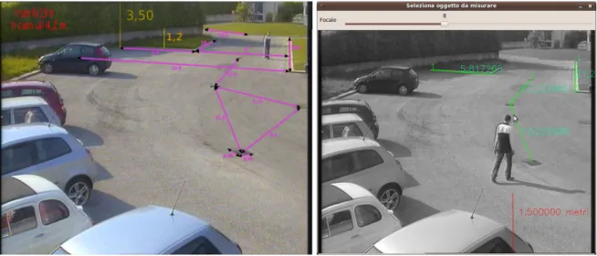
Heights of objects First of all the user has to point some heights of objects lying on the ground. Some examples are shown in fig. 4.
The green measurements selected by the user will be considered as reference objects. Thanks to this information we can compute the horizon line in a fully automated way. Figure 5 gives an idea of the basic formula.
Figure 5. Horizon line calculation
At the end of this part we are able to draw the horizon line on the picture.Once the horizon has been found and there are some reference objects, the user can pick something on the ground and the algorithm provides the height of the selection. The applied equations for this task are shown in fig. 6.
Figure 6. Measuring Height
The final output for the user is the one shown in fig. 7.
Camera’s Height With the previous information we are also able to compute the camera’s height in a automated fashion (See fig. 8.).
Figure 8. Camera’s Height
The heights can be displayed on the pictures and saved on a file.
Focal length and Distances If one of these parameters, the focal length or the tilt angle, is known, then it is possible to obtain the other one using a simple relation between them and then making 3d measurements using the model for the camera depicted in fig. 9.
Figure 9. Camera Model
Once the user has two 3d values on the ground is possible to compute the euclidian distance between them. Concerning this point there is an issue. In a real situation the operator doesn’t know the focal length of the camera or the Tilt angle, so it’s better using another procedure.
Procedure for the focal length The main steps are the following: 1. User selects a distance on the ground.
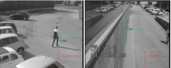
2. User moves a slide that changes the value of the focal length (See fig. 10). 3. User stops the slide when he gets a realistic value for the selected distance.
Figure 10. Focal Length Obtention
This visual feedback is really helpful for the operator that in this way is able to select a focal length really close to the real value. The Tilt angle and other distances on the ground are the outcome of the previous applied model plus the focal length. It’s also allowed to select a distance and then set manually a possible value without moving the slide, in this way the computation of the focal length is automatic. In fig. 11, there is an example of ground-truth and relative ground distances obtained with our approach.
Figure 11. a) Ground truth. b) Our approach
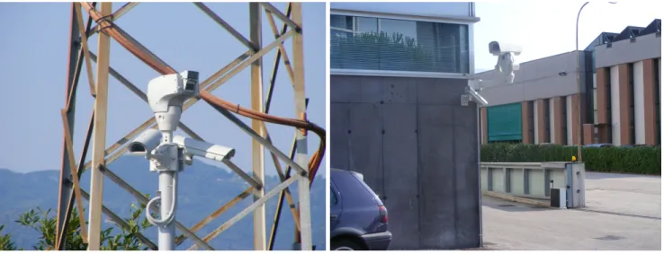
3.5.5 Technical Data and Test bed
The Single Camera Calibration Algorithm has been developed under the following features: • OS: Linux Ubuntu 9.04.
• Programming language: C.
• Library: computer vision library Opencv developed by Intel. • Drivers frame grabber: Matrox Imaging Library MIL Lite 9.
The final demo will be done on an outdoor environment, in the set up shown in fig 12.
Figure 12. Outdoor Test Bed
3.5.6 Conclusions
In this brief report we have described the procedure for the Calibration of a Single Camera. We have underlined the main aspects and in particular which are the steps that a operator has to do if he wants to use the proposed algorithm. Finally we want to mention that is really important how the operator selects the objects and sets the values. Due to the method is pixel-based, if we want to obtain good results the operations have to be done carefully, this means that the procedure takes time.
4
Tool functionalities for case study 2: Application to underwater exploration
by multi-agent systems
The aim of this case study is to evaluate algorithmic approaches regarding the coordination of a fleet of autonomous underwater vehicles (AUV) in order to accomplish complex tasks. The coordination of a group of 2 to 6 vehicles is based on information exchanged between vehicles over an acoustic data transmission device. This communication technique, which uses the only today exploitable physical transmission channel in the underwater environment, underlies very specific constraints in terms of
bandwidth, range, delay and the risk of packet loss. It is especially challenging to set up a network control scheme through such an underwater acoustics communication link, given that there is no duplex transfer possible.
The fleet coordination is considered in a distributed approach; every AUV will integrate as much information as it can gather from its partners. The navigation strategy is then implemented by every AUV itself. On the fleet coordination level, each vehicle has recurrent access to data gathered by the other AUVs on behalf of their environment; the vehicles will know what the mission strategy is at the fleet level, they will have knowledge of the relative position of other fleet members, and they will compute their proper motion commands with respect to the situation they perceive of the fleet and of the environment.
A technical simulator is under development in order to run benchmarking simulations of sampling and fleet coordination strategies:
1. The vehicles are simulated by a simple kinematic model with constant acceleration for translation in three axis and constant angular velocity for three axis rotations. This model is considered sufficient for formation control. These simulated AUV evolve in the same temporal and spatial context, suitable for coordinated mission strategies. An optional full dynamic model can be run with the vehicle controller of Ifremer’s asterX AUV in the simulation loop. This complex AUV model suits various simulation purposes and seems of only punctual interest for the fleet control problem.
2. The communication between AUVs is simulated through a synthetic acoustic model; in function of environment conditions and range, a signal strength is provided. The receiving vehicle sim-ulator then decides whether a data packet is received or rejected; The packet length and delay characteristics of acoustic signals propagating in sea water are respected.
3. The case study of WP8 considers sample strategies in an environmental problem. The environment simulator produces sensor data relative to spatial maps, like salinity, temperature, current etc. Within this representation of the environment, the fresh water source can be modeled by a plume of salinity concentration.
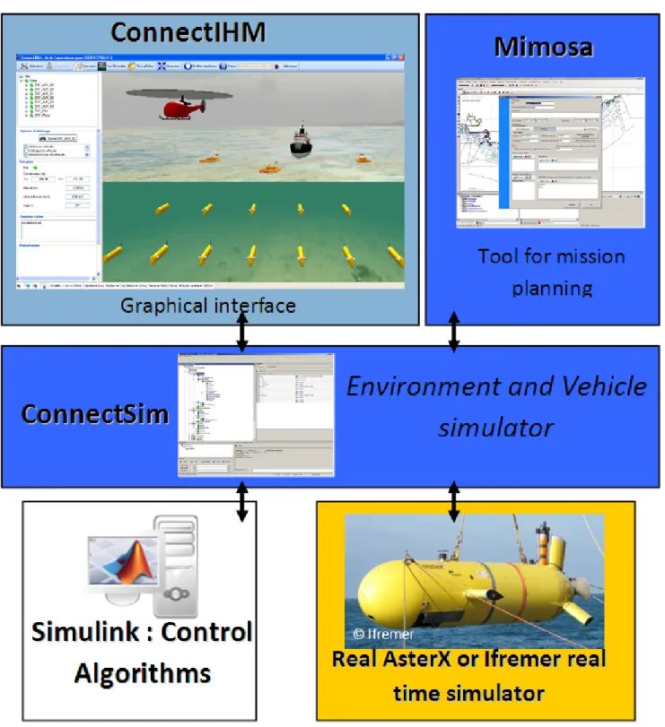
The aim of the simulator is to define an environment, an AUV fleet, and an objective or mission for the fleet. When executing, the simulator will broadcast the vehicle data on the network, and it will receive commands in an appropriate network protocol from any external software model. In this way, piloting strategies developed by partners of the FeedNetBack consortium can implement algorithms on a computer end software frame of their choice, and pilot the simulated AUV fleet via the network.
Figure 13 shows the simulator, which has is adapted from work accomplished in the French Research Agency (ANR) funded project CONNECT (http://www.lag.ensieg.inpg.fr/connect/). The simulator is designed in a modular architecture with a central communication server ConnectSim, a hardware-in-the-loop simulator of an Explorer AUV (Ifremer), an environment simulator (seabed, topography, salinity, temperature etc.) a Matlab/Simulink based fleet control, a 3D graphical visualization (ConnectIHM) and the mission planning tool Mimosa.
The fleet control block will host independent modules developed by FeedNetBack partners. Such modules issue commands for all AUVs of the fleet, allowing creating and maintaining formations, and leading to a sampling approach as solution to the fleet’s mission goal.
According to the case study expressed in WP8, a fresh water source is modeled in a given location, and a plume of progressively low salinity is defining the simulation environment. A sensor model produces a realistically noisy observation of the salinity for the location in x,y,z of each AUV. These sensor readings are transmitted through the ConnectSim communication server to the fleet controller, by implementing the characteristics of delay, signal absorption (risk of packet loss in the networking communication scheme which determines the rate of data transmissions.
By this concept we achieve the project test-bed for multi-vehicle control using unreliable and low rate data exchange.
5
Functionalities and Specifications for the Tool Set
During these two years, several software functionalities have been used and added in order to simulate some of the theoretical results achieved so far. In this section, we briefly enumerate and describe the current state of such software specifications.
5.1 Functionalities and specifications for control and complexity tools
The major difficulties that have to be faced for the development of simulative and design software tools arise from three problems: the scaling due to the large number of independent systems that have to be simulated, the potential heterogeneity among the different systems and the necessity to have a consistent notion of time. We now address them in detail.
5.1.1 Scaling
In Networked Control Systems it is common to deal with systems composed from a hundred to a thou-sand of devices with autonomous computational, communication, sensing and decision capabilities, that are often referred as "agent". In many areas, such as in Wireless Sensor Networks (WSNs), these agents are identical, i.e. they not only have the same hardware but they often the same software, i.e. the code stored on each agent is identical and only the interaction with the environment distinguishes their be-havior. These nodes can be static or mobile and communication is based on physical proximity. When trying to simulate these systems, one of the most important aspects is to understand their behavior as a function of their topology. Therefore, ideally we would like a software tool where it is possible to specify the behavior of an agent and then specify the connectivity graph. At present, with MATLAB/TrueTime, one has to create a single agent and then copy it as many times as needed and then interconnect them according the the desired topology. This is extremely time consuming. Besides, the simulation times becomes unbearably long when few dozens of agents are simulated.
Ideally, we need some dedicated software simulation tools specifically designed for identical agents, i.e. agents that have the same input/output interfaces and run the same software. This software should exploit this feature to speed up simulation times and to ease the designer to focus more on the topology and single agent code that should be immediately replicated in all agents present in the simulation. 5.1.2 Heterogeneity
different cameras are present. These agents have different resources, different sensors and actuators, and different objectives. Very often the typical architecture within these applications is hierarchical but dynamic and adaptive, i.e. different agents dynamically elect the leader or they dynamically gen-erate the interconnection topology. Simulating these systems is particularly challenging because of the heterogeneity.
One potential strategy to reduce this burden and to reduce programming time and simulation time, is to create a sort of "parameterized" agents specifically designed for a general class of applications which include a set of general parameters that need to be set depending on the specific task. For example, if the application under investigation is multi-vehicle coordination the parameter could be the equation for the dynamics, the actuator inputs, the sensor outputs, the objective function, the speed of the processor, the communication data structure, the communication medium and modem, etc...
5.1.3 Time consistency
In simulating a large number of independent agents, one of the most important problems is to maintain time-consistency among the different blocks. In fact, although each agent could potentially be simu-lated by a different computation unit, it is necessary that time-based actions and event-based actions are consistent. For example each agent has a number of operations that perform based on its own clock (time-based actions), such as communicate position periodically, and other operations based on the in-teraction with the environment (event-based actions), such as communicate when sensor measurement exceeds some threshold. Since local clocks have different speeds and many events are stochastic, i.e. present some unpredictable variability, it is not easy to simulate a large scale system. In particular all events should be scheduled in advance, but as explained, event-based actions can change the future schedule, and different realizations of the stochastic variable can give rise to rather different behavior. In addition, if the control strategy is strongly dependent on a synchronized set of actions of the agents, any mismatch can lead to catastrophic simulations not due to the control algorithm per-se but due to poor simulation.
It is not clear how this problem can be solved affectively. One natural strategy is to first simulate the local clocks relative to a fixed reference clock, and then order the (possibly stochastic) events with respect to the absolute time. Then, if an event-based action occurs which changes the predicted schedule, then a new schedule needs to be set from that event to the future. This is however, very inefficient and would lead to very long simulations times even for few agents. Better strategies should be devised, in particular if multi-processor simulations where each processor simulate a fraction of the agents to speed up simulation time, since time-consistency needs to be enforced.
5.1.4 Plug-and-Play
Another emerging paradigm in Network Control Systems is the design of systems of subsystems where the subsystem/agent can join or leave the network. This is also referred as plug-and-play control where the number of agents (sensors,actuators, controllers) is not fixed in advance but can be varied. This means that when creating a simulator for these systems, it should be possible for the designer to plug or unplug different subsystems during the simulation to study the effect. This can be a problem as many simulators require the compilation of the simulation code up front and then only limited actions can be taken at simulation-time.
Even in this case, some sort of modularity of the different agents should be exploited to ease evaluation of plug-and-play control. Besides plug-and-play control can be effectively used also to study agent failure or faults, since they can be modeled as systems that unplug from the network, or as a functioning agent that unplugs itself from the network and a malfunctioning agent that is plugged into the network. 5.2 Functionalities and specifications for control and communications tools
5.2.1 Analog distributed source-channel coding using sinusoids ([37])
In various closed-loop control applications there is a need to gather measurements from remote sensors. We have looked at two related problems within this area, namely, source coding of spatially correlated sources and multi-hop transmission, where the communication is aided by a relay. In both cases there is side-information available that can be used to reduce the transmission power significantly. We have pro-posed methods for designing low-delay sensor encoders and decoders. Generally, to design the encoders we require that the channel quality, which is typically characterized by the signal-to-noise ratio, and the source correlations are known. The design algorithms are based on iterative optimization and parameter optimization techniques. To evaluate the performance, we have implemented the algorithms using C++ and MATLAB. MATLAB has also been used to visualize the results and obtain deeper insights in how to optimally design source encoders.
5.2.2 Optimized encoder-controller mappings for closed-loop control over bandlimited noisy channels ([33, 35, 36])
We considered a joint design of the coding and control for linear plants, whose state feedback is trans-mitted over a rate-limited noisy channel. The system performance was measured by a finite-horizon linear quadratic cost. Two types of communication channels were considered: the binary symmetric channel and the binary input Gaussian channel. Iterative optimization techniques was used to train the encoder–controller pairs, taking channel errors into account in the quantizer design. Dynamic program-ming was used in the optimization of the controller mapping, and approximate dynamic programprogram-ming were used in the optimization of the encoder mapping. For binary input Gaussian channel, Hadamard techniques were adopted in the implementation of the controller. We have implemented the algorithms in MATLAB to examine the performance of the proposed coding–control scheme.
5.2.3 Optimized rate allocation for closed-loop control over bandlimited noisy channels ([34])
How to optimize the use of resources to provide sustained overall system performance is an important aspect in networked control systems. We have looked at the allocation of the communication rate (power) over a finite horizon for control over noisy channels. The system performance was measured by a linear quadratic cost. High-rate quantization theory was used to explicitly express the cost function in terms of the instantaneous rates. Then, the constrained optimization problem was solved by using Lagrangian techniques. We have implemented the algorithms in MATLAB to examine the performance of the proposed rate allocation scheme.
5.2.4 Rate-maximizing mappings for memoryless relaying ([39, 40, 41])
The instantaneous memoryless relaying is suitable for delay sensitive remote control applications. In this work we proposed the design of memoryless (single-input single-output) relaying strategies to max-imize the reliable transmission rate from the information source to the destination over Gaussian chan-nel. We used fixed-point iteration method to numerically optimize the relay mappings. This iterative optimization algorithm has been implemented in MATLAB, where we specify the following inputs: i) probability distribution of the source, ii) the average relay power, iii) the signal to noise ratio of the three links (source-destination, source-relay, relay-destination), and the iv) desired degree of accuracy in the optimized mappings (which is directly related to the number of iterations in the algorithm i.e., for a higher accuracy the algorithm requires more iterations). After the desired accuracy level is reached, the algorithm stops and we obtain a rate-optimized relay mapping for the given source, relay, and channel parameters.
5.2.5 Rate-sufficient conditions for closed-loop control over AWGN relay channels ([42, 44])
We considered the problem of remotely stabilizing a noiseless first order LTI plant over an orthogonal half-duplex and a non-orthogonal full-duplex AWGN relay channels. We assumed average power con-straints on the encoder and the relay and an instantaneous amplify-and-forward relaying scheme which is suitable for delay-sensitive closed-loop control applications. For the transmission of the observed plant states over the given relay channels, we used a Schalkwijk-Kailath coding scheme and therefore derived sufficient conditions for mean square stability. Our results reveal a fundamental relationship between the relay channel parameters i.e., the signal to noise ratio of the three links (encoder-decoder, encoder-relay, relay-decoder) and the possibility of stabilizing the unstable plant.
Similar fundamental rate sufficient conditions were derived in [ZOS10a] for networked control prob-lems using a multiple access channel and broadcast channel.
5.2.6 Coding of streaming sources for the bidirectional broadcast channel ([38])
We considered a problem of sequential coding where messages arrive as bit-streams to the encoders which could describe the evolution of two plant states. The plant states are observed by one node (observer) each and both by a central node (joint observer) which wants to make the other plant state known to the other node (controller where the action depends on other plant state). At the decoder side anytime decoding was required. Using random coding method we showed that the average bit error probability decays exponentially in delay with positive exponent for all the rate pairs inside the capacity region. Further, we showed the existence of deterministic codes which achieve exponentially decaying bit error probability with delay. These fundamental results show the theoretical existence of such codes and therefore could serve as a reference for practical designs.
5.3 Functionalities and specifications for control and computation co-design tools 5.3.1 Tools needs for control and computation co-design
Control and computation co-design deals with the interaction between feedback control laws design and their implementation on a real execution resource. Control design is often carried out in the framework of continuous time, or under the assumption of ideal sampling with equidistant intervals and known
delays. Implementation on a real-time execution platform introduces many timing uncertainties and distortions to the ideal timing scheme, e.g. due to variable computation durations, complex preemption patterns between concurrent activities, uncertain network induced communication delays or occasional data loss.
As already stated traditional, the observation and characterization of implementation induced dis-tortions on feedback controllers is usually beyond the capabilities of traditional simulation tools like Matlab/Simulink or Scilab. These lacks have motivated the deployment of specialized toolbox, such as TrueTime [30], to integrate models of operating systems and networks inside control dedicated existing simulation tools. As these tools provide modelers they can be used for fast prototyping and problems spadework.
However these approaches remain simulations and are still quite far from real implementation: models can be only abstractions of reality, and the code generators associated with these tools usually only provide elementary data structures and timing patterns which are not flexible enough to handle exotic implementations, e.g. feedback scheduling.
Another drawback is slow simulation speeds due to complex models involving a mix of continuous and discrete dynamics, that can be a handicap to study realistic scenario. On the other hand it appears that hardware-in-the-loop simulation (merging the real hardware/software targets and a simulated plant) is able to provide faster (real-time) simulations and is a useful last step before integration and tests on a real system.
In this section we present a new Integrated Design Interface dedicated to the design and implemen-tation of real-time control software, which has been developed based on the already existing ORCCAD
tool. ORCCAD is an integrated development environment aimed to bridge the gap between advanced
control design and real-time implementation [28, 25]. 5.3.2 The Orccad model
ORCCAD (Open Robot Controller Computer Aided Design) is first a model dedicated to the design and
implementation of real-time controllers. It uses existing theory (Control and Discrete Events theory) in accordance with software tools based on existing software technologies already used in the embedded and real-time domains (RTOS, Object Oriented Language, Synchronous Language,...).
It is also a Computer-Aided Software Engineering (CASE) tool dedicated to model and generate a fully featured ORCCAD based controller. To implement the CASE tool, the ORCCAD control model is abstracted using Eclipse Modeling tools based on Model-Driven Engineering (MDE) concepts and Open Source software components.
The formal definition of a control action is a key point in the ORCCADframework. Note that ORCCAD
rooted from robot control, so that many terms still refer to robotics: however the underlying concepts easily fit with other domains using control.
ORCCAD proposes a bottom-up approach, based on a stack of models to hold the design process
from elementary functions up-to complex application. Orccad is structured mainly according to two abstraction levels :
• The data flow control level provides the elementary tasks to produce the feedback control loops. This level is modeled through the notion of Robot Task that is a cyclic data flow algorithm managed by an event-based logical behavior.
• The discrete events control level aims at combining the elementary tasks in a logical way to define a robotic application or mission. This level is modeled through the notion of Robot Procedure. Control Tasks
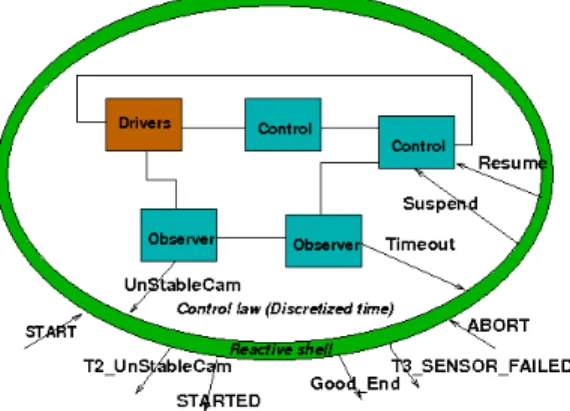
The Robot-Task (RT) models basic control actions, where feedback control aspects are predomi-nant. For example, let us cite hybrid position/force control of a robot arm, visual servoing of a mobile robot following a wall or constant altitude survey of the sea floor by an underwater vehicle. The RT characterizes in a structured way closed loop control laws, along with their temporal features related to implementation and the management of associated events as depicted in Figure 14 ([29, 31]).
Figure 14. Control task model
The feedback-control data flow is made of a connected acyclic graph of functions. Temporal con-straints are associated with the data flow to allow for real-time code generation. The control data flow is encapsulated in an event-based logical behavior (or abstract view), where events are structured with the following types :
• preconditions, which can be associated with measurements and watchdogs
• synchronization signals reports the occurrence of a particular state to synchronize different control activities;
• exceptions belong to different classes (weak, strong and fatal), they allow for the scheduling of control tasks, mode changes and recovery handlers activation;
• post-conditions are emitted when the control task successfully terminates.
Feedback control laws design: A RT is set-up by an acyclic graph of connected modules (i.e. functions), that are linked together via input/output ports to give a specific control loop, e.g. as in Figure 15. Modules follow a systematic structure : init() is run once, it is used to initialize the data and resources used by the function, compute() is executed cyclically when released by a synchronization event and end() is executed once at the end of the control task to free the used resources. This generic structure allows for cleanly initialize, stop, restart and terminate the control functions along the life of the control application.
Figure 15. A control task diagram
Modules can exchange data only through I/O ports, and oriented links define data dependencies and synchronization between modules. Ports are typed and specialized to support data exchange between functions, parametrization of modules, signalling events and exceptions and calling the drivers which interface the controller with sensors and actuators.
Temporal Constraints: The module specification defines an action from a continuous time point of view. Implementation related features are associated by setting run-time properties to modules glued inside temporal constraints, i.e. sampling rates, priorities, associated CPU, synchronization sources and user’s defined run-time policies, e.g. exception processing in case of overruns. The set of temporal properties associated with a set of connected modules sharing the same constraints is modeled by a Temporal Constraint (TC). The set of chosen attributes is assumed to be compliant with the API and features of most off-the-shelf operating systems with real-time capabilities (e.g. Posix). The main currently available run-time features are:
• Modules can be triggered by clocks, out-coming data from a port or external events;
• The underlying operating system is assumed to provide support preemption and priority based multitasking;
• Support is provided for multi-rate/variable rate data processing, non-blocking data integrity be-tween asynchronous activities is provided;
Supervision layer
the interface of a RT with its environment in a clear way, using typed input/output events, allows the composition of them in an easy way in order to construct more complex actions, the Robot-Procedures (RPs).
The RP paradigm is used to logically and hierarchically compose RTs and RPs in structures of in-creasing complexity. Usually, basic RPs are designed to fulfill a basic goal through several potential solutions, e.g, a mobile robot can follow a wall using predefined motion planning, visual servoing, or acoustic servoing according to sensory data availability. RPs design is hierarchical so that common structures and programming tools can be used from basic actions up to a full mission specification.
These well defined structures associated with synchronous composition, thanks to the use of the ES
-TEREL language [27], allows for the systematization and thus automatizing the formal verification on
the expected controller behavior. This is also a key to design automatic code generators and partially automated verification. Formal definitions of RPs and RTs together with associated available formal verification methods may be found in [29].
5.3.3 Orccad tools
The Eclipse Modeling Project (EMP) is the base for the model driven software development. It’s a tech-nology dedicated to build Domain Specific Languages (DSLs), where the structure of a DSL is captured in its meta-model. The meta-model is further used through various tools, such textual or graphical edi-tors, code generators or validation tools. The Eclipse IDE has the advantage to provide appropriate tools to produce binary executable from the generated source, for example the CDT (C/C++ development Tools) or debugging tools. This single environment includes all the tools needed to compile from model to binary executable.
Based on the ORCCAD meta-model, the tool suite of Figure 16 has been developed using Eclipse
packages and plugins. It is composed of:
• a text editor based on EMF and a graphical block-diagram oriented editor based on GMF allows for the specification of feedback control laws;
• a constraints specification tool based on the OCL language allows for the verification of the con-formity of the designed controller with the model;
• code generation uses the XPand package to generate C++ code for the feedback control specifica-tion, ESTERELcode for the discrete events supervision level and HTML for automatic
documen-tation.
Once a control application has been fully defined and parameterized, run-time code can be generated thanks to the models used all along the design process. It is assumed that the execution is supported by an operating system with real-time capabilities, and the system calls used in the ORCCAD model were
chosen to be generic enough to be found in most available RTOS. As control design is abstracted from any particular real-time target, the code generator provides the C++ code of the particular application, generated from the classes of modules, TC, RT and RP, together with the glue code to connect the end-users specific modules with the operating system.
At compile time this code is linked with a target specific run-time library used to bind the virtual system calls to real ones. Current targets are Linux (using Posix threads) and Xenomai (native API), porting on other Posix compliant systems can be easy and fast. It is also planned to port the run-time
Figure 16. Eclipse Modeling Project tools suite – Run-time architecture
library on some of the small operating systems dedicated to sensors networks, such as FreeRtos and/or Contiki.
The multi-tasking/multi-rate capabilities of the system have been already experimented with flexible controllers, e.g. as in [32] to experiment feedback scheduling on a robot controller. Fault tolerant control also took benefit from the exception handling capabilities of the system as in [26] where a hardware-in-the-loop simulator has been easily set up once a run-time has been generated. This later experiment also allowed to sketch applications using networked control systems.
Although provision is given at design time to assign real-time tasks to processors, up to now run-times are mainly generated for single CPU targets. When supported by the underlying real-time operating sys-tems and available API features, a multi-core implementation can be easily specified and generated, e.g. using the Linux pthread CPU affinity capability. Distributed controllers have been already prototyped, thanks to some additional hand coding using communication libraries based on UDP and CAN sockets. The deployment of controllers on a distributed/networked target is planned to be partially automated in future releases: anyway providing the distribution directives to the system will remain the duty of the designer.
5.3.4 Summary and perspectives
ORCCAD proposes a model to structure real-time supervised feedback controllers. Reusing the already existing and fruitful Orccad model, a new Integrated Design Interface dedicated to the design and imple-mentation of real-time control software has been developed based on modern tools. It allows to work out all the steps of control design, from elementary functions specification until run-time code generation, inside the coherent framework provided by Eclipse.
The new modeling framework is entirely based on open-source or freely available tools, powerful editors and software management process. Therefore, even if the current experience with this software is limited, it is expected that feedback from experience and new features requirements could be easily
and safely integrated. See http://orccad.gforge.inria.fr for further details and availability. 5.4 Functionalities and specifications for energy-efficient embedded networks and control tools
5.4.1 Analytical Modeling of IEEE 802.15.4 for Energy Efficient Networks ([50, 46])
Analytical modeling of the functionalities provided by the IEEE 802.15.4 Medium Access Control pro-tocol (MAC) for both single-hop networks and multi-hop networks was investigated. A generalized analysis of the IEEE 802.15.4 medium access control (MAC) protocol in terms of reliability, delay and energy consumption was investigated for single-hop networks. The IEEE 802.15.4 exponential backoff process was modeled through a Markov chain taking into account retry limits, acknowledgements, and unsaturated traffic. Simple and effective approximations of the reliability, delay and energy consumption under low traffic regime were proposed. It was demonstrated that the delay distribution of IEEE 802.15.4 depends mainly on MAC parameters and collision probability. In addition, the impact of MAC param-eters on the performance metrics was analyzed. We proposed a generalized analysis of the unslotted IEEE 802.15.4 MAC is for multi-hop networks. The model considered heterogeneous traffic and hidden terminals due to limited carrier sensing capabilities, and allowed to investigate jointly IEEE 802.15.4 MAC and routing algorithms. To define functionalities and specifications for software tools, analytical modeling of protocol behavior is essential. Once these analytical expressions are available, then the expression provided can be used to define functions and provide specifications. This research activity al-lows defining functionalities and specifications that IEEE 802.15.4 network simulators should be able to provide. The investigated analytical expressions of energy, reliability and delay can be used as functions to be invoked by network simulators. The input parameters for these expressions give specifications that the tools will have to include.
5.4.2 Optimization of IEEE 802.15.4 for Energy-Efficient Operations ([48, 49, 53, 51])
We investigated a novel approach to define IEEE 802.15.4 Medium Access Control (MAC) protocol functionalities and specifications based on a IEEE 802.15.4 protocol engine library. Current way of specifying MAC protocols for some application is based on two steps: the application specifications (such as network topology and packet generation rate) and requirements for energy consumption, delay and reliability, and the resource constraints from the underlying physical layer (such as energy consump-tion and data rate) are imposed. Second, the protocol funcconsump-tionalities that satisfy all these constraints is specified. Main drawback of this procedure is that we have to restart the design process for each possible application, which may be a waste of time and efforts. The goal of a MAC protocol engine is to provide a library of protocols specifications together with their analysis such that for each new application the optimal protocol functionality is chosen automatically among its library with optimal parameters. We illustrated the implementation of MAC protocol engine in the software framework called and then val-idating the analysis and demonstrating how to choose the optimal protocol under different application scenarios via the implementation in TinyOS.
5.4.3 Design of New Energy-Efficient Protocols for Control ([47, 52])
Control applications over energy efficient wireless sensor networks (WSNs) require timely, reliable, and energy efficient communications. We proposed a complete definition of functionalities of a new pro-tocol called TREnD based on a cross-layer optimization to exploit the complex interaction among the
layers of the protocol stack and reach a maximum efficiency. Such a design approach was challenging because reliability and latency of delivered packets and energy are at odds, and resource constrained nodes support only simple algorithms. The protocol was introduced for control applications over WSNs in industrial environments. It is a cross-layer protocol that embraces efficiently routing algorithm, MAC, data aggregation, duty cycling, and radio power control. The protocol parameters were adapted by an optimization problem, whose objective function is the network energy consumption, and the constraints are the reliability and latency of the packets. TREnD uses a simple algorithm that allows the network to meet the reliability and latency required by the control application while minimizing for energy con-sumption. TREnD was implemented on a test-bed written in TinyOS and NesC and compared to some existing protocols. Experimental results showed good performance in terms of reliability, latency, low duty cycle, and load balancing for both static and time-varying scenarios. The functionalities specified by the TREnD protocol can be included in a library of protocols and be part of a network simulator. 5.4.4 System Level Design of Controllers and Energy-Efficient Networks ([45])
There is not yet any systematic study of functionality and specifications for control systems networked by existing networking protocols for wireless sensor networks (WSNs). We studied the specifications in terms of stability of IEEE 802.15.4 networked control systems (NCSs). While in recent works from the literature fundamental results are developed for networks that are abstracted only in terms of packet loss and time delays, we considered the specifications imposed by the protocol to the feedback channel and the network energy consumption. A general analysis of the functionalities that a controller must pro-vide for linear systems with parameter uncertainty and external bounded disturbances with control loops closed over IEEE 802.15.4 networks was proposed. To reduce the number of transmissions and thus save energy, a self-triggered control strategy was used. A sufficient stability specification was given as func-tion of both the protocol and control parameters. It was shown that stability is not always guaranteed, unless protocol parameters are appropriately tuned. The functionalities of a decentralized algorithm to adapt jointly the self-triggered control and the protocol parameters were proposed. Simulation results illustrated the behavior of the control system algorithm and showed the reduction of the energy con-sumption, thus concluding that a system-level design of control systems and communication protocols is essential for NCSs over WSNs.
6
Conclusions
In this report we have considered the problem of determining the functionalities and specifications for the software tools development which are suitable for the networked control systems.
The difficulty of this task arises from the fact that networked control applications naturally concern problems in which control theory, communication theory and computer science play a role. As a con-sequence, the heterogeneity of such disciplines, and in particular the great difference in the software tools used in the various research communities, make necessary a deep study of them to extract what functionalities and specifications are needed for the networked control systems.
The proposed strategy has been to start with a survey on available tools for each of these disciplines, in which we have analyzed the functionalities needed to simulate the behavior of networked control systems. After this overview, we have analyzed the case studies deeply in order to have a plot of the general specifications that are needed. Finally, in order to give an input to work packages WP2-5, we