Subproblem finite element method for magnetic model refinements
Texte intégral
Figure


Documents relatifs
We present in this paper a pressure correction scheme for the drift-flux model combining finite element and finite volume discretizations, which is shown to enjoy essential
A thin shell solution, supported by a simplified mesh near the thin structures, serves as a source of a correction problem with the actual volumic thin regions alone in a
Analyses of magnetic circuits with position changes of both massive and stranded conductors are performed via a finite element subproblem method.. A complete
Abstract Model refinements of non-linear magnetic circuits are performed via a finite element subproblem method.. A complete problem is split into subproblems
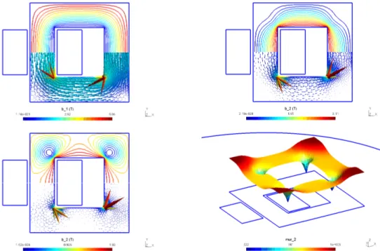
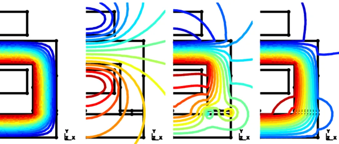
Field lines (top) and magnetic flux density (bottom) of the initial problem with two ideal flux tubes in series (b 1 , left), its local correction at the junction (b 2 , middle)
The so- calculated current density becomes the source of a magne- tostatic model applied on the same inductor geometry, sur- rounded by its outer domain, that does
Each step of the SPM aims at improving the solution obtained at previous steps via any coupling of the following changes, defining model re- finements: change from ideal to real
Abstract A subproblem finite element method is developed for correcting the inaccuracies peculiar to thin shell models, near edges and corners, for both
