Video Article
Subcellular Patch-clamp Recordings from the Somatodendritic Domain of
Nigral Dopamine Neurons
Dominique Engel1
1GIGA-Neurosciences, Quartier Hôpital, University of Liege
Correspondence to: Dominique Engel at dominique.engel@ulg.ac.be URL: http://www.jove.com/video/54601
DOI: doi:10.3791/54601
Keywords: Neuroscience, Issue 117, dendrite, patch-clamp, dual recordings, cell-attached, biocytin labeling, neuronal morphology, substantia nigra, dopaminergic neuron, ion channel
Date Published: 11/2/2016
Citation: Engel, D. Subcellular Patch-clamp Recordings from the Somatodendritic Domain of Nigral Dopamine Neurons. J. Vis. Exp. (117), e54601, doi:10.3791/54601 (2016).
Abstract
Dendrites of dopaminergic neurons receive and convey synaptic input, support action potential back-propagation and neurotransmitter release. Understanding these fundamental functions will shed light on the information transfer in these neurons. Dendritic patch-clamp recordings provide the possibility to directly examine the electrical properties of dendrites and underlying voltage-gated ion channels. However, these fine structures are not easily accessible to patch pipettes because of their small diameter. This report describes a step-by-step procedure to collect stable and reliable recordings from the dendrites of dopaminergic neurons in acute slices. Electrophysiological measurements are combined with post hoc recovery of cell morphology. Successful experiments rely on improved preparation of slices, solutions and pipettes, adequate adjustment of the optics and stability of the pipette in contact with the recorded structure. Standard principles of somatic patch-clamp recording are applied to dendrites but with a gentler approach of the pipette. These versatile techniques can be implemented to address various questions concerning the excitable properties of dendrites.
Video Link
The video component of this article can be found at http://www.jove.com/video/54601/
Introduction
Neurons receive synaptic information predominantly on their dendrites. Excitatory and inhibitory synaptic signals spread from their site of generation to the integration site where action potentials (APs) are evoked as the output signal. On their way, synaptic potentials are influenced by both the structure of dendrites and the interaction between passive and active membrane properties. The combination of these highly variable parameters widens the computational power of neurons 1,2. However, the small diameter of dendrites hinders however the study of their electrical properties. The continuous development of the patch-clamp technique 3, the optics 4 and refinement of methods for slice preparation 5 during the last decades have enabled recordings from very thin (0.7 - 3 µm Ø) dendrites 6,7. These methods were, and are, still largely used to examine the excitability of dendrites in a variety of neurons 8. Direct dendritic recordings are essential to determine the distribution 9-19 and differences in the functional properties 20-22 of ion channels in distinct neuronal compartments. These data are the necessary complement of ion channel distributions detected with immunohistochemistry combined to light and electron microscopy 23,24. Dual somatodendritic recordings have been implemented to explore the propagation of action potentials 9,13-15,21,22,25-27 and spreading of synaptic potentials 13,16,18 along the somatodendritic domain of neurons, obtain detailed passive cable models 28-30 and investigate the temporal resolution of neuronal integration 31.
The substantia nigra (SN) is a region located in the midbrain involved in several functions such as the control of movement, the coding of reward and habitual behaviors. The decrease of dopamine due to the specific loss of dopaminergic (DA) neurons in the SN is associated with the motor disturbances observed in patients suffering from Parkinson's disease 32. The nigral circuit is composed of two main cell types: dopaminergic and GABAergic neurons. Interestingly, these neurons have several specific features that distinguish them from other neurons. The axon of a large proportion of DA neurons and some GABA neurons originates from a dendritic site indicating that the dendritic arbor is heterogeneous (axon-bearing and axon-lacking dendrites) 25,26,33. The morphology of these neurons contrasts therefore with the typical organization of neurons in which the information transfer follows the law of dynamic polarization emitted by Cajal: starting from dendrites, to soma and finally to axon 34. DA neurons are also known to release dopamine from their dendrites 35, generate bursting activity 36 and NMDA-receptor plasticity 37. The dissection of these phenomena is elusive without direct recordings from the site where they are initiated. To gain insights into the relationship between the precise location and functional properties of ion channels and their role in the dendritic excitability and information transfer in nigral neurons, direct dendritic recordings are the method of choice.
This report describes a detailed procedure that can be used to obtain single and dual patch-clamp recordings from dendrites of nigral neurons and the corresponding post hoc biocytin labeling. The basic principles for patching the somatic and the dendritic membrane are very similar. Practically however, recordings from dendritic sites require specific optimization in comparison to somatic recordings. Successful dendritic
Protocol
All experimental procedures described here follow institutional and national guidelines, EU Directives for the Protection of Animals and the Guidelines of the Federation of European Laboratory Animal Science Association.
1. Preparation of the Solutions
1. Standard artificial cerebrospinal fluid (ACSF; Table 1)
1. Use high-purity salts 38 and clean glass beakers previously rinsed with double-distilled water to prepare a fresh solution. Use high-quality double-distilled water for the preparation of all extra- and intracellular solutions.
2. Take a 2 L beaker to dissolve NaHCO3 in 500 mL water and another to dissolve the other salts in order to prevent precipitation of divalent ions 39 according to Table 1. Clean the spatula systematically with double-distilled water and dry it before taking a salt. Use a magnetic stirrer to homogenize dissolution. Add the solutions from both beakers to an appropriate volumetric flask and bring to the appropriate volume.
3. Ensure that the final extracellular solution is fully transparent and without any trace of precipitation.
4. Apply a gas mixture composed of 95% O2 and 5% CO2 (carbogen gas) with a glass microfilter candle (Ø 13 mm) 20 - 30 min before perfusing the slices 38,40. Carefully control the osmolarity (2 - 3 consecutive measurements) of the ACSF with an osmometer (optimal range: 314 - 325 mOsmol/L). Store the remaining solution after preparation at 4 °C and use it within 3 days.
2. Cutting solution (sucrose-ACSF; Table 2) 5,13
1. Prepare 3 L of fresh solution. Use 1 L to prepare brain slices from one animal. Store the remaining solution at 4 °C and use it within 3 days.
NOTE: High Mg2+ and low Ca2+ concentrations are used to decrease synaptic transmission and the substitution of some NaCl with sucrose to preserve the tissue 5,40.
3. Intracellular solutions
1. Prepare in advance 100 mL solution for dual whole-cell recordings (Table 3).
2. Include methylsulfate 13,15,21 to obtain good recovery of cell morphology. Add biocytin (0.1 - 0.4%) to examine subsequently the morphology of the neuron. Include a fluorescent dye (e.g., Alexa 594 or Sulforhodamine 101 41) to follow the extension of dendrites during the recording (optional).
3. Prepare in advance 100 mL electrode solution for cell-attached recordings (Table 4). In this case the internal solution is a high-K+ solution designed to isolate the macroscopic hyperpolarization-activated cation current (Ih) and contains blockers for the other voltage-gated ion channels.
4. Store intracellular solutions in 2 mL aliquots at -20 °C. Use a new aliquot for every new recording session. Check the osmolarity of every thawed aliquot carefully with an osmometer. Take a new aliquot if the osmolarity does not correspond to the initial value. 5. Transfer the solution from the aliquot into a 3 mL syringe on the top of which a 0.22 µm sterile syringe filter is placed. Keep the syringe
on ice during the recording session to limit degradation of its compounds (ATP, GTP or phosphocreatine).
2. Fabrication and Filling of Patch Pipette
1. Pulling1. Use a horizontal electrode puller and thick-walled borosilicate glass tubing. For whole-cell and cell-attached recordings, use a 2 mm outer diameter/1 mm inner diameter. Ensure that the glass tubing is absolutely clean 38.
2. If this is not the case, immerse glass capillaries in an organic solvent (e.g., ethanol) first and then in double-distilled water. Briefly heat capillary endings with a Bunsen burner. Alternatively, order glass tubing washed and heated directly from the manufacturer (see Materials list).
3. For dual somatodendritic recordings, ensure that the somatic pipette resistance is between 6 and 10 MΩ 6,11 and between 8 and 19 MΩ for dendritic pipettes when filled with intracellular solution (Table 3). Standardize pipette resistance for cell-attached recordings to a resistance of 10 MΩ to achieve comparable results along the somatodendritic domain of the neuron 16,18,42,43.
4. Prepare fresh pipettes before every recording session (every day) or immediately before patching and use them 5 - 8 h after their fabrication 39. Store pipettes in a covered glass container to protect them from dust and obstruction of the tip.
2. Polishing
1. Inspect and heat-polish every pipette tip with a microforge to obtain better seals with the membrane. Before using the microforge, melt a tiny piece of glass on the platinum heating filament. Replace this glass coating on the platinum filament daily for constancy (Peter Jonas, personal communication).
NOTE: Pipettes used for cell-attached recordings can be coated before the heat-polishing step to reduce background noise. Coating can be achieved with an insulating agent such as molten dental wax 22,44 or a silicone elastomer39.
3. Preparation of Brain Slices
1. Use healthy Wistar rats aged between 16 - 19 days old. Do not use unhealthy animals or animals suffering from hypothermia or dehydration. Before starting the preparation of slices keep the animal in a safe and silent place. Avoid having any other animal in the room while preparing an animal. Manipulate animals gently.
2. Pour sucrose-ACSF into two 400 mL polypropylene (PP) beakers and place them in the -80 °C freezer for 45 min. Mix the solution to get a homogenous ice cold liquid/frozen solution and place the beakers on ice. Supply the sucrose-ACSF solution with carbogen gas using a microfilter candle (Ø 13 mm) in each PP beaker.
3. Prepare the slicer and the reserve chamber
1. Use a high-quality tissue slicer with extremely low vertical vibrations 5,38 to minimize damage to the superficial layers of slices as much as possible. Fix a fresh and entire razor blade on the slicer.
2. Use a new razor blade for each cutting session. Avoid bending of the razor blade. Do not remove the fatty film at the surface of the razor blade (Josef Bischofberger, personal communication).
3. If available, check the vertical vibration with a vibroprobe provided by the manufacturer. Alternatively, use a custom-made vibroprobe 5. Reduce the vertical vibrations of the blade so as to be as close as possible to 0 µm.
4. Prepare a 150 mL reserve chamber 45,46 for slices as depicted on p. 201 in Ref. 39. Pour standard ACSF into the reserve chamber and place it in a water bath. Supply the reserve chamber solution with carbogen using a microfilter candle (Ø 6 mm). Ensure that the carbogen bubbles are as tiny as possible.
NOTE: Build a new reserve chamber every 2 - 3 months to keep the slice quality constant. 4. Cut slices
1. In a silent room in which the experimenter is not disturbed or stressed, decapitate the animal with surgery scissors (length 150 mm) at the level of the cervical medulla.
2. Cut the skin at the top of the animal's head in the nasal to caudal direction with a scalpel and remove it laterally. Cut the top of the skull from the caudal to the nasal part of the head with fine scissors and remove both parts of the skull laterally. Remove the brain with a thin spatula and drop it carefully into a PP beaker containing ice-cold (0 - 4 °C) sucrose-ACSF equilibrated with carbogen 38.
NOTE: This sequence of steps needs to be done as quickly as possible, but also meticulously (<<1 min, roughly 40 s).
3. Keep the brain in the solution of the PP beaker for ~2 to 5 min. Adjust the carbogen pressure to avoid movements of the brain. Replace the microfilter candle if the carbogen bubbles are too large with a fresh one.
4. Place the brain on a 9 cm Petri dish in which the inside bottom is covered with a ~0.5 cm thick Sylgard layer 38. Prepare this petri dish in advance.
5. Surround the brain with ice-cold sucrose-ACSF. Ensure that some liquid phase of ACSF-sucrose solution submerges the brain. For coronal slices, cut off the frontal part of the brain in the coronal plane with a scalpel or a razor blade. Remove the cerebellum with a coronal cut.
6. Apply cyanoacrylate glue on the specimen tray (area ~1 cm2). Paste the brain block such that the frontal part faces the slicing stage. Carefully drip sucrose-ACSF on top of the pasted brain using the large opening of a glass Pasteur pipette and subsequently slowly submerge the cutting chamber of the slicer. Maneuver the specimen tray so that the cutting surface (i.e., the first tissue to hit the blade) is the ventral surface of the brain 40.
7. Apply carbogen with a bended glass microfilter candle (Ø 6 mm) to the cutting chamber (optional).
8. Adjust the razor blade at an angle of ~15° with reference to the horizontal plane 5. Cut coronal brain slices of ~500 µm in the caudal to nasal direction before reaching the substantia nigra. Decrease the thickness to cut 300 - 350 µm thick slices containing the region of interest.
9. Separate slices from the tissue block with a very thin perfusion needle attached to a syringe parallel to the edge of the razor blade. Bend the needle so as to have an angle of 90° between the needle and the syringe. Ensure that no pressure is applied to the razor blade while removing the slice from the tissue block.
5. Store slices
1. Transfer the slices using the largest opening of a glass Pasteur pipette (attached to a bulb) into the reserve chamber. Once all the slices are transferred into the reserve chamber (Christoph Schmidt-Hieber, personal communication) bring the temperature of the water bath to 34 °C for 0.5 - 1 h.
2. After this period switch off the water bath and keep the slices at room temperature. Adjust the carbogen pressure in order to avoid movements of the slices in the reserve chamber. Keep the slices for another 10 to 20 min before starting recordings.
3. Clean the equipment and the microfilter candles carefully yet thoroughly with double-distilled water at the end of the slicing procedure.
4. Dual Somatic and Somatodendric Recordings in Nigral Neurons and Biocytin Filing
1. Follow descriptions for the assembly of a patch-clamp setup for slices given in The Axon Guide and in Refs. 39,40,47. Information concerningmore basic aspects of patching are in Ref. 48. 2. Prepare recording chamber
1. Place 1 - 2 mL double-distilled water in the recording chamber. Verify that it is not leaky. Place the recording chamber on the shifting x-y table.
2. Feed standard ACSF through an oxygen-impermeable perfusion tubing system (polytetrafluoroethylene) to the recording chamber. Stabilize the perfusion flow in the chamber at a rate of 4 - 5 mL min-1. Keep the length of the tubing joining the beaker containing ACSF and the recording chamber as short as possible (1 m).
3. Select a brain slice from the reserve chamber and transfer it into the recording chamber using the largest opening of a glass Pasteur pipette. Cover the slice with a platinum ring to anchor it at the bottom of the recording chamber as depicted on p. 201 in Ref. 39. Use a flat platinum ring (Ø 1.5 cm) and glue parallel nylon threads (spacing >2 mm) on it.
3. Adjust and optimize the optics
1. Visualize the slices using infrared (IR) video microscopy 4,47,49,50. Adjust the Köhler illumination 51 and optimize differential interference contrast (DIC) 51 optics or the oblique illumination (Dodt Gradient contrast - DGC) 52,53. More detail about this procedure are given in
3. Fill 2 fresh and unused patch pipettes with intracellular solution (Table 3). Use a 0.5 mL tube containing the pipette solution to fill the tip of the pipette by capillarity action. To accelerate the tip filling of pipettes without filament, apply negative pressure to the end of the pipette using tubing attached to a syringe.
4. Position the pipettes above the surface of the slice
1. Check the presence of chloride coating on the silver wires (bath reference electrode and patch electrode; for details, see The Axon Guide and Refs. 39,54).
2. Insert the pipettes sequentially into the pipette holders and apply positive pressure (~70 mbar) using a tubing circuit connecting the pipette holder, a three-way tap and a manometer 40. Lower the pipette into the bath of the recording chamber.
3. Check that the pressure value on the manometer is constant for ~1 - 2 min. If the pressure is decreasing, check the tubing or the sealing O-rings inside the pipette holder.
4. Place the pipette tip in the middle of the video monitor and ensure that it is not obstructed. Ensure that the pipette tip does not move when applying or releasing pressure to the pipette.
5. Check for drift and vibrations of pipette tip by drawing a small cross at the center of the monitor exactly at the position of the pipette tip and observe for 5 min possible movements of the tip.
6. Apply a voltage step (5 mV) to monitor the pipette resistance on an oscilloscope. Set the holding potential of the patch-clamp amplifier to 0 mV. Cancel pipette offset potential such that the DC pipette current reads zero at the amplifier meter 39,51.
7. Move the pipettes down to the slice and maintain them above the surface. 5. Select and patch a neuron with long dendrites
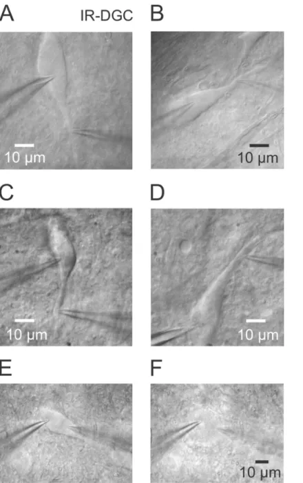
1. Within the substantia nigra select a healthy neuron with long dendrites that can be followed over a long distance in approximately the same plane (Figure 1A and 1B) using IR-Dodt Gradient Contrast (IR-DGC). Choose a smooth and homogeneous cell body. Avoid the two strongly contrasted cells at the surface of the slice (Figure 1C and 1D), because it is difficult to break in and to preserve stable recording conditions over time (stable series resistance). Select neurons that have their soma 10 - 30 µm underneath the slice surface. 2. Move the somatic electrode close to the soma (40 - 50 µm away) and the dendritic electrode close to the dendrite at the same distance.
Use a 2X magnification (fourfold changer) to select and patch a portion of a dendrite. Obtain on the monitor an absolute magnification of 2,100X without magnification (1X) and of 5,500X with a 2X magnification.
3. Slightly release the pressure of the somatic pipette by 10 mbar. If necessary, regulate dendritic and somatic pipette pressure to avoid displacement of the cell structure (soma and dendrite) within the slice.
4. Position the dendritic pipette close to the membrane in order to see a small dimpling. Release the pressure on the pipette tip and patch the dendrite while controlling the pipette resistance. In ideal conditions, only a very slight suction is sufficient to obtain a good seal. 5. Keep the dendritic pipette in the cell-attached mode. Move the somatic pipette close to the somatic membrane and patch the somatic
membrane. Ensure that a high seal resistance is obtained before rupturing the cell membrane (> 1 GΩ) 39. Slightly retract both pipettes away from the membrane by a couple of µm to avoid deformation of the cell body and dendrite.
6. For both pipettes, reduce as much as possible the amplitude of the pipette capacitance transients on top of the current step using a voltage pulse with high gain and little filtering 51 and the oscilloscope. Enter into the whole-cell mode with the dendritic pipette and subsequently with the somatic pipette.
7. Eliminate the whole-cell capacitance transients and compensate for series resistance. Monitor and document the access resistance at the beginning of, and regularly during, the experiment. If series resistance is too high (>50 MΩ), retry with another pipette.
8. Collect IR-DGC pictures (Figure 1A and 1B) with a video graphic printer 25, a frame grabber or a digital camera at high and low magnifications.
NOTE: Swelling of neurons during recording (Figure 1E and 1F) is sporadically observed, but rarely when the osmolarity and pH of solutions is correctly adjusted 39.
9. Obtain double somatic whole-cell recordings (soma - soma) with the same procedure (Figure 2A).
6. Apply long (several hundreds of ms) increasing depolarizing current steps sequentially with the somatic and dendritic pipette to evoke APs (Figures 2B, 3C and 3D). Record the resulting potential at the dendritic and somatic pipette simultaneously.
7. Examine the propagation of artificial excitatory postsynaptic potentials (aEPSPs) in dopaminergic neurons
1. Create an excitatory postsynaptic current (EPSC) waveform to inject as a current command during dual current-clamp recordings (Figures 4A and 4B). To do this, build a double exponential function with amplitude and time course values corresponding to real values measured for EPSCs in the neuron of interest 55. Carefully control the sampling rates of the constructed EPSC and of the injected EPSC waveform to preserve the original time course.
Note: Before applying the waveform in a real neuron, test it using a model cell.
2. Sequentially inject the waveform via the dendritic and somatic pipette and record resulting potentials for both somatic and dendritic pipettes concomitantly. Check regularly for possible drift of pipettes.
8. Terminating the recording from a neuron
1. Take an IR-DGC picture at a low magnification (objective: 5X or 10X) to document the position of the neuron within the slice and the electrodes.
2. Slowly and gently withdraw the dendritic and the somatic pipettes from the neuronal membrane sequentially in order to form outside-out patches with both pipettes. Remove the pipette using a sequence of lateral-upward movements 38. These should be short at first and then gradually increase in length. This recording configuration favors the proper closing of the cell membrane.
3. Monitor the decrease of capacitive currents (increase in the access resistance) in response to a 5 mV voltage pulse in voltage-clamp while withdrawing the pipette.
4. Once the membrane is sealed around the pipette tip, take it completely out of the recording chamber. Remove the objective from the bath. Keep the slice in the recording chamber for 15 - 20 min in standard ACSF to allow equilibration of biocytin (from the intracellular solution) in the recorded neuron.
5. Gently transfer the slice using the large opening of a Pasteur pipette into a 25 mL wide mouth amber (brown) glass bottle containing standard ACSF. Close the bottle with a cap. See paragraph 6 for the fixation step.
5. Cell-attached Recordings
1. Select a neuron with a dendrite extending over a long distance in the same plane. Ensure that the dendrite of interest can be followed to a well-defined soma.
2. Fill the patch pipette with electrode solution (Table 4). Design the solution to record the current of interest in the cell-attached configuration by including specific pharmacological agents to block other ion channels.
3. Patch the dendrite in the cell-attached mode
1. Visualize a portion of the dendrite and approach the recoding pipette using the manipulator. Adapt the pressure at the pipette tip by checking the manometer (70 - 80 mbar) to avoid displacement of the dendrite. Patch the dendrite as described in 4.5.4.
2. Record some IR-DGC pictures (Figure 5A). Try to obtain a seal resistance as large as possible (>1 GΩ 39), at best between 3 - 10 GΩ for cell-attached recordings 18 (Figure 5B). Retract the pipette away from the membrane by a couple of µm to avoid deformation of the dendrite.
3. Observe action currents in the cell-attached mode reflecting spontaneous action potentials of nigral neurons. Supplement the ACSF with Ca2+ and Na+ channel blockers (CdCl2 and TTX, respectively) to suppress action currents.
4. Apply a 2 s voltage step of -90 mV from a holding potential of 0 mV to the patch to evoke Ih (Figure 5C). Keep in mind that the pipette potential and the resting membrane potential are in series in the cell-attached configuration 56. For more details, see The Axon guide and Ref. 39.
5. Check regularly for possible drift of the pipette.
6. At the end of the recording, rupture the patch to go in the whole-cell mode and immediately take a readout of the membrane potential. Retract the pipette as described in sections 4.8.2 and 4.8.3 to obtain an outside-out patch.
4. Record from the corresponding soma in the whole-cell mode
1. Look along the dendrite and locate the corresponding soma. Use a high-resistance pipette (5 - 10 MΩ) 6,14,57 filled with a K+-based intracellular solution (Table 3). Apply a brief suction (negative pressure) to the pipette tip to rupture the membrane in order to enter in the whole-cell mode.
2. Check for the identity of the neuron in current-clamp by applying long hyper- and depolarizing current steps (Figure 5D) and allow biocytin to diffuse along dendrites. Apply short depolarizing current steps to visualize the AP time course.
3. After ≤10 min, withdraw the pipette to obtain an outside-out patch as described in sections 4.8.2 - 4.8.3. Gently transfer the slice using the large opening of a Pasteur pipette into a 25 mL amber glass bottle containing standard ACSF. Close the bottle with a cap. 4. Alternatively, first obtain a somatic whole-cell with a pipette solution containing additionally a fluorescent dye. Allow the diffusion of
the dye and select a portion of a dendrite 26. With a second pipette, patch the dendrite in the cell-attached mode. Use a confocal microscope if available to improve the visualization of the fluorescently labeled dendrite 14,22.
5. Perform dendritic recordings in the outside-out configuration, alternatively or additionally to the cell-attached recordings 10,22. See an example of a voltage-gated currents recorded from an outside-out patch in Figure 5E and 5F.
6. Biocytin Labeling of Nigral Neurons
1. Fixation of the tissue1. If possible, use separate rooms for slice recording/histochemical processing38.
2. Fix the slices by replacing the ACSF with 4% paraformaldehyde in 0.1 M phosphate buffer saline (PBS, pH = 7.4) with a Pasteur pipette. Always use freshly prepared fixative solution (<< 1 week old).
CAUTION: Use appropriate hand gloves and a chemical hood placed in a histology laboratory to manipulate paraformaldehyde because of its toxicity. Read the safety data sheet of this dangerous product before use and check the regulations concerning chemical safety (Dangerous Substances Directive (67/548/EEC) from the EU Commission) as this powder is thought to induce cancer. Other details are in Ref. 58.
3. Place the slices at 4 °C overnight. Avoid contamination of the patch-clamp setup or any equipment used for electrophysiology by paraformaldehyde.
4. After fixation, replace the fixative solution with PBS. Use a different Pasteur pipettes for removing the fixative solution and applying the PBS. Store slices in PBS at 4 °C before further processing (1 - 2 weeks). In this case, replace PBS twice a week. Use always freshly prepared PBS (<< 1 week old).
2. Staining of the tissue
1. Prepare a 24 well cell culture plate for the staining steps. Use clean equipment to transfer slices. Rinse the slices 3 x 5 min using fresh PBS.
2. Apply Fluorescein Avidin DCS (Avidin D, cell sorter grade; 1 µL fluorescein / mL Triton X-100) and 0.3% Triton X-100 in PBS at 4 °C overnight. Protect the slices from light throughout the staining. As an alternative to fluorescence, label neurons via 3,3'-diaminobenzidine for light or electron microscopic analysis 21,58.
CAUTION: Triton X-100 is dangerous. Read safety data sheet and EU Commission Directives before using this substance.
3. Rinse 3 x 30 min with PBS and subsequently with PB (phosphate buffer, to avoid the formation of crystals at the surface of the slice). 3. Mount the slices on standard glass slides. Cover the slices carefully with an embedding medium. Avoid air bubbles in the embedding
medium. Put the coverslip gently in order to cover completely the slice. Air-dry the slides overnight before visualizing them with a microscope. 4. Store the labeled slices at 4 °C after visualization. Useful tricks on histochemical procedures are in Refs. 58,59.
7. Post Hoc Visualization of Biocytin-filled Neurons
1. Use a confocal microscope to visualize the morphology of recovered neurons.1. Roughly locate the fluorescently labeled neuron in the slice with epifluorescence. Examine the dendritic arbor of neurons and locate the axon and axonal bleb (2 - 4 µm Ø) using a 10x or 20x objective. Document the course of the axon.
2. Switch to the confocal microscope and select the 488 nm laser diode to excite the fluorescein contained in the labeled neuron. Follow the extension of the axon and dendrites in the z-axis.
3. Record successive images in order to obtain a z-stack for the entire cell. Adjust the resolution of the z-axis (distance between consecutive images) to 0.5 - 1 µm. Collect confocal images of a cell using low (10X objective) and high (60X objective, oil-immersion) magnification.
4. Open the image file of the neuron obtained with the confocal microscope with an imaging software (ImageJ) 60. Compare the z-projection image with an IR-DGC image by eye to locate the precise position of the patch pipettes during the electrophysiological recording (Figures 1, 2A, 3A, 4A, 5A and 5E).
5. Determine morphometries of labeled neurons: measure the axon - soma distance, distances between recording pipettes along the somatodendritic domain and between the dendritic pipette and axon using the "Measure" function in ImageJ.
6. Reconstruct some neurons with NeuronJ (ImageJ), Imaris29 or Neuromantic 61.
8. Analysis of Electrophysiological Data
1. Use the software package associated with the amplifier to grossly analyze the data (e.g., Clampfit) or directly another software for data analysis such as Stimfit, an open source software 62,63 as in our recent publication 13 or for example WinWCP.
Representative Results
The above-described protocol intends to facilitate the collection of data using dendritic patch-clamp recordings. This technique, combined with
post hoc histochemistry, helps to gain insights into the mechanisms of many electrical signals originating or spreading into dendrites. Direct
access to dendrites with patch pipettes is difficult, but special attention to several methodological aspects will improve the success rate of the recordings. An experimenter sufficiently experienced in stable somatic recording can expect to obtain high resistance (GΩ) seals and complete experiments on most of attempts. One to two high-quality dendritic recordings can be collected per dissection.
The availability of high-quality brain slices containing healthy somata and dendrites is a prerequisite for accessing these fine structures (Figure 1). The criteria for selecting these neurons are a smooth and homogeneous surface all over the cell and a soma and dendrites with low contrast when observed with optimal adjusted optics (Figure 1A and 1B). Selecting neurons too strongly contrasted generally leads to unstable recordings (Figure 1C and 1C). Therefore such neurons should be avoided.
In comparison to other neurons, nigral DA neurons display specific morphological and electrophysiological characteristics. These features usually assessed with a single somatic pipette can also be observed in dual somatic (Figure 2) and somatodendritic recordings (Figure 3). Long hyperpolarizing current injections induce a membrane potential rectification called 'sag' (Figures 2B and 5D). The axon originates, in most cases, on a dendritic site as identified using complementary criteria 13,25,26, indicating that the dendritic compartment in these neurons is heterogeneous (Figure 3A - 3B). As a consequence, the compartment where the AP is observed first corresponds to the compartment in which the axon emerges (Figure 3C - 3D) 13,25,26. The axon is generally terminated by an axonal bleb caused by a cutting of the axon during slicing 64, but this structure is not systematically detected.
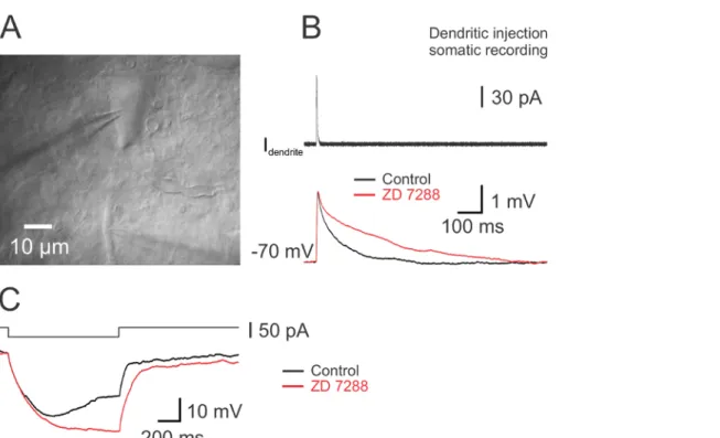
The pronounced sag observed in nigral DA neurons consecutive to the activation of Ih suggests a high expression of HCN subunits. To determine the influence of Ih on the integration of synaptic signals, synaptic-like current (EPSC) waveforms were generated and injected via the dendritic recording electrode during somatodendritic dual recordings 55 (Figure 4). The kinetics of these simulated EPSCs were based on the rise and decay time constants of real spontaneous EPSCs. The resulting aEPSP was recorded with the somatic electrode. Bath application of the
Ih blocker ZD 7288 increased the duration of the aEPSP, indicating the contribution of Ih to the time course of synaptic signals (Figure 4B). ZD 7288 abolished also the membrane potential rectification confirming that the sag results from the activation of Ih (Figure 4C). The results obtained with simulated EPSPs might be correlated to experiments using electrically evoked EPSPs 65. To map the precise distribution of the channel in the somatodendritic domain of DA neurons, cell-attached recordings were implemented (Figure 5). A high-resistance seal (>> 1 GΩ) is an absolute necessity for cell-attached recordings (Figure 5B). In dendrites of DA neurons, Ih activates slowly with long hyperpolarizing voltage steps and the current steady-state is attained after hundreds of ms (Figure 5C), as previously shown 66. This observation indicates that HCN channels expressed in dendrites of DA neurons have different subunits in comparison to those in pyramidal neurons or other cell types 10,16,66. As the distribution of the channel might be nonhomogeneous in the dendritic compartment and as the dendritic compartment is itself heterogeneous, the identity of the dendrite (axon-bearing or nonaxon-bearing dendrite) is revealed by comparing the IR-DGC image with the confocal image after biocytin staining (Figure 3A and B). Recovery of cell morphology is therefore necessary for both dual somatodendritic recordings and for cell-attached recordings via subsequent somatic whole-cell recordings.
Figure 1. Visualizing the Soma and Proximal Dendrites of Nigral Dopaminergic Neurons Using Infrared Videomicroscopy. (A) IR-DGC image of a nigral DA neuron showing the soma and proximal dendrite and both somatic and dendritic pipettes. A dual somatodendritic recording was successfully performed on this healthy neuron. Observe the low contrast and the smooth surface all over the somatodendritic domain of the cell. (B) Another example of a healthy DA neuron. (C) DA neuron with a rougher and uneven surface and a stronger contrast. While a dual recording has been obtained, the stability was suboptimal, and the recording duration was short (~ 15 min) due to a gradual increase of the access resistance at both pipettes. (D) Second example of a DA neuron showing a strongly contrasted soma and proximal dendrite. In this case, a strong increase of the access resistance was observed shortly after the break in the whole-cell mode. An attempt to decrease the access resistance by negative pressure was unsuccessful. Neurons in panel C and D might have been damaged during the slicing procedure and should be avoided for experiments. (E) Simultaneous double somatic recording in a healthy DA neuron at the beginning of the recording. (F) Same neuron as in panel E with a swollen cell body after ~17 min. Note the full absence of contrast, the ball-like appearance of the soma and the presence of the large nucleus which is not apparent in healthy neurons. Please click here to view a larger version of this figure.
Figure 2. Simultaneous Double Somatic Recording from a DA Neuron. (A) IR-DGC image during double somatic recording from a DA neuron. (B) Hyperpolarizing and depolarizing 1 s long current injections (-160 to 80 pA, increment 80 pA) and corresponding voltage changes recorded simultaneously with both patch pipettes. Note the presence of the sag in the voltage trace with the long hyperpolarizing current step and the large after-hyperpolarization after the AP during the depolarizing current pulse. Please click here to view a larger version of this figure.
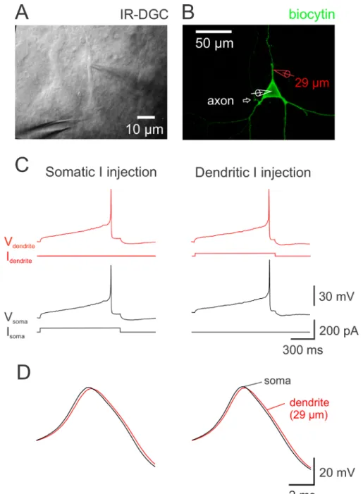
Figure 3. Dual S omatodendritic Recording in a DA Neuron. (A) IR-DGC image of a DA neuron. The distance between the dendritic and somatic pipette is 29 µm. (B) Confocal z-projection image of the neuron in panel A labeled with avidin conjugated to fluorescein isothiocyanate (FITC). The neuron was filled with biocytin during recording. The axon originated from a proximal dendrite close to the soma as indicated by the arrow. (C) Simultaneous dual somatodendritic whole-cell voltage recording from the neuron in panel A. AP recorded in the soma (black voltage traces) and dendrite (red voltage traces) in response to a 1 s long current injection step via the somatic (left; black current trace) and alternatively dendritic pipette (right; red current trace). (D) Somatic and dendritic AP shown at expanded time scale. With either somatic or dendritic current injection, the somatic AP (black) preceded the dendritic AP (red). The delay between APs in this neuron was 120 µs and 210 µs with somatic and dendritic current injection, respectively. Delays were measured at AP half-maximal amplitude during the rising phase of the AP. The AP is observed first in the compartment close to which the axon emerges, confirming previous observations 25,26. In this case, the dendritic recording is made from an axon-lacking dendrite. An example of a recording from an axon-bearing dendrite is in Ref. 13 (in their Fig. 1). Please click here to view a larger version of this figure.
Figure 4. Propagation of Artificial EPSPs Along the Somatodendritic Axis of DA Neurons. (A) IR-DGC image of a DA neuron. The distance between the dendritic and somatic pipette is 45 µm. Both patch pipettes are in the whole-cell current-clamp recording mode. (B) Current recorded with the dendritic pipette in current-clamp and used to generate the artificial EPSP (top). The current is obtained by the injection of an EPSC-like waveform (τrise = 0.6 ms; τdecay = 3 ms; amplitude = 100 pA) via the dendritic recording pipette 55. At the bottom, propagated aEPSPs recorded at the soma in control conditions (black) and after the bath application of the Ih blocker ZD7288 (30 µM; red trace). Each voltage trace is the average of 40 single sweeps. Observe the large increase in EPSP duration in the presence of ZD7288 indicating the contribution of Ih to the time course of EPSPs. (C) Voltage traces recorded from the soma in control conditions (black) and after the application of 30 µM ZD 7288 (red) in response to a long (30 pA; 1 s) hyperpolarizing current step. Note the absence of the membrane potential rectification (sag) after the blockage of Ih. Please click here to view a larger version of this figure.
Figure 5. Presence of Ih in Dendrites of DA Neuron. (A) IR-DGC image of a DA neuron and pipette on proximal dendrite. (B) Capacitive and leak currents during a 5 mV voltage command in cell-attached configuration. The seal resistance was 5 GΩ in this example. (C) Hyperpolarizing voltage step (90 mV; top) from a membrane potential of 0 mV induced a slowly activating Ih. The current trace was inverted and fitted with a single exponential function giving a time constant of τ = 632 ms. (D) Voltage responses of the whole-cell recorded soma (panel A) to 1 s hyper-and depolarizing current pulses (-160 to 120 pA, 40 pA increment). The somatic whole-cell recording was performed after the cell-attached recording. Note the absence of APs due to the extracellular application of TTX and Cd2+ to suppress spontaneous firing during cell-attached recording. These voltage-gated Na+ and Ca2+ current blockers were added to suppress action currents. Panels A - D are from the same neuron. (E) IR-DIC image of another DA neuron and a dendritic pipette. (F) Voltage-dependent currents activated by a test pulse to 0 mV from a 50 ms prepulse at -120 mV in an outside-out patch excised from the proximal dendrite of the neuron in panel E. Holding potential -80 mV. Note the time-dependent inactivation of the current. Please click here to view a larger version of this figure.
Substance g/mol Concentration for 1 L
NaCl 58.443 125 mM 7.305 g NaHCO3 84.007 25 mM 2.100 g KCl 74.551 2.5 mM 0.186 g NaH2PO4 137.99 1.25 mM 0.172 g glucose 198.17 25 mM 4.95 g MgCl2 1 M (solution) 1 mM 1 mL CaCl2 1 M (solution) 2 mM 2 mL
Osmolarity : ~ 310 mOsmol/L (optimal range: 314 – 325 mOsmol/L) , pH = 7.4 Table 1: Artificial cerebrospinal fluid (ACSF).
Substance g/mol Concentration for 1 L NaCl 58.443 87 mM 5.084 g NaHCO3 84.007 25 mM 2.1001 g KCl 7.551 2.5 mM 0.18637 g NaH2PO4 137.99 1.25 mM 0.17248 g MgCl2 1 M (solution) 7 mM 7 mL glucose 198.17 10 mM 1.9817 g sucrose 342.29 75 mM 25.672 g CaCl2 1 M (solution) 0.5 mM 0.5 mL Osmolarity : ~ 326 mOsmol/L, pH = 7.4 Table 2: Sucrose-ACSF to prepare slices.
Substance g/mol Concentration for 100 mL
KMeSO4 150.2 120 mM 1.8024 g KCl 74.56 20 mM 0.14912 g MgCl2 1 M (solution) 2 mM 200 µl Na2ATP 551.1 2 mM 0.1102 g Na2GTP 523.2 0.5 mM 0.02661 g Na2-Phosphocreatine 255.1 5 mM 0.1275 g EGTA 380.4 0.1 mM 3.803 mg Hepes 238.31 10 mM 0.23831 g Biocytin 1 mg/mL 0.1 g
Osmolarity : ~ 302 mOsmol/L , pH = 7.2 adjusted with KOH Table 3: Intracellular solution for dual recordings.
Substance g/mol Concentration for 100 mL
KCl 74.56 120 mM 0.8947 g CaCl2 1 M (solution) 2 mM 200 µl MgCl2 1 M (solution) 1 mM 100 µl Hepes 238.31 10 mM 0.23831 TEA-Cl 165.7 20 mM 0.3314 g 4-AP 94.11 5 mM 0.04705 g BaCl2 244.26 1 mM 0.02443 g CdCl2 183.32 0.02 mM 0.3666 mg TTX 1 mM 200 nM 20 µl
Osmolarity: ~ 290 mOsmol/L, adjusted with D-glucose (Ref. 16); pH = 7.4 Table 4: Electrode solution for cell-attached recordings.
Discussion
This report describes a step-by-step protocol to implement dual somatodendritic whole-cell recordings and local dendritic recordings. It is useful for determining the influence of ion channels (i.e., Ih) on the time course of postsynaptic potentials and mapping the distribution of the ion channel (Ih) along the somatodendritic domain of nigral DA neurons, respectively. Resulting electrophysiological measurements are combined to post hoc histochemistry to recover cell morphology. The procedure was employed to investigate DA neurons located in the substantia nigra, but can be generalized for neighboring nigral GABA neurons, ventral tegmental area DA neurons or other midbrain neurons. All the steps can also be followed to examine other ion channels expressed in dendrites of nigral neurons without important modifications. Post hoc visualization is particularly pertinent for neurons with axon-bearing dendrites, such as nigral neurons 25,26, hippocampal oriens-alveus interneurons 21 or some CA1 pyramidal neurons 67. Interestingly, neurons sharing this feature seem to be more common than generally thought 67. Morphological analysis
reveals also the precise position of the electrodes and axon. The detection of the latter may be optimized by the labeling of proteins expressed in the axon initial segment (voltage-gated Na+ channels or Ankyrin G) using immunohistochemistry 68,69.
The reliability of data collected with dendritic recordings and subsequent neuronal labeling invariably depends on the slice quality. Maximum effort needs therefore to be applied to preserve the viability of cells within the tissue. This is achieved with gentle handling of healthy animals, high-quality tools and reagents, sufficient oxygenation of the tissue and ice-cold temperatures throughout the preparation of slices. Stable recording conditions rely on the selection of healthy neurons. In the whole-cell mode, series resistance should initially be as low as possible and maintained constant throughout the experiment. The stability of the recordings is further dependent on high-quality manipulators devoid of drift and vibrations. These perturbations can be reduced by optimizing the pipette stability: checking the connection to pipette holder and to headstage, controlling that micromanipulator cables are slack, avoiding sudden changes in temperature or stage movement and checking the mechanism of the manipulator. For dual recordings, methylsulfate 13,15,21 has been included in the intracellular solution, but gluconate 9,14,25 can alternatively be employed. However, the main anion may alter the membrane potential 70,71 and some voltage-dependent currents 72. Intracellular solution may be supplemented with ATP, GTP and phosphocreatine to preserve the physiological functions of neurons. Additionally, adding a fluorescent dye in the pipette solution (e.g., Alexa 594 or Sulforhodamine 101 41) to visualize the dendrites during a somatic recording can be useful for instance to place a pressure application (Figure 7 in Ref. 41) or an electrical stimulating pipette. The pipette solution for cell-attached recordings contains a high K+ concentration and no Na+ to record large Ih. Noteworthy the Na+/K+ concentration ratio influences the current amplitude 10, the reversal potential of the current 11 and the gating of Ih 73. Alternatively, Ih can also be recorded using outside-outs 10. In this recording configuration however, the intracellular milieu in the proximity of the channels may be perturbed. Consequently, differences in the voltage-dependent activation of Ih is observed when comparing currents obtained using cell-attached patches and outside-outs 10. Swelling of neurons is occasionally encountered during patch-clamp recording, and often arises from distinct causes such as the low quality of the water, strong imbalance in osmolarity or pH between the intra- and the extracellular solutions 39 or errors in the composition of solutions. The quality of electrophysiological recordings has a direct incidence on the quality of the morphology of recovered neurons. High resistance somatic pipettes are used for dual recordings (6 - 10 MΩ, as in Refs. 6,11) and for single somatic recordings after cell-attached recordings to minimize the dilution of the intracellular milieu 14. The whole-cell somatic recording following the cell-attached recording is therefore kept short (< 10 min). Outside-out patches from both the somatic and dendritic pipettes are essential for proper closing of the cell membrane and subsequent recovery of the cell morphology. In addition to the cell's structure, the neurochemical content may be determined for the recorded neurons 59,74. For instance, the intracellular protein tyrosine hydroxylase can be immunolabeled for unequivocal identification of DA neurons 13.
DA neurons are mainly concentrated in the SN pars compacta, with a much lower density present in the SN pars reticulata, where they are intermixed with a higher number of GABA neurons 75. While the cell body of DA neurons is often larger than that of GABA neurons, the visual identification of these cells with IR-videomicroscopy is uncertain and partially hindered by the opacity of the pars compacta. To circumvent these limitations, the pre-selection of DA neurons can be facilitated by the use of transgenic mice expressing a fluorescent marker in a specific population of neurons (TH 65 or DAT for DA neurons, GAD for GABA neurons) and epifluorescence illumination. Alternatively, a fluorescent dye may be included in the solution of the somatic electrode to facilitate the visualization of dendrites. Increased resolution of the fluorescent cell is brought by Nipkow spinning disk confocal 14,22,30 or two-photon microscopy 7 combined to IR-DGC 6. Several advantages are related to DGC in comparison to DIC. First, as DIC prisms are not required, the IR-DGC image can be overlaid with a fluorescence image 49,52,53,76. Second, DGC can be combined with photostimulation and optogenetics 77.
A disadvantage of slice preparation is the preservation of the integrity of neurons. DA neurons extend their dendrites in the three spatial planes 78,79 and therefore truncation of the dendritic compartment cannot be completely avoided in slices 80. The choice of the orientation of slices (coronal, horizontal or parasagittal) is a trade-off. The origin of the innervation and the experimental design must be considered to select the right orientation of slices.
Direct dendritic patching is the technique used to map the distribution of functional ion channels in the different compartments of cells. In addition, this technique offers to determine the variability in functional properties of channels 20. As a complement the location and density of ion channels can be ascertained using immunohistochemistry at the light and electronic microscopy levels 17,23. This approach also offers the possibility to determine the channel density in small caliber structures which are inaccessible to patch pipettes. However these channels might be in a distinct functional state 24 or even inactive in comparison to those recorded using patch-clamp techniques. Both techniques are therefore necessary to obtain a complete picture of the location and properties of ion channels in a specific cellular region 17. With the development of voltage-sensitive dyes, voltage imaging has been used to examine the propagation of APs and EPSPs in neurons at multiple locations 81. As an alternative to dual patch-clamp recordings, this approach can even be implemented for thin dendrites that are not accessible to patch pipettes but necessitate accurate calibration of the signal and averaging.
While DA neurons in the SN and ventral tegmental area are widely investigated via somatic recordings in the physiological and
pathophysiological context, the functional properties of their dendrites remains largely unknown in both conditions. Patching from dendrites has been implemented for nigral dopamine neurons by several groups with success 13,25,26 and remains the method of choice to dissect excitable properties of these fine subcellular structures 8. Dendritic recordings provide a further opportunity to scrutinize the efficiency and plasticity of synaptic transmission and the plasticity of dendritic excitability 82,83.
Disclosures
The author declares that he has no competing financial interests.
Acknowledgements
manuscript. This work was supported by grants from the Belgian F.R.S. - FNRS (U.N002.13 and T.N0015.13) and published with the support of the Belgian University Foundation (Publié avec le concours de la Fondation Universitaire de Belgique).
References
1. London, M., & Häusser, M. Dendritic computation. Annu Rev Neurosci. 28, 503-532 (2005).
2. Stuart, G. J., & Spruston, N. Dendritic integration: 60 years of progress. Nat Neurosci. 18 (12), 1713-1721 (2015).
3. Sakmann, B., & Neher, E. Patch clamp techniques for studying ionic channels in excitable membranes. Annu Rev of Physiol. 46, 455-472 (1984).
4. Dodt, H. U., & Zieglgänsberger, W. Infrared videomicroscopy: a new look at neuronal structure and function. Trends Neurosci. 17 (11), 453-8 (1994).
5. Geiger, J., et al. Patch-clamp recording in brain slices with improved slicer technology. Pflug Arch. 443 (3), 491-501 (2002).
6. Nevian, T., Larkum, M. E., Polsky, A., & Schiller, J. Properties of basal dendrites of layer 5 pyramidal neurons: a direct patch-clamp recording study. Nat Neurosci. 10 (2), 206-214 (2007).
7. Delvendahl, I., Straub, I., & Hallermann, S. Dendritic patch-clamp recordings from cerebellar granule cells demonstrate electrotonic compactness. Front Cell Neurosci. 9, 93 (2015).
8. Stuart, G., & Spruston, N. Probing dendritic function with patch pipettes. Curr Opin Neurobiol. 5 (3), 389-394 (1995).
9. Stuart, G. J., & Sakmann, B. Active propagation of somatic action potentials into neocortical pyramidal cell dendrites. Nature. 367 (6458), 69-72 (1994).
10. Magee, J. C. Dendritic hyperpolarization-activated currents modify the integrative properties of hippocampal CA1 pyramidal neurons. J
Neurosci. 18 (19), 7613-7624 (1998).
11. Berger, T., Larkum, M. E., & Lüscher, H. R. High I(h) channel density in the distal apical dendrite of layer V pyramidal cells increases bidirectional attenuation of EPSPs. J Neurophysiol. 85 (2), 855-868 (2001).
12. Hoffman, D. a, Magee, J. C., Colbert, C. M., & Johnston, D. K+ channel regulation of signal propagation in dendrites of hippocampal pyramidal neurons. Nature. 387 (6636), 869-875 (1997).
13. Engel, D., & Seutin, V. High dendritic expression of Ih in the proximity of the axon origin controls the integrative properties of nigral dopamine neurons. J Physiol. 593 (22), 4905-4922 (2015).
14. Hu, H., Martina, M., & Jonas, P. Dendritic mechanisms underlying rapid synaptic activation of fast-spiking hippocampal interneurons. Science. 327 (5961), 52-58 (2010).
15. Bischofberger, J., & Jonas, P. Action potential propagation into the presynaptic dendrites of rat mitral cells. J Physiol. 504 (2), 359-365 (1997). 16. Angelo, K., London, M., Christensen, S. R., & Hausser, M. Local and global effects of I(h) distribution in dendrites of mammalian neurons. J
Neurosci. 27 (32), 8643-8653 (2007).
17. Stuart, G., Spruston, N., & Häusser, M. Dendrites. Oxford University Press: Oxford ; New York, (2008).
18. Williams, S. R., & Stuart, G. J. Site independence of EPSP time course is mediated by dendritic I(h) in neocortical pyramidal neurons. J
Neurophysiol. 83 (5), 3177-3182 (2000).
19. Williams, S. R., & Stuart, G. J. Action potential backpropagation and somato-dendritic distribution of ion channels in thalamocortical neurons.
J Neurosci. 20 (4), 1307-1317 (2000).
20. Gasparini, S., & Magee, J. C. Phosphorylation-dependent differences in the activation properties of distal and proximal dendritic Na+ channels in rat CA1 hippocampal neurons. J Physiol. 541 (Pt 3), 665-672 (2002).
21. Martina, M., Vida, I., & Jonas, P. Distal initiation and active propagation of action potentials in interneuron dendrites. Science. 287 (5451), 295-300 (2000).
22. Kim, S., Guzman, S. J., Hu, H., & Jonas, P. Active dendrites support efficient initiation of dendritic spikes in hippocampal CA3 pyramidal neurons. Nature Neurosci. 15 (4), 600-606 (2012).
23. Lorincz, A., Notomi, T., Tamas, G., Shigemoto, R., & Nusser, Z. Polarized and compartment-dependent distribution of HCN1 in pyramidal cell dendrites. Nat Neurosci. 5 (11), 1185-1193 (2002).
24. Nusser, Z. Differential subcellular distribution of ion channels and the diversity of neuronal function. Curr Opin Neurobiol. 22 (3), 366-371 (2012).
25. Häusser, M., Stuart, G., Racca, C., & Sakmann, B. Axonal initiation and active dendritic propagation of action potentials in substantia nigra neurons. Neuron. 15 (3), 637-647 (1995).
26. Gentet, L. J., & Williams, S. R. Dopamine gates action potential backpropagation in midbrain dopaminergic neurons. J Neurosci. 27 (8), 1892-1901 (2007).
27. Stuart, G., Spruston, N., Sakmann, B., & Häusser, M. Action potential initiation and backpropagation in neurons of the mammalian CNS.
Trends Neurosci. 20 (3), 125-131 (1997).
28. Roth, A., & Häusser, M. Compartmental models of rat cerebellar Purkinje cells based on simultaneous somatic and dendritic patch-clamp recordings. J Physiol. 535 (Pt 2), 445-72 (2001).
29. Schmidt-Hieber, C., Jonas, P., & Bischofberger, J. Subthreshold dendritic signal processing and coincidence detection in dentate gyrus granule cells. J Neurosci. 27 (31), 8430-8441 (2007).
30. Nörenberg, A., Hu, H., Vida, I., Bartos, M., & Jonas, P. Distinct nonuniform cable properties optimize rapid and efficient activation of fast-spiking GABAergic interneurons. Proc Natl Acad Sci U S A. 107 (2), 894-9 (2010).
31. Pouille, F., & Scanziani, M. Enforcement of temporal fidelity in pyramidal cells by somatic feed-forward inhibition. Science. 293 (5532), 1159-1163 (2001).
32. Hornykiewicz, O. The discovery of dopamine deficiency in the parkinsonian brain. J Neural Transm. (70), 9-15 (2006).
33. Tepper, J. M., Sawyer, S. F., & Groves, P. M. Electrophysiologically identified nigral dopaminergic neurons intracellularly labeled with HRP: light-microscopic analysis. J Neurosci. 7 (9), 2794-806 (1987).
34. Cajal, S. R. Histologie du Système Nerveux de l'Homme et des Vertébrés. Tome premier.'Maloine Editeur. Paris Azoulay, L: Paris, (1909). 35. Cheramy, A., Leviel, V., & Glowinski, J. Dendritic release of dopamine in the substantia nigra. Nature. 289 (0028-0836 (Print)), 537-542
(1981).
37. Harnett, M. T., Bernier, B. E., Ahn, K.-C., & Morikawa, H. Burst-timing-dependent plasticity of NMDA receptor-mediated transmission in midbrain dopamine neurons. Neuron. 62 (6), 826-38 (2009).
38. Bischofberger, J., Engel, D., Li, L., Geiger, J. R., & Jonas, P. Patch-clamp recording from mossy fiber terminals in hippocampal slices. Nat
Protoc. 1 (4), 2075-2081 (2006).
39. Sakmann, B., & Neher, E. Single-channel recording. Springer US: New York, (1995).
40. Davie, J. T., Kole, M. H. P., et al. Dendritic patch-clamp recording. Nat Protoc. 1 (3), 1235-1247 (2006).
41. Weng, J.-Y., Lin, Y.-C., & Lien, C.-C. Cell type-specific expression of acid-sensing ion channels in hippocampal interneurons. J Neurosci. 30 (19), 6548-6558 (2010).
42. Kole, M. H., Hallermann, S., & Stuart, G. J. Single Ih channels in pyramidal neuron dendrites: properties, distribution, and impact on action potential output. J Neurosci. 26 (6), 1677-1687 (2006).
43. Angelo, K., & Margrie, T. W. Population diversity and function of hyperpolarization-activated current in olfactory bulb mitral cells. Sci Rep. 1, 50 (2011).
44. Brown, A. L., Johnson, B. E., & Goodman, M. B. Making patch-pipettes and sharp electrodes with a programmable puller. J Vis Exp. (20), 1-2 (2008).
45. Gibb, A. J., & Edwards, F. a Patch clamp recording from cells in sliced tissues. Microelectrode techniques, The Plymouth workshop
handbook. 255-274 (1994).
46. Edwards, F. A., & Konnerth, A. Patch-clamping cells in sliced tissue preparations. Method Enzymol. 207 (1980), 208-222 (1992).
47. Stuart, G. J., Dodt, H. U., & Sakmann, B. Patch-clamp recordings from the soma and dendrites of neurons in brain slices using infrared video microscopy. Pflug Arch Eur J Phy. 423 (5-6), 511-518 (1993).
48. Castañeda-Castellanos, D. R., Flint, A. C., & Kriegstein, A. R. Blind patch clamp recordings in embryonic and adult mammalian brain slices.
Nat Protoc. 1 (2), 532-542 (2006).
49. Dodt, H.-U., Becker, K., & Zieglgänsberger, W. Infrared video microscopy for visualizing neurons and neuronal excitation in brain slices. Cold
Spring Harb Protoc. 2013 (12), 1149-52 (2013).
50. Dodt, H. U., & Zieglgansberger, W. Visualizing unstained neurons in living brain slices by infrared DIC-videomicroscopy. Brain Res. 537 (1-2), 333-336 (1990).
51. Stuart, G. Patch-pipet recording in brain slices. Curr Protoc Neurosci. Chapter 6, Unit 6.7 (2001).
52. Dodt, H. U., Frick, A., Kampe, K., & Zieglgänsberger, W. NMDA and AMPA receptors on neocortical neurons are differentially distributed. Eur
J Neurosci. 10 (11), 3351-7 (1998).
53. Dodt, H.-U., Eder, M., Schierloh, A., & Zieglgänsberger, W. Infrared-guided laser stimulation of neurons in brain slices. Sci STKE. 2002 (120), pl2 (2002).
54. Warner Istruments, C. Techniques for Chloriding Silver Wires. (1999).
55. Stuart, G., & Sakmann, B. Amplification of EPSPs by axosomatic sodium channels in neocortical pyramidal neurons. Neuron. 15 (5), 1065-1076 (1995).
56. van Welie, I., van Hooft, J. a & Wadman, W. J. Homeostatic scaling of neuronal excitability by synaptic modulation of somatic hyperpolarization-activated Ih channels. Proc Natl Acad Sci U S A. 101 (14), 5123-5128 (2004).
57. Berger, T., Larkum, M. E., & Luscher, H. R. High I(h) channel density in the distal apical dendrite of layer V pyramidal cells increases bidirectional attenuation of EPSPs. J Neurophysiol. 85 (2), 855-868 (2001).
58. Marx, M., Günter, R. H., Hucko, W., Radnikow, G., & Feldmeyer, D. Improved biocytin labeling and neuronal 3D reconstruction. Nat Protoc. 7 (2), 394-407 (2012).
59. Booker, S. a., Song, J., & Vida, I. Whole-cell Patch-clamp Recordings from Morphologically- and Neurochemically-identified Hippocampal Interneurons. J Vis Exp. (91), 1-11 (2014).
60. Schindelin, J., Arganda-Carreras, I., et al. Fiji: an open-source platform for biological-image analysis. Nat Methods. 9 (7), 676-682 (2012). 61. Myatt, D. R., Hadlington, T., Ascoli, G., & Nasuto, S. Neuromantic - from semi manual to semi automatic reconstruction of neuron morphology.
Front Neuroinform. 6, 4 (2012).
62. Guzman, S. J., Schlögl, A., & Schmidt-Hieber, C. Stimfit: quantifying electrophysiological data with Python. Front Neuroinform. 8 (February), 1-10 (2014).
63. Schlögl, A., Jonas, P., Schmidt-Hieber, C., & Guzman, S. J. Stimfit: A Fast Visualization and Analysis Environment for Cellular Neurophysiology. BME / Biomed Tech (Berl). 58, 24-25 (2013).
64. Shu, Y., Hasenstaub, A., Duque, A., Yu, Y., & McCormick, D. A. Modulation of intracortical synaptic potentials by presynaptic somatic membrane potential. Nature. 441 (7094), 761-765 (2006).
65. Masi, A., et al. Differential contribution of Ih to the integration of excitatory synaptic inputs in substantia nigra pars compacta and ventral tegmental area dopaminergic neurons. Eur J Neurosci. 42 (9), 2699-2706 (2015).
66. Franz, O., Liss, B., Neu, A., & Roeper, J. Single-cell mRNA expression of HCN1 correlates with a fast gating phenotype of hyperpolarization-activated cyclic nucleotide-gated ion channels (Ih) in central neurons. Eur J Neurosci. 12 (8), 2685-2693 (2000).
67. Thome, C., et al. Axon-carrying dendrites convey privileged synaptic input in hippocampal neurons. Neuron. 83 (6), 1418-1430 (2014). 68. Kuba, H., Ishii, T. M., & Ohmori, H. Axonal site of spike initiation enhances auditory coincidence detection. Nature. 444 (7122), 1069-1072
(2006).
69. Dugladze, T., Schmitz, D., Whittington, M. a., Vida, I., & Gloveli, T. Segregation of Axonal and Somatic Activity During Fast Network Oscillations. Science. 336 (6087), 1458-1461 (2012).
70. Zhang, L., et al. Whole-cell recording of the Ca(2+)-dependent slow afterhyperpolarization in hippocampal neurones: effects of internally applied anions. Pflug Arch Eur J Phy. 426 (3-4), 247-53 (1994).
71. Kaczorowski, C. C., Disterhoft, J., & Spruston, N. Stability and plasticity of intrinsic membrane properties in hippocampal CA1 pyramidal neurons: effects of internal anions. J Physiol. 578 (Pt 3), 799-818 (2007).
72. Velumian, a a, Zhang, L., Pennefather, P., & Carlen, P. L. Reversible inhibition of IK, IAHP, Ih and ICa currents by internally applied gluconate in rat hippocampal pyramidal neurones. Pflug Arch Eur J Phy. 433 (3), 343-50 (1997).
73. Azene, E. M., Xue, T., & Li, R. a Molecular basis of the effect of potassium on heterologously expressed pacemaker (HCN) channels. J
75. Nair-Roberts, R. G., Chatelain-Badie, S. D., Benson, E., White-Cooper, H., Bolam, J. P., & Ungless, M. A. Stereological estimates of dopaminergic, GABAergic and glutamatergic neurons in the ventral tegmental area, substantia nigra and retrorubral field in the rat.
Neuroscience. 152 (4), 1024-1031 (2008).
76. Yasuda, R., et al. Imaging calcium concentration dynamics in small neuronal compartments. Sci STKE. 2004 (219), pl5 (2004).
77. Hsu, T.-T., Lee, C.-T., Tai, M.-H., & Lien, C.-C. Differential Recruitment of Dentate Gyrus Interneuron Types by Commissural Versus Perforant Pathways. Cereb cortex. , 1-13 (2015).
78. Lin, J. Y., van Wyk, M., Bowala, T. K., Teo, M.-Y., & Lipski, J. Dendritic projections and dye-coupling in dopaminergic neurons of the substantia nigra examined in horizontal brain slices from young rats. J Neurophysiol. 90 (4), 2531-2535 (2003).
79. Henny, P., et al. Structural correlates of heterogeneous in vivo activity of midbrain dopaminergic neurons. Nat Neurosci. 15 (4), 613-619 (2012).
80. van Pelt, J., van Ooyen, A., & Uylings, H. B. M. Axonal and dendritic density field estimation from incomplete single-slice neuronal reconstructions. Front Neuroanat. 8 (June), 54 (2014).
81. Popovic, M., et al. Imaging submillisecond membrane potential changes from individual regions of single axons, dendrites and spines. Adv
Exp Med Biol. 859, 57-101 (2015).
82. Sjostrom, P. J., Rancz, E. a, Roth, A., & Häusser, M. Dendritic Excitability and Synaptic Plasticity. Physiol Rev. 88 (2), 769-840 (2008). 83. Magee, J. C., & Johnston, D. Plasticity of dendritic function. Curr Opin Neurobiol. 15 (3), 334-342 (2005).