HAL Id: hal-01813601
https://hal.archives-ouvertes.fr/hal-01813601
Submitted on 12 Jun 2018
HAL is a multi-disciplinary open access
archive for the deposit and dissemination of
sci-entific research documents, whether they are
pub-lished or not. The documents may come from
teaching and research institutions in France or
abroad, or from public or private research centers.
L’archive ouverte pluridisciplinaire HAL, est
destinée au dépôt et à la diffusion de documents
scientifiques de niveau recherche, publiés ou non,
émanant des établissements d’enseignement et de
recherche français ou étrangers, des laboratoires
publics ou privés.
Compliance matrix model based on ship owners’
operational needs
Alan Guégan, Benoît Rafine, Laurent Descombes, Hanane Fadiaw, Pierre
Marty, Philippe Corrignan, Romain Le Nena
To cite this version:
Alan Guégan, Benoît Rafine, Laurent Descombes, Hanane Fadiaw, Pierre Marty, et al.. Compliance
matrix model based on ship owners’ operational needs. 7th Transport Research Arena TRA 2018,
Apr 2018, Vienne, Austria. �hal-01813601�
Proceedings of 7th Transport Research Arena TRA 2018, April 16-19, 2018, Vienna, Austria
Compliance matrix model based on ship owners’ operational
needs
Alan Guegan* a, Benoît Rafine b, Laurent Descombes c, Hanane Fadiaw c, Pierre
Marty d, Philippe Corrignan d, Romain le Nena b,
a Sirehna, 5 rue de l'Halbrane, 44340 Bouguenais, France b Naval Group, 40-42, rue du Docteur Finlay - 75732 Paris c IRT Systemx, 8, Avenue de la Vauve - 91127 PALAISEAU
d Bureau Veritas Marine & Offshore, 8, boulevard Albert Einstein, 44323 Nantes – France
Abstract
Automation, embedded software, stringent regulation and customer expectations have increased the complexity of ship design and requirements management. The requirements management approach described here brings two innovations with respect to existing tools used in the shipbuilding industry. First, requirements are assigned to operational scenarios rather than physical components to emphasize the focus on customer needs rather than subsystem optimization. Second, a tool based on a microservices architecture is introduced to manage scenario-centered “communities of interest” to which system architecture blocks and requirements subscribe depending on their involvement in the scenario. System architecture, operational scenarios, customer requirements are designed and managed in separate tools and the overall consistency of the design – reflected in the compliance matrix model - is preserved within each “community” they belong to. Collaborative ship design where partners provide diverse contributions to the design of a single vessel could benefit from such an approach.
Keywords: compliance matrix; requirements management; operational scenario; system architecture;
micro-services
* Corresponding author. Tel.: +33 2 44 76 34 49 ; fax: +33 2 44 76 57 01.
1. Introduction
Shipbuilding industry products are typically associated with large investments corresponding to one or several specific operational needs. Thus the maritime mode of transport does not benefit from the economy of series production and design studies are made on purpose for each ship. In this context, shipyards and designers shall be able to deliver, in a limited time, a ship design driven by a global trade off among operational requirements and constraints (rules, life-cycle cost, environmental impact…).
In addition, naval architects are facing increasingly complex ship designs and operations. This new challenge is induced by:
New technical missions often assigned to one single multi-purpose ship in order to reduce costs Increased interactions between external and internal assets of various types and sizes (onshore
communication centres, surrounding ships and aircrafts, UAV, USV, UUV, satellites, etc).
Integration of complex sub-systems with a high technology level and high connectivity or modularity.
Novel design methodologies have been introduced, some of which are reviewed in Andrews & Erikstad (2015). The HOLISHIP project addresses these challenges by developing systems engineering methods associated with numerical modelling and simulation tools. The final output of the project will be a software platform that enables naval architects to manage system complexity and reach a balanced design that takes into account all life cycle requirements (technical and cost).
This paper focuses on the System Architecture and Requirement management tool, the goal of which is to provide a general structure for managing system design and ensuring that customer requirements are satisfied. Requirements that are transverse to several subsystems and technologies are the main point of focus and should benefit the most from the tool being described here, as compared with local, subsystem-specific requirements. First, the design method is described. Whereas in textbook approaches requirements are assigned to physical equipment, here requirements are assigned to operational scenarios. Guidelines are provided on how to describe scenarios in an efficient way, and a method to describe system architecture in a comprehensive way is
introduced. Then, the procedure to link requirements with scenarios and eventually physical equipment within the architecture is described. This procedure consists of building “communities of interest” made of design artifacts of heterogeneous nature, such as architectural blocks, operational scenarios and requirements. Once the method has been described from a theoretical point of view, the practical nature of ship design is discussed and a software tool is described. By essence, ship design is iterative and involves multiple technical domains. The data flow during the design is heterogeneous – structural design, electrical design, hydrodynamics, etc. are all addressed simultaneously - and asynchronous since design decisions in a domain have impacts on any other technical domain that are difficult to anticipate. Software architectures have emerged in the past few years that excel at managing heterogeneity and asynchronicity. The approach described here acknowledges these two aspects of ship design and builds on state-of-the-art software architectures to address them. After a brief introduction to service-oriented and “microservices” architectures, their application to the development of a requirements management software is described. Eventually, the application of the tool to a test case is discussed, with a focus on compliance assessment.
2. Ship design driven by operational scenarios
2.1. Customer needs and operational scenarios
The design of a ship is driven by the future operational needs of the ship owner and by ship design regulations. The customer specification translates operational needs into technical requirements, e.g. “maximum ship speed shall be at least 20kts”, or “ship stability shall be preserved if 3 consecutive compartments are flooded”.
The common practice in naval architecture is to allocate these requirements to the various subsystems aboard the ship, complementing them with know-how and technical constraints such as manufacturing limitations of the shipyard. The compliance of the design to the requirements is evaluated and eventually demonstrated to the customer by means of technical analyses, numerical simulations, controls and tests.
Practically, acceptance tests for operational requirements are achieved by running scenarios that mimick actual operational situations with the vessel. In a sense, operational scenarios are at the beginning and at the end of the design and manufacturing process. In the course of the design, operational scenarios are broken down into a list of supposedly independent operational requirements that can be managed by independent design teams (engine, structure, hydrodynamics, fluids, and so forth).
When it comes to designing or refitting multi-purpose, energy-efficient, cyberproof ships, the requirements are strongly interdependent and the “breakdown” approach finds a limit. Heterogeneous yet interdependent requirements have to be managed together, as a whole rather than as a list of separate items. The common denominator of each group of requirements is the operational scenario to which they contribute.
The method described in this paper uses operational scenarios rather than technical requirements as the main drivers for the design. In the best case, operational scenarios are written together by the future ship owner and naval architects, otherwise the design teams reconstruct the scenarios from the requirements they have in the specification. This method has consequences for the tools and the governance of the design, that leave room to iterations and bottom-up contributions.
Operational scenarios are defined in IEC (2011) as “Description of an imagined sequence of events that includes
the interaction of the product or service with its environment and users, as well as interaction among its product or service components.” More specifically, the following rules for writing scenarios have been applied in
this paper:
• a scenario shall describe a single sequence of events – options, alternative or “branched” scenarios are prohibited,
• a scenario is a description and shall be written in the present tense – the use of “shall” or the conditional tense are prohibited,
• prerequisites and initial state are clearly identified (e.g. ship configuration, environmental conditions), • final state is clearly identified as well (e.g. ship sails at cruise speed),
• events are described in a chronological order with all relevant stakeholders, environmental conditions, operating modes of the ship and its subparts, etc.,
• measurable values are given whenever needed,
• the description has enough details so that the scenario can be “replayed” (with the actual vessel or by simulation).
2.2. Ship design :Product design and Functional design
A ship may be seen both as a product, in the sense that it is an assembly of components and physical artifacts of all kinds, and as a system that delivers services and performs functions. The challenge with complex ships – and complex systems – is to understand and manage the behaviour of the many components of the system as they work together, otherwise called emerging behaviours.
At the intersection between the “component” view and the “functional” one are the multiple interfaces between the components of the ship. It is because components have been connected (physically) that they can interact and generate emerging behaviours. In the most recent ships, for instance, the machinery (engine, energy production), the payload (cranes, ROV or helicopter facilities), the navigation instruments (radar, gps) and communication systems (VHF, AIS), the onboard networks, etc. are all interconnected.
In the following, the functional interfaces between the subsystems of the ship are mapped with system architecture diagrams (see Guegan et al (2017)). The top-level diagram of a multi-purpose surveillance vessel is given in Figure 1. The subsystems (or “blocks”) are displayed as ellipses and their physical interfaces (their “links”) are represented by solid lines. A line connecting a lower-level subsystem, e.g. “Ship Management System” (SMS), with the higher-level system it belongs to, e.g. “Ship”, is a shortcut for “SMS is ubiquitous and connected with many components within Ship”. Each “block” may be expanded to reveal its subcomponents (sub-blocks): the hierarchy of blocks provides a Product Breakdown Structure (PBS) of the ship system.
Fig. 1 (a) Top-level architecture diagram of a Multi-Purpose Surveillance Vessel; (b) detail of the Ship Management System.
2.3. Linking customer needs and ship design
The ship owner and the design team have shared interests in delivering a ship that best fits the operational needs. As stated in paragraph 2.1, the operational needs are expressed in terms of technical requirements in the customer specification. The actual life of the ship in operation is described in operational scenarios. The system architecture of the ship is described with system architecture diagrams (paragraph 2.2).
In current design approaches technical requirements are allocated to individual blocks within the PBS. This is perfectly fine for a number of “local” requirements specific to some subsystems such as for instance safety communication devices on the bridge. However, when requirements that involve several blocks are refined into requirements specific to a single block each, the transverse nature of these requirements is lost in the process, making it difficult to address emerging behaviours and strongly coupled interactions.
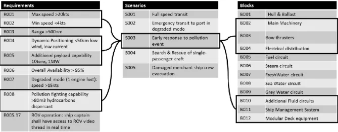
By contrast, in the approach described here requirements are allocated to the relevant operational scenarios, and then the list of all the blocks that contribute to any given scenario is drawn (Figure 2). The requirements and blocks that are linked to a given scenario may be seen as a “community of interest” whose members are interdependent. The main advantage of this approach is that transverse requirements or emerging behaviours are addressed globally within the scope of each operational scenario, rather than locally at the level of each component independently from its neighbours. In Figure 2, Max/Min speed, Dynamic Positioning accuracy, payload capability, etc. are addressed simultaneously to find a global trade-off in the design of the machinery, bow thrusters, ship management system, etc..
Fig. 2 The technical requirements (left) and the blocks composing the ship (right) are linked to the scenarios for which they are relevant (center). Together these elements constitute a “community of interest” around scenario S003 “Early response to pollution event”.
Adjustments to current engineering practices may be needed to take full advantage of the concept of “community of interest”. In this approach engineers are invited to participate in a design debate, to build a consensus around a technical solution that satisfies operational needs, rather than designing their own subsystem according to a
predefined list of requirements with little consideration for the overall optimum – arguably guaranteed by the a priori requirement refinement and allocation process.
Paragraph 3 builds on the most recent progress in software architecture to propose a software tool that supports the “community of interest” approach, in the view of filling up a comprehensive compliance matrix.
3. Ship design managed by “communities of interest”
3.1. Ship design: heterogeneity, asynchronicity, iterations
As for most industrial systems, a ship is composed of multiple subsystems that implement various technologies. The goal of the design process is to reach a balanced design in which all the technologies onboard work together smoothly while satisfying criteria such as, e.g. general arrangement consistency, ship stability, fire safety, Electro Magnetic Compatibility,...
The main challenge in the design process is to coordinate inputs from a large number of specialists, regarding several heterogeneous technical domains. Since subsystems share a lot of interactions, the design process is
iterative by nature: the behaviour of every subsystem in its environment cannot be defined a priori, and the design
proceeds by consecutive adjustments. In the general case, design processes have well-defined, synchronized milestones that take into account their iterative nature. Still, technical inputs are generated on a daily basis, following the work of the many engineers involved; the flow of technical information produced during the design process is asynchronous by essence. The goal of the HOLISHIP project is to develop methods and tools to address these issues with improved efficiency.
Managing heterogeneous, asynchronous inputs within iterative processes has been a big concern of the software community in the past few years. Some software architectures are particularly well suited for this purpose, among which the so-called “Microservices” approach used, e.g. by Netflix® (see Newman (2017)). The prime goal of Microservices is to parallelize software development by ensuring that the services and their several instantiations can be deployed independently. The principle is that context-bounded software “services” cooperate in a distributed framework that ensures a consistent output from the asynchronous contributions of all. Heterogeneity in the types of services provided is encouraged to provide the richest possible service to the end-user.
It might seem puzzling that software principles invoking independently deployable services might be of interest to solve the issue of transverse performances of ships. The reader is advised that, although Microservices supporters emphasize the independence of its components, the overall consistency of the services provided by the software to the end-user is never lost from sight. End-user (global) experience is a key driver of the design. It is monitored and managed in a variety of ways depending on companies, but it is the ubiquitous reference to assess the developments implemented within each individual service. Microservices software architectures are indeed very close to system architectures: in both cases the development of each component is assigned to specialized teams (electricity, machinery, etc. for a ship vs video streaming, community management, etc. for a web application software for instance), while the overall consistency of the service provided (ship speed and range vs video quality and response time, for instance) is guaranteed by the constant focus on the customer needs (operational scenarios, vs user experience “epics”).
The following sections describe how Microservices technologies can be used to implement a software tool for ship design. The tool is designed as a platform that allows “communities of interest” (see 0) to emerge and develop around each of the future ship owner’s operational needs; heterogeneity, asynchronicity and iterations are managed within each community of interest with the help of microservices technologies which principles are described in the following section.
3.2. A Micro-services-based software tool for ship design
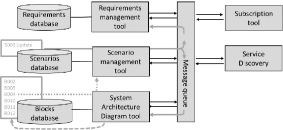
The architecture of the design management tool is sketched in Figure 3.
Requirements, Operational scenarios and Blocks from the system architecture diagram are managed with three separate tools (rectangles) that come with their own independent databases (cylinders). Each tool with its database is an independent context-bounded service.
Communication between services is performed in two different ways. Services can either exchange data by a standard request / response process, or share notifications with a publish / subscribe process (arrows). For the latter, the common practice is to implement a Message Queue (MQ) service. Each service is free to subscribe to notifications from other services; the role of the MQ is to dispatch the notifications from one service to the others, according to the subscription list.
When the amount of data is small enough, the notification sent through the MQ can embed all the information about the event (e.g., when a scenario is updated, the text of the scenario can be sent along with the notification). When the event involves larger amounts of data (e.g. when a whole set of scenarios has been imported from a previous project), the event is notified through the MQ but the services that need it exchange data outside the MQ, with a request / response process. This implies that the services that communicate know the addresses of one another. It is the role of the Service Discovery to return a list of all available services and their addresses upon request. This service is vital to the Microservices architecture since the list of available services is in constant evolution, whether new services are created, others are shut down, or overloaded, or moved to a new server, etc. The features above define an event-driven, service-oriented software architecture. Since the services involved are loosely coupled and limited in their scope (essentially, the management of one list of items each), it is fair to call it a Microservices architecture.
Before analyzing the way this architecture works, it is worth introducing the Subscription tool service. Communities of interest are created when the design team makes relevant associations between blocks, scenarios and requirements. The subscription tool enables the designers to select one item, say block B003, get the list of scenarios or requirements it has subscribed to, and update this list. To do so, the subscription tool uses the service discovery to know which items are managed by the services that are currently running; then, the subscription tool calls each of these services separately to know which items can be subscribed to, which subscriptions have already been registered, and to request updates when necessary.
Fig. 3 Architecture of the design management tool. Independent, context-bounded design and evaluation tools (left half of the sketch) are connected with a Microservices-inspired infrastructure (right: Message Queue, Subscription Tool, Service Discovery). An example data flow is displayed in grey lines.
An example might be useful at this point. Data transfer is illustrated with grey lines in Figure 3. Let us assume that, for some reason, scenario S003 has been updated by the design team. The update results in a change in the database of the scenario management tool; a notification is sent to the MQ (double-headed arrow) that S003 has been updted. The MQ propagates the notification to the services that had subscribed to “scenario update”
notifications, namely the architecture diagram and the requirements management tools (solid grey lines). Other, non-subscriber tools like Service Discovery are not informed.
Upon receipt of the notification the architecture diagram tool sends an alert to blocks B002,03,04,10,11,12 that had previously subscribed to “scenario S003 update” notifications. These blocks are highlighted in the diagram as displayed in the graphic interface of the System Architecture Diagram tool, which allows the designer of block B004 to 1/ acknowledge that S003 has been changed (notification process, dashed line) and 2/ if there is more information about the event than the one provided by the notification, send a request for additional information to the scenario management tool (request / response process, dotted line).
This basic architecture offers enough features to test the scenario-driven design method described in section 2. Yet it is worth to mention that it has a strong potential for evolutivity, like the implementation of other services dedicated to different aspects of ship design. It has already been planned to connect this tool and the simulation platform developed in the HOLISHIP project, in order to enable traceability between system architecture, requirements, scenarios, and ship performance simulations.
Section 3.3 provides an example of how this tool can be used to guide the design of a multi-purpose surveillance vessel. The design tool is tested on a pollution-fighting scenario relevant to this kind of ships. An additional focus is given on compliance assessment and the construction of a compliance matrix that matches the customer expectations while extending the scenario-oriented approach.
3.3. Compliance assessment with the compliance matrix : use case
In the upcoming example, the future owner of the ship requests a pollution fighting capability. The requirements listed in Figure 2 are an excerpt from the customer specification.
The following scenario (Figure 4), inspired both by experience acquired during the design of previous ships and by the specification from the customer, describes a meaningful operational context to analyse the requirements.
Fig. 4 - Operational scenario “Early Response to pollution event”. Requirements from the customer specification are underlined. The description of the scenario includes more information than the original specification. The goal is to remove any ambiguity from the specification and to provide a complete description of ship operation that can be shared with the customer to improve common understanding.
In most cases, the designer has a portfolio of several other ships with similar operating profiles. This is a source of inspiration for writing the scenario and also for initializing the design. Starting from a similar, existing design (the reference design), the designer draws the ship system architecture diagram displayed in Figure 1a.
The designer knows from the reference design that the following blocks are involved in scenario S003 : B002,03,04,10,11,12. Together with requirements R001,2,4,5,8 and scenario S003, they form a “community of interest” (Figure 2) regarding the pollution fighting capability of the vessel.
Video management is one example of a deviation from the reference design. The customer described in more detail what he expects during ROV operation, with the requirement R005.17 (Figure 2) that had never been encountered previously by the design team.
In the design management tool, requirement R005.17 is pointed out as an “orphan requirement” that has not subscribed to any scenario. The design team decides to: 1/ amend scenario S003 to incorporate R005.17 (the final version of the scenario is given in Figure 4, with R005.17 in bold font), 2/ subscribe R005.17 to S003 : R005.17 is now traced to S003 and enters the compliance demonstration workflow.
Compliance demonstration starts at system architecture level. All the blocks that have subscribed to S003 receive a notification that a new requirement called R005.17 has subscribed to S003, and that S003 has been updated. The subscribing blocks, including B012 Modular Deck Equipment, send a request to S003 to evaluate the impact the update might have. B012 is the source of the video thread from the ROV, and it has a high chance of being impacted. Thanks to the notification the designer is aware that the role of B012 with respect to requirement R005.17 needs to be investigated.
The architecture diagram in Figure 1b shows that there is no connexion between the bridge and block B012
Modular Deck Equipment: the modular ROV system is unable to communicate with the bridge. The designer finds
a way to satisfy requirement R005.17 by connecting B012 with the onboard network and implementing changes in the bridge and onboard network in terms of software and hardware. The designer updates the architecture diagram accordingly, as shown in Figure 5.
Fig. 5 – Updated architecture diagram of the Ship Management System. The update from Figure 1b consists in connecting the modular ROV equipment with the onboard network (dashed lines). ROV video is delivered to the crew at the bridge through the ship’s own network (arrow).
In a similar fashion as for the update in scenario S003, changes in the “onboard network” block and the “bridge” block are notified to the neighbouring blocks in the diagram, and to all the scenarios these blocks have subscribed to through the design management tool described in section 3.2.
In the above example, the changes will most probably not propagate beyond the network and the bridge blocks. In more complex cases, though, a single update in a requirement might trigger a cascade of changes across the system, the scenarios and even the requirements (in case of inconsistent requirements, for instance). The design management tool described here provides a support to help the designers of the ship manage these otherwise uncontrollable interrelated design changes.
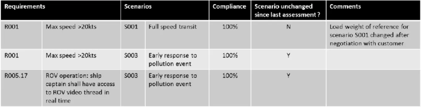
Eventually, the tool may be used to build a complete and consistent compliance matrix, with clear traceability with the design of the ship. An extract of the compliance matrix is provided in Figure 6. The matrix reads from left to right: “requirement R001 / is requested for performing scenarios S001 & S003 / the design is 100% compliant within both scenarios / alert: scenario 1 has changed since last assessment / see comments to evaluate impact”.
Fig. 6 – Compliance matrix extract for requirements R001 and R005.17. Requirements and design changes are monitored with the help of the design management tool described in section 3.2.
The design management tool is useful to fill in the fourth column – scenario changed / unchanged. The novel approach based on “communities of interest” centered around a few operational scenarios makes it much more unlikely that a change in the requirements or in the design goes unnoticed in the compliance matrix – especially so in collaborative engineering environments.
Consistent and provable traceability between the compliance matrix and the design is often difficult to achieve, due to the conceptual and technical heterogeneity between design tools and requirements management tools. The design management tool described in section 3.2 overcomes this difficulty, however the tool is still at a “Proof-Of Concept” maturity level. One of the remaining challenges is to develop a robust, stable and appealing software tool that could be deployed for an actual project and demonstrate “in the field” the benefits of the approach for ship design. Testing the design management tool is one of the tasks foreseen in the HOLISHIP project.
Acknowledgements
This project has received funding from the European Union's Horizon 2020 research and innovation programme under grant agreement n° 689074.
References
Andrews, D., Erikstad, O., 2015. State of the art report on design methodology, 12th International Maritime Design Conference. Tokyo, Japan.
Guegan, A., Rafine, B., Descombes, L., Fadiaw, H., Marty, P., Corrignan, P., 2017. A Systems Engineering approach to ship design, Proceedings of the 8th Complex Systems Design and Management conference. Paris, France.
ISO/IEC/IEEE, 2011. Systems and software engineering - Requirements engineering. Geneva, Switzerland: International Organization for Standardization (ISO)/International Electrotechnical Commission/ Institute of Electrical and Electronics Engineers (IEEE), (IEC), ISO/IEC/IEEE 29148.