UNIVERSITE DE SHERBROOKE Faculte de genie
Departement de genie chimique et de genie biotechnologique
SYNTHESE DE NANOTUBES DE CARBONE MONO-PAROIS
MODIFIES CHIMIQUEMENT PAR LTNJECTION D'AMMONIAC
GAZEUX A CONTRE-COURANT DANS UN PROCEDE
A
PLASMA THERMIQUE INDUCTIF
SYNTHESIS OF CHEMICALLY-MODIFIED SINGLE-WALLED
CARBON NANOTUBES BY COUNTER-CURRENT AMMONIA
GAS INJECTION INTO THE INDUCTION THERMAL PLASMA
PROCESS
These de doctorat Speciality : Genie chimique
A li SHAHVERDI
Jury: Prof. Gervais SOUCY (supervisor) Dr Benoit SIMARD (co-supervisor) Prof. Peter JONES
Prof. Jason R. TAVARES Prof. Jocelyn VEILLEUX
1+1
Library and Archives Canada Published Heritage Branch Bibliotheque et Archives Canada Direction du Patrimoine de I'edition 395 Wellington Street Ottawa ON K 1A0N 4 Canada 395, rue Wellington Ottawa ON K1A 0N4 CanadaYour file Votre reference ISBN: 978-0-494-96309-8 Our file Notre reference ISBN: 978-0-494-96309-8
NOTICE:
The author has granted a non
exclusive license allowing Library and Archives Canada to reproduce, publish, archive, preserve, conserve, communicate to the public by
telecomm unication or on the Internet, loan, distrbute and sell theses
worldwide, for commercial or non commercial purposes, in microform, paper, electronic and/or any other formats.
AVIS:
L'auteur a accorde une licence non exclusive permettant a la Bibliotheque et Archives Canada de reproduire, publier, archiver, sauvegarder, conserver, transmettre au public par telecomm unication ou par I'lnternet, preter, distribuer et vendre des theses partout dans le monde, a des fins com merciales ou autres, sur support microforme, papier, electronique et/ou autres formats.
The author retains copyright ownership and moral rights in this thesis. Neither the thesis nor substantial extracts from it may be printed or otherwise reproduced without the author's permission.
L'auteur conserve la propriete du droit d'auteur et des droits moraux qui protege cette these. Ni la these ni des extraits substantiels de celle-ci ne doivent etre imprimes ou autrement
reproduits sans son autorisation.
In compliance with the Canadian Privacy A ct some supporting forms may have been removed from this thesis.
W hile these forms may be included in the document page count, their removal does not represent any loss of content from the thesis.
Conform em ent a la loi canadienne sur la protection de la vie privee, quelques
form ulaires secondaires ont ete enleves de cette these.
Bien que ces form ulaires aient inclus dans la pagination, il n'y aura aucun contenu manquant.
To my paren ts
"Science is a way o f thinking much more than
it is a body o f knowledge"
RESUME
Les nanotubes de carbone mono-parois (SW CNTs) sont tres peu dispersibles dans les solvants et ils ont besoin d'etre chimiquement modifies avant leur utilisation dans beaucoup d u p lica tio n s. Ce travail se concentre sur la synthese du materiau des SW CNTs chimiquement modifie par une approche in situ. Les objectifs principaux de cette recherche sont : 1) explorer le procede chimique in situ pendant la synthese des SWCNTs et 2) examiner de maniere approfondie l'effet de l'environnement reactif sur les SWCNTs.
Les effets du type de catalyseur et son contenu sur le produit fini des SW CNTs, synthetise par plasma thermique inductif (PTI), ont ete etudies pour remplacer le cobalt (Co) toxique dans la matiere premiere.
A
cet egard, trois melanges de catalyseurs differents (c.-a-d. N i-Y2 0 3, Ni-Co- Y2O3, et NLM0-Y2O3) ont ete utilises. Les resultats experimentaux ont montre que le type de catalyseur affecte la qualite des SWCNTs. Une qualite similaire peut etre produite lorsque la meme quantite de Co est remplacee par le Ni. En outre, des resultats observes dans les travaux experimentaux ont ete explicites par les resultats des calculs thermodynamiques.La thermogravimetrie (TG) a ete utilisee tout au long du travail pour caracteriser les echantillons de SWCNTs. La TG a tout d'abord ete normalisee par l'etude des effets des trois principaux parametres instrumentaux (rampe de temperature, RT, la masse initiate de l'echantillon, MI, et le debit de gaz, D) sur le TonSet et largeur a mi-hauteur (LMH) obtenu a partir de graphiques TG et TG derives de noir de carbone, respectivement. Par consequent, un plan factoriel a deux niveaux a ete prevu. L'analyse statistique a montre que l'effet de RT, MI, et a un degre moindre D est significatif sur la LMH et negligeable sur Tonset.
Une methodologie a ensuite ete developpee sur la base de la synthese des SW CNT en utilisant le systeme PTI, a travers une approche chimique in situ. L'ammoniac (N H3) a ete choisi et injecte a contre-courant dans le reacteur PTI a trois debits differents et en utilisant quatre types de buses differentes. La simulation numerique a indique un meilleur melange du NH3 dans le reacteur PTI lorsqu’une buse particuliere a ete utilisee. Les resultats experimentaux montrent l'augmentation d ’intensite de D-bande dans les spectres Raman d'echantillons SW CNTs lors de l'injection du N H 3. Le NH3 pourrait augmenter la teneur en azote du produit fini de SWCNTs jusqu'a 10 fois. L'echantillon des SW CNTs traitee avec 15% vol de NH3 a montre une dispersion accrue dans le dimethylformamide et l'isopropanol. Les nanostructures de carbone en forme d'oignon et plane, ont aussi ete observees.
Une caracterisation complementaire sur l'echantillon des SW CNTs traites par N H3 a 15% vol., a
indique une modification de la surface des nanotubes, ou des tubes metalliques ont montre une plus grande reactivite avec N H3 que les semi-conducteurs. Le modele, y compris le champ
d’ecoulement thermique du reacteur et la cinetique de decomposition thermique de N H3 a suggere
une modification de surface des SW CNTs en deux etapes dans laquelle les nanotubes reagissent premierement avec les especes interm ediates de H et de N H 2. Le N H3 s ’adsorbe ensuite
chimiquement sur les nanotubes. Le modele a egalement suggere que les especes interm ediates comme le N N H et le N2H2 jouent un role principalement en conduisant la decomposition du N H3
plutot que la modification chimique des SWCNTs.
M o ts -c le s : Nanotubes de carbone mono-parois, Plasma thermique inductif, Synthese, Thermogravimetrie, Cinetique, Mecanique des fluides numerique, Thermodynamique, Modification chimique, Fonctionnalisation
ABSTRACT
Pristine single-walled carbon nanotubes (SW CNTs) are poorly dispersible and insoluble in many solvents and need to be chemically modified prior to their use in many applications.
T his w ork is fo c u se d on the in vestig ation o f the sy n th esis o f ch e m ic a lly m o d ifie d S W C N T s m aterial through an in situ approach. T he m ain o b je c tiv e s o f the p resented research are: 1) to ex p lo re the in situ ch em ic a l p rocess during th e sy n th esis o f S W C N T and 2 ) to c lo s e ly ex a m in e the e ffe c t o f a rea ctive en v iro n m en t on S W C N T s.
E ffects o f th e catalyst ty p e and con ten t on th e S W C N T s fin al product, sy n th e siz e d b y in d u ction therm al p lasm a (IT P ), w e re studied to replace to x ic co b a lt (C o ) in th e fe ed sto ck . In th is regard, three d ifferen t ca ta ly st m ixtu res (i.e. N i-Y2C>3, N i-C o - Y2C>3, and N i-M o -Y2C>3) w ere u sed .
E xperim en tal results s h o w e d that the ca taly st typ e a ffe c ts the quality o f the S W C N T fin al product. S im ilar q u ality S W C N T s can b e p rod uced w h en the sa m e am ount o f C o w a s rep la ced by N i. M oreo ver, th e results ob served in this exp erim en tal w ork w ere further ex p la in e d b y therm od ynam ic ca lcu la tio n results.
T herm ogravim etry (T G ) w a s u sed throughout the w ork to ch aracterize the S W C N T s product. T G w a s firstly standardized b y stu d yin g th e e ffe c ts o f three m ain instrum ental param eters (tem perature ram p, T R , in itial m ass o f the sam p le, IM , and g a s flo w rate, F R ) on th e T onSet and fu ll-w id th h a lf m a x im u m (F W H M ) ob tained from T G and d eriva tive TG graphs o f carbon b lack, resp ectiv ely . T herefore, a tw o -le v e l factorial statistical d esig n w a s perform ed. T h e statistical a n aly sis sh o w ed that the e ffe c t o f T R , IM , and to a lo w e r exten t, F R , is sig n ifica n t o n F W H M and in sig n ifica n t on T onset.
A m e th o d o lo g y w a s then d ev elo p ed b ased u pon the S W C N T s syn th esis u sin g th e IT P sy stem , through an in situ ch em istry approach. A m m o n ia (N H 3) w a s selec ted and cou n ter-cu rren tly in jected into the ITP reactor at three d ifferen t flo w rates and b y fou r d ifferen t n o z z le d esig n s. N u m erical sim u la tio n in d icated a better m ix in g o f NH3 in the ITP reactor w h en a certain n o z z le w a s used. T h e ex p erim en tal results sh o w ed the increase o f D -b an d in ten sity in the R am an spectra o f S W C N T sam p les u pon the NH3 injection . NH3 co u ld in crease the n itrogen co n te n t o f the S W C N T s fin al product up to 10 tim es. T he S W C N T s sa m p le treated w ith 15 vol% NH3 sh o w ed an en h an ced d isp ersib ility in D im eth y lfo rm a m id e and Isop rop anol. O n io n -lik e and planar carbon nanostructures w ere a lso ob serv ed .
C om p lem en tary ch aracterization on the S W C N T sa m p les treated b y 15 vol% N H3 in d ica ted the
surface m o d ifica tio n o f nanotubes. M eta llic tu b es s h o w e d a h igh er reactivity w ith N H3 than
sem ico n d u ctin g o n es. T h e m o d el in clu d in g the reactor th erm o -flo w fie ld and N H3 therm al
d eco m p o sitio n k in etics su g g ested a tw o -step S W C N T su rface m o d ifica tio n in w h ich n anotub es firstly react w ith H and N H2 interm ediates and later, N H3 ch em isorb s o n the nanotub es. T he
m od el also su g g ested that th e interm ediate sp e c ie s , lik e N N H and N2H2, p la y a role prim arily in
d riving the N H3 d eco m p o sitio n rather than the ch em ic a l m o d ifica tio n o f S W C N T s
Keywords: Single-walled carbon nanotube, Induction thermal plasma, Synthesis, Thermogravimetry, Kinetic, Computational fluid dynamic, Thermodynamic, Chemical modification, Functionalization
ACKNOWLEDGEMENTS
This work could not solely be completed through my own effort. From the very beginning o f this work, the help o f other people allowed me to continue the journey till the very end. The least thing that I can do to thank all those helps is to bring their names in this short context.
This work was financially supported by Le Fonds Quebecois de la Recherche sur la Nature et les Technologies (FRQNT) and the Natural Sciences and Engineering Research Council Canada (NSERC).
My special thanks goes to my supervisor Prof. Gervais Soucy without whose help I could not finish the job. His supportive manner along with his kindness was like a driving force which pushed me through the right direction and helped me to overcome the problems that I encountered throughout this work.
I would like to express my gratitude to my co-supervisor Dr Benoit Simard from National Research Council Canada (NRC) whose advices, help and scientific supports made it possible for me to get successfully through the work.
I would like to express my appreciation and gratefulness to Yasaman Alinejad for her help during the synthesis experiments and her support throughout this work.
Dr Alireza Hekmat and Jamie Sharp are acknowledged for English proof reading o f the articles embedded in this thesis, and the rest o f the thesis, respectively. Marc-Andre Coulombe is also acknowledged for French proof reading o f the thesis.
I would like to thank Francis Barrette, whose expertise along with his kindness helped me to overcome many experimental problems which may not be seen through this dissertation. Andre Bilodeau and Carl St-Louis are also acknowledged for the drawing and machining o f the parts and characterization o f the samples, respectively. I am very thankful to Stephane Gutierrez for his help in HRSEM imaging, XRD training and his great support during thermogravimetry analysis. Irene Kelsey and Sonia Blais are also acknowledged. Charles Bertrand and Prof. Nadi Braidy are greatly acknowledged for their help during the HRTEM imaging.
This work could not be done without the help o f our collaborators at National Research Council Canada (NRC). Special thanks to Dr Christopher Kinston for his help in characterization o f our samples. Dr Keun Su Kim is greatly acknowledged for his valuable discussions during the 2D simulation part o f this work, his excellent job in performing the Raman analysis and his time to make me familiar to the basic o f the computational fluid dynamic.
I would like to thank Dr Brahim Selma for his help, valuable discussion and suggestion during the 3D simulation part o f the work.
TABLE OF CONTENTS
CHAPTER 1. Introduction... 1
1.1 Nanotechnology... 1
1.2 Carbon... 1
1.3 Carbon nanotubes... 2
1.4 Thermal plasm a...4
1.4.1 RF induction plasma torch... 5
1.5 Problematic and con text...7
1.6 Project definition and objectives...10
1.7 Original contributions... 14
1.8 Thesis structure... 14
CHAPTER 2. Literature review ...16
2.1 Carbon nanotubes... 16
2.2 SWCNTs structure... 16
2.3 Carbon nanotubes properties...19
2.3.1 Mechanical properties... 20
2.3.2 Electronic properties... 22
2.3.3 Thermal properties... 23
2.3.4 Chem istry... 24
2.4 SW CNT applications... 28
2.4.1 CNTs-polymer com posites... 28
2.4.2 Electronic d e v ic e s ... 29
2.4.3 Tips probe imaging... 30
2.4.4 S en sors...31
2.5 SW CNT synthesis m ethods... 31
2.5.1 Arc-discharge... 32
2.5.3 Chemical vapor deposition (C V D )... 33
2.5.4 Induction thermal plasma (IT P )...34
2.6 SWCNT Growth m echanism s... 37 2.6.1 Vapor-Liquid-Solid m echanism ... 37 2.6.2 Scooter m echanism ...38 2.6.3 Solid-Liquid-Solid m echanism ... 39 2.7 SWCNT chemical m odification... 40 2.8 Conclusion... 49
CHAPTER 3. Material and m ethod... 51
CHAPTER 4. Synthesis o f single-walled carbon nanotubes using induction thermal plasma technology with different catalysts: thermodynamic and experimental stu d ies... 57
4.1 R esum e... 60
4.2 Abstract... 60
4.3 Introduction... 61
4.4 Thermodynamic calculations... 62
4.5 Experimental procedure and setu p ...63
4.6 Results and discussion...65
4.6.1 Thermodynamic study... 65
4.6.2 Experimental results...70
4.7 Conclusion... 74
CHAPTER 5. Thermogravimetrie analysis o f single-walled carbon nanotubes synthesized by induction thermal plasm a...76
5.1 R esum e... 77
5.2 Abstract... 77
5.3 Introduction... 78
5.4 Experim ental...80
5.4.1 Synthesis and Purification... 80
5.4.3 TGA procedure...81
5.4.4 Sampling...81
5.5 Results and discussion...82
5.5.1 Sampling...82
5.5.2 Statistical stu d y ...84
5.5.3 Purity evaluation...8 6 5.6 C onclusions... 91
CHAPTER 6. Counter-current ammonia injection flow during synthesis o f single-walled carbon nanotubes by induction thermal plasm a... 92
6.1 R esum e... 93
6.2 A bstract... 94
6.3 Introduction... 95
6.4 Thermodynamic calculation... 97
6.5 Experimental setup and procedure...97
6 . 6 Computational fluid dynamic (CFD) m odel...101
6.7 Results and discussion...104
6.7.1 Thermodynamic calculation resu lts...104
6.7.2 Experimental results...106
6.7.3 CFD simulation results... 115
6 .8 Conclusion...117
CHAPTER 7. Effect o f ammonia gas addition to the synthesis environment o f single-walled carbon nanotubes on their surface chem istry... 119
7.1 R esum e... 120
7.2 Abstract... 121
7.3 Introduction... 121
7.4 Experimental setup and procedure...125
7.5 Numerical m odeling... 127
7.6.1 Experim ental...134
7.6.2 Sim ulation... 142
7.7 Conclusion... 149
CHAPTER 8. Overall conclusions and future w o rk ... 151
8.1 Conclusions generates... 151
8.2 Overall con clusion s... 155
8.3 Future w o rk ... 158
APPENDIX A ...160
APPENDIX B ...161
APPENDIX C Raman spectroscopy o f S W C N T s...162
LIST OF FIGURES
Figure 1.1 Five different allotropes o f carbon...1
Figure 1.2 Number o f annual publications on CNTs per year, from 1992-2012...3
Figure 1.3 Different types o f plasmas from naturally generated to man-made: 1) Solar corona, 2) Ionosphere, 3) Flames, 4) Thermonuclear fusion plasma, 5) Glow and RF discharges, Fluorescent lamp, 6) High pressure Arc and RF discharges, Shock w aves...4
Figure 1.4 Schematic o f an RF induction plasma torch along with its typical temperature profile...6
Figure 2.1 Rolling up a graphene sheet to SW CNT... 16
Figure 2.2 Schematic o f three different types o f SWCNT, (a) armchair, (b) zigzag, and (c) chiral...18
Figure 2.3 Unit cell o f CNT on un unrolled graphene sheet, with the chiral vector, Ch, and its perpendicular translation vector, T ... 18
Figure 2.4 Diagrams o f (a) metallic (5,5) SWCNT, (b) pyramidalization angle (0p) and, (c) the 7i-orbital misalignment angle ( 0 ) along the C1-C4 bond in the (5,5) SW CNT and its capping fullerene C6o... 26
Figure 2.5 Arc-discharge apparatus for the synthesis o f SW CNT... 32
Figure 2.6 Oven laser-vaporization apparatus for synthesis o f SW CNTs... 33
Figure 2.7 CVD apparatus for the synthesis o f SW C N T s...34
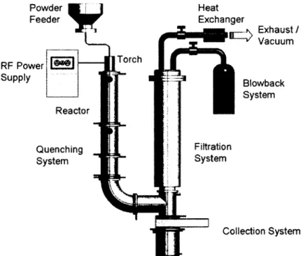
Figure 2.8 Schematic o f ITP setup used to produce high quality SW CNTs containing soot at large scale... 35
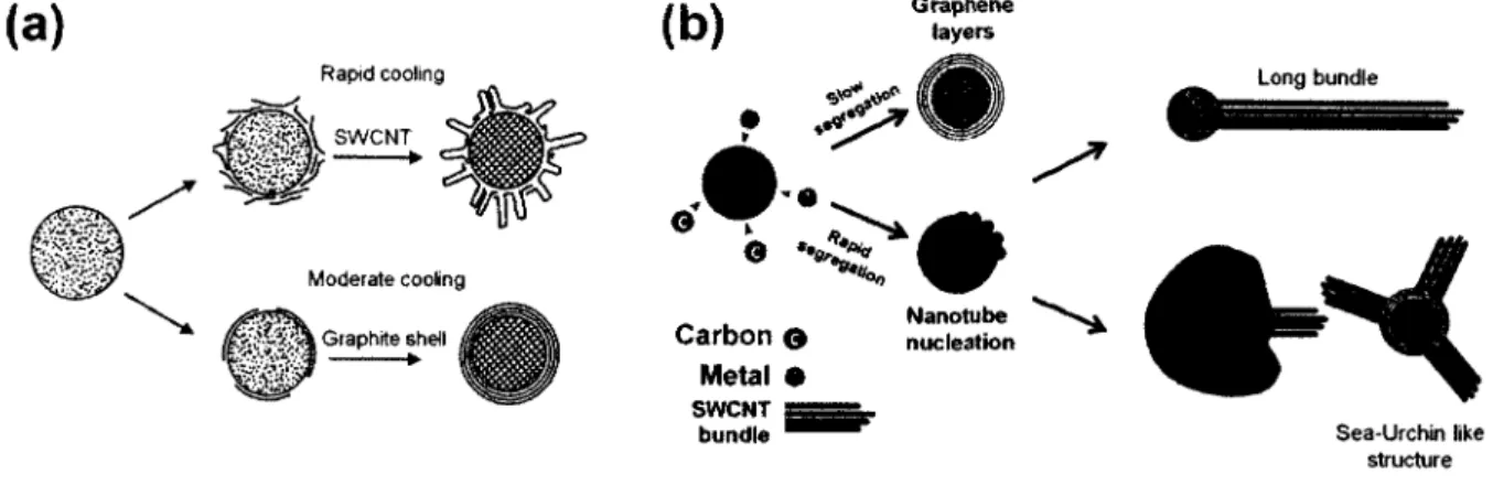
Figure 2.9 (a) Schematic o f the nucleation and growth o f SWCNT in high temperature method, and (b) extended VLS model. Either long bundle or sea-urchin like structure has been experimentally observed... 38
Figure 2.10 SWCNT growth mechanism explained by "Scooter" m odel... 39
Figure 2.12 Different classes o f SW CNT functionalization (a) defect site chemistry: 1) open-end, 2) vacancy, 3) structural defect (b) side-wall, (c) endohedral and (d)
End-cap... 41
Figure 2.13 Various covalent SW CNT functionalizations... 45
Figure 2.14 SWCNT functionalization through (a) oxidation or (b) fluorination...48
Figure 3.1 Lab-scale SWCNT synthesis system (a) original setup, (b) modified setup... 51
Figure 3.2 Schematic diagram o f the modified SWCNT synthesis setu p ... 52
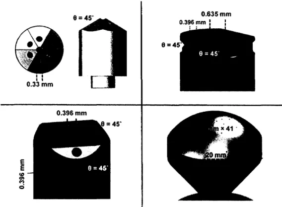
Figure 3.3 Four different nozzles used for counter-current injection of ammonia...56
Figure 4.1 Schematic diagram o f an ITP system designed for large-scale synthesis o f high quality S W C N T ...64
Figure 4.2 Thermodynamic equilibrium composition in gas phase (left-side) and liquid solution phase (right- side) o f (a), (b) MIX 1, (c), (d) MIX 2 and (e), (f) MIX 3 ...65
Figure 4.3 Superimposed liquid solution phase o f MIX 1 (dashed-line) and MIX 2 (solid-line) ...6 8 Figure 4.4 MIX 4 thermodynamic equilibrium compositions in (a) gas phase and (b) liquid solution p h a se...6 8 Figure 4.5 Thermodynamic equilibrium composition in gas phase (left side) and liquid solution phase (right side) o f (a) MIX 5 and (b) MIX 6...69
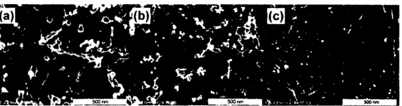
Figure 4.6 HRSEM images o f SW CNT samples synthesized with (a) MIX 1, (b) MIX 2, (c) MIX 3, (d) MIX 4, (e) MIX 5 and (f) MIX 6 ... 71
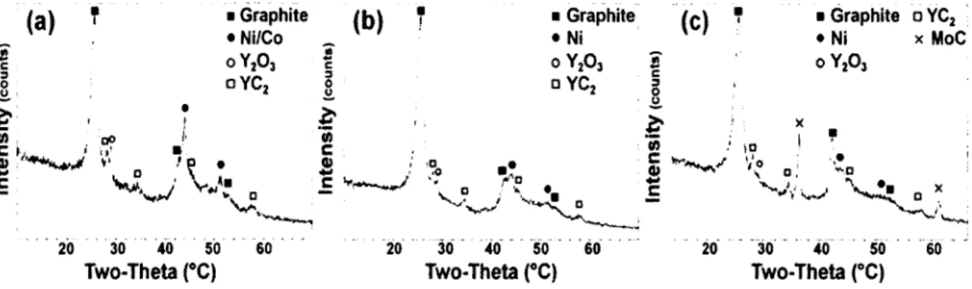
Figure 4.7 XRD patterns o f SW CNT samples synthesized with (a) MIX 1, (b) MIX 2, and (c) MIX 3 ... 72
Figure 4.8 Axial profile o f temperature along the centreline o f the reactor. Black and white circle denote the eutectic temperature o f Mo-C and Ni-C/Co-C systems, respectively...73
Figure 4.9 TG graphs o f SW CNT samples synthesized using M IX 1 (dashed-dotted line), MIX 2 (dashed line) and MIX 3 (solid line)... 74
Figure 5.1 TG graphs o f CB (a) original sample (b) dried sam ple...82
Figure 5.3 Normal plot o f residual for FW H M ...85 Figure 5.4 Half-normal probability plot for FW H M ...8 6
Figure 5.5 TG/DTG graphs o f as-produced SWCNT with induction thermal plasm a...8 8
Figure 5.6 TGA/DTG graphs o f thermally oxidized SW CNT sample at 350 °C ...8 8
Figure 5.7 HRSEM images o f induction thermal plasma-grown SWCNT at three different level o f purities (a) as-produced sample (low purity) (b) thermally oxidized sample (mid purity) (c) sample treated with strong acid (high purity)...89 Figure 5.8 DTG graph o f highly purified thermal-plasma grown SWCNT along with that
o f its Guassian peaks. The graph is deconvoluted into 7 peaks... 89 Figure 5.9 TGA o f nano-metric nickel (clOOnm) along with that o f yttrium oxide
(<50 n m )... 90 Figure 6.1 Schematic o f an induction thermal plasma unit o f SW CNT synthesis developed
and modified for an effective continuous NH3 injection...99 Figure 6.2 Computational domains considered for CFD calculations (a) no nozzle, (b)
20 mm nozzle shown in Figure 6.1 ... 102 Figure 6.3 Gas phase thermodynamic equilibrium compositions for a mixture system o f
C /N i/Y2O3/S /N H3 (9 7 .7 /1 .2 / 0.4/ 0.7: at %/0.4 mole) at 6 6 . 6 k P a ... 105
Figure 6.4 (a) Solid phase thermodynamic equilibrium com positions for a mixture system o f C /N i/Y2O3/S /N H3 at 6 6 . 6 kPa (b) XRD pattern o f SWCNT sa m p le ... 106
Figure 6.5 Concentration profile of Ar, He and NH3 in the exhaust gas quantified by mass spectrometer during N H3 injection process...108
Figure 6 . 6 Mass spectra o f the SWCNT synthesis exhaust gas before (solid) and after (dashed) injection o f NH3 into the induction thermal plasma sy stem ...109 Figure 6.7 Raman spectra for raw SW CNT (run=7) and that exposed to high temperature
NH3 (r u n = l-6). The spectra are normalized to the G-band and sorted in order o f D-band intensity (A^xt = 514.5 n m )... 111 Figure 6 .8 TEM images o f (a) raw SWCNT sample (b) SW CNT sample exposed to N H3
(15 vol %), (c), (d), (e) and (f) spots indicating other morphologies not seen in the raw SW CNT sample, (scale bar in inset= 10 nm)... 114
Figure 6.9 Long-term dispersibility behaviour o f (a) raw SWCNT, (b) NFL-treated S W C N T ...115 Figure 6.10 Calculated N H3 mole fraction, temperature and velocity profiles for two
different types o f injection, at 6 6 . 6 kPa (a) without nozzle and (b) with nozzle... 117 Figure 7.1 Schematic diagram o f the ITP synthesis system o f chem ically-m odified
SW CNT with its main components: 1) ITP torch,2) ITP reactor, 3) filtration system, 4) powder feeder , 5) mass spectrometer and 6) product collection bucket... 127
Figure 7.2 Computational domain considered for numerical sim ulation... 128 Figure 7.3 (a) TG-DTG graph o f NtL-treated SW CNT sample under desorption
conditions, (b) 3D contour map o f the FTIR spectra obtained from the evolved gas during TG desorption p rocess... 134 Figure 7.4 FTIR spectra o f extract gas @ 180 °C (a) low-frequency region (500-
1 700 cm"1), (b) mid-frequency region (2 000-2 500 cm '1), (c) High-frequency region (2 500-4 000 cm '1). §, ¥ and n characters denote the presence o f species other than CO2 and H2O ... 135 Figure 7.5 Raman spectra for raw (dotted-line) and NH3-treated (solid-line) SW CNTs at
XeXt.= 632.8 nm. (a) Complete Raman scattering region is normalized to the cqg+ (b) RBM region: the spectra are normalized to the RBM feature at 180 cm"1 (c) Tangential mode region, the low energy ends are identified with dashed circle... 139 Figure 7.6 Raman spectra for raw (dotted-line) and NH3-treated (solid-line) SW CNTs at
Xext = 514.5 nm. (a) Complete Raman scattering region is normalized to the cog+ (b) RBM region: the spectra are normalized to the RBM feature at 168 cm '1. (c) Tangential mode region, the low energy ends are identified with dashed c ir c le ... 140 Figure 7.7 Raman spectra for raw (dotted-line) and ammonia-treated (solid-line) SW CNTs
at Xext.= 780 nm. Complete Raman scattering region is normalized to the (0g+... 141 Figure 7.8 FTIR spectra o f SWCNT samples (a) raw SW CNT (b) N H 3-treated S W C N T 141
Figure 7.9 Temperature (top) and stream-function (bottom) contours in (a) the ITP torch, (b) the ITP reactor without NH3 opposed-flow in jection ...143 Figure 7.10 Temperature (top) and stream-function (bottom) contours o f ITP reactor with
opposed-flow N H3 injection...144
Figure 7.11 Radial temperature profile at 2 cm far from the base o f the ITP reactor before (dotted-line) and after (solid-line) NH3 injection...145 Figure 7.12 Calculated mole fraction o f intermediate species above the N H3 injection point
at the base o f ITP reactor...148 Figure 7.13 Calculated mole fraction o f N H3 and its decomposition products: N2 and H2
LIST OF TABLES
Table 1.1 Different allotropes o f carbon... 2
Table 1.2 Typical characteristics o f DC plasma and RF induction torches... 5
Table 2.1 Physical properties o f individual SW CN T ...20
Table 2.2 Advantages and disadvantages o f various SWCNT synthesis methods... 36
Table 3.1 ITP operating conditions during the preheating process... 54
Table 3.2 Typical ITP operating conditions during the synthesis o f SW CNT... 54
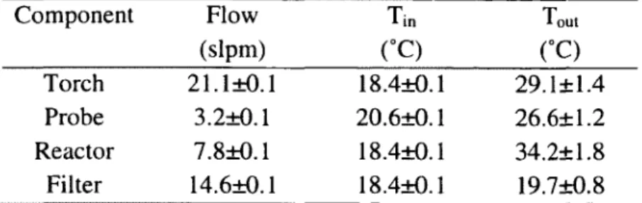
Table 3.3 Cooling water flow rate, inlet and outlet temperature o f each ITP com ponent 55 Table 4.1 Feedstock material content in weight percent (wt. %) used for the synthesis o f S W C N T ...63
Table 4.2 Properties o f the materials used for the production o f S W C N T ... 64
Table 4.3 Quality assessments o f SWCNT synthesized with different catalysts mixtures 71 Table 5.1 23' 1 Statistical factorial design...81
Table 5.2 Two responses variable (FWHM and Tonset) obtained from T G ...84
Table 5.3 ANOVA for selected factorial m odel...85
Table 6.1 Operating conditions o f induction thermal plasma system used in this work... 99
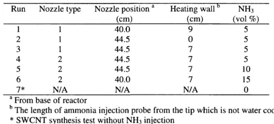
Table 6.2 Experimental conditions o f high temperature NH3 injection during the synthesis o f SW CNT by induction thermal plasma... 100
Table 6.3 Governing equations used in the 3D sim ulation... 103
Table 6.4 Boundary conditions applied in 3D simulation...103
Table 6.5 Decomposition history o f NH3 in ITP system at different plasma powers without feedstock injection...106
Table 6 . 6 Elemental nitrogen content in the SW CNT samples after exposed to ammonia during synthesis p rocess...1 1 0 Table 7.1 Operating conditions used for the ITP torch... 126
Table 7.2 Boundary conditions o f ITP reactor... 131
Table 7.3 Detailed reaction mechanism and rate parameters, k=ATn exp (-E/RT) (cm3/m ole.sec)...132
LIST OF SYMBOLES
Ag tangential component o f magnetic vector potential (T m)
C D drag coefficient C h chiral vector
c P
specific heat o f fluid at constant pressure (J/kg K)C p constant in turbulence model
C, constant in turbulence model
c 2
constant in turbulence modelc p specific heat o f particle injected (J/kg K) Q volume fraction constant
Q time scale constant
D k binary diffusion coefficient o f species
k
(m2/s)Eg tangential component o f electric field (V/m)
Fl Lorentz force (N/m 3)
f frequency applied to RF induction coil (Hz)
8 ° standard free Gibbs energy
G , product o f the turbulent viscosity and viscous dissipation terms (kg/m s3)
h
specific enthalpy o f fluid (J/kg)hc
heat transfer coefficient o f fluid (W/m2 K)Hr radial component o f magnetic field intensity (A/m) Hz axial component o f magnetic field intensity (A/m)
Jcoil coil current density (A/m 2) Jind induced current density (A/m 2) K turbulent kinetic energy (m2/s2)
kB
Boltzmann constant (J/K) m mass flow rate (kg/s)P ohm heat generation by ohmic heating (W /m3) P static pressure o f fluid (Pa)
Pr Prandtl number o f fluid Pre constant in turbulence model Pr* constant in turbulence model Pr, turbulent Prandtl number
R universal gas constant (J/mol K)
R ra d radiational loss taken into account by using net em ission coefficient (W /m3)
Sc, turbulent Schmidt number
T temperature o f fluid (K)
T translation vector
T onset temperature at which material starts to lose weight U axial velocity o f fluid (m/s)
V radial velocity o f fluid (m/s) V kinematic viscosity (m2/s) w swirl velocity o f fluid (m/s)
Yk mass fraction o f species k ITP induction thermal plasma TG thermogravimetry
Greek letters
£ dissipation rate o f turbulent kinetic energy (m2/s 3) K laminar thermal conductivity o f fluid (W/m K)
Keff effective thermal conductivity o f fluid (W /m K)
K, turbulent thermal conductivity o f fluid (W/m K)
Yi activity coefficient
P laminar viscosity o f fluid (kg/m s) Me# effective viscosity o f fluid (kg/m s)
P< turbulent viscosity o f fluid (kg/m s)
Po magnetic permeability o f free space (N /A 2)
? length fraction o f the fine scales: * denotes fine-scale quantities
P mass density o f fluid (kg/m3)
a electrical conductivity ( Q1 m '1) T viscous stress tensor (N/m 2)
CHAPTER 1. Introduction
1.1 Nanotechnology
The term ‘nano’ in nanotechnology originates from the Greek word Nanos meaning dwarf. In metrology, 1 nanometer (nm) is equal to lx lO' 9 m. Hence in material science, nanotechnology deals with a variety o f structures o f matter having at least one dimension in the nanometric range [Poole and Owens, 2003],
1.2 Carbon
Carbon, one o f the most abundant elements, is sixth in the periodic table with an atomic mass o f 12.011 g and an atomic number 6. Carbon is considered a non-metallic element with a Is2
2 2
2s 2p electron configuration. It possesses four electrons in the valance shell and can hold up to four extra electrons to become saturated. Therefore, carbon forms many versatile compounds with different size and shapes. Three main natural allotropes o f carbon are amorphous carbon, graphite, and diamond. There are also different synthetic allotropes o f carbon. Among those, fullerene and carbon nanotubes are the most well-known species. Figure
1.1 illustrates these five different allotropes o f carbon.
Amorphous
Diamond
Graphite
Fullerene
Nanotube
Figure 1.1 Five different allotropes o f carbon.
Fullerene and Nanotube structures were drawn using Nanotube Modeler© JCrystalSoft v. 1.7 .3
From a chemical point o f view, carbon atoms bind together in a planar sp2 (C=C) or spatial sp3
(C-C) hybridization. In perfect graphite, fullerene, and nanotube, carbon atoms bind with sp2
hybridization while in diamond and amorphous carbon, the hybridization is sp3. From a physical point o f view, carbon can make a OD, ID, 2D, or 3D spatial configuration which makes it a very interesting element to study. Four main allotropes o f carbon are summarized in Table 1.1.
Table 1.1 Different allotropes o f carbon
Allotrope Dimension Hybridization
Fullerene 0D sp2
Nanotube ID sp2
Graphene* 2D sp2
Diamond 3D sp3
* A single-layered graphite
The nature o f bonding o f carbon atoms and their spatial configurations affect drastically the chemical and physical properties o f each allotrope. For instance, graphite with the 3D
'y
configuration and sp hybridization has soft mechanical strength compared to that o f diamond having an extraordinary strength, with the 3D configuration and the sp3 hybridization.
1.3 Carbon nanotubes
The first evidence o f carbon nanotube may have been observed in 1952 by Radushkevich and Lukyanovich [Monthioux and Kuznetsov, 2006]. They reported the formation o f thread-like nuclei and co-twisted threads during the production o f carbon black deposits on Fe, in the presence o f flowing CO gas at 600 °C. However, they implied no explanation for such an observation and brought no evidence for such thread-like structures to be carbon nanotube. This is due to the low resolution o f transmission electron microscope (TEM) at that time. Two decades later, in an attempt for the synthesis o f carbon fiber by pyrolysis o f benzene and ferrocene, single- and multi-shell hollow tubular carbon structures with diameters from few to tens o f nanometers were observed [Oberlin et al., 1976; Terrones, 2003]. At that time, the research community was interested in micron size materials, so no attention was drawn to this interesting observation. Therefore, the discovery o f carbon nanotube has been ascribed to
Sumio Iijima who was the first to publish an article reporting the formation o f helical microtubules o f graphitic carbon with diameters ranging from 4 to 30 nm and 2 to 50 in number o f graphitic layers. This was discovered during his attempts to synthesize fullerene using an arc-discharge evaporation method [Iijima, 1991]. His report clearly indicated a definitive method for the synthesis o f what is called today ‘multi-walled carbon nanotube’ (MWCNT). Two years later, in 1993, Iijima and Ichihashi [Iijima and Ichihashi, 1993] and Bethune et al. [Bethune et al., 1993] reported for the very first time the synthesis o f single shell carbon nanotubes o f ~ 1 nm diameter, which was later named ‘single-walled carbon nanotube’ (SWCNT). Both o f these newly engineered nanostructures o f carbon have garnered immense attention from the carbon research community due to their very unique structures: a very high aspect ratio making them very close to an ideal ID structure. In the same era, researchers from other fields have also been attracted to work on carbon nanotubes (CNTs) leading to grow this new field o f research much faster than expected. In the past twenty years, a large amount o f work has been devoted to the optimization and improvement o f the synthesis methods, characterization, chemistry, and applications o f CNTs. Figure 1.2 represents the contribution o f the research community in the field o f CNTs for the past twenty years. As shown in Figure 1.2, the number o f published scientific articles has exponentially increased over the past two decades implying the importance o f CNTs in materials science and showing that the field o f carbon nanotubes is very active.
x 10> 10 M 9
.1 8
<0 O 7 ■Q 8 3 a. 5 o 4 0) 3 ■Q 3E 2
3z
1 0 2000 2005 2010 2015 1990 1995Year
Figure 1.2 Number o f annual publications on CNTs per year, from 1992-2012. Data collected from Science Finder database
1.4 Thermal plasma
Plasma is the fourth state o f matter constructed essentially by atoms (neutral particles), ions and electrons. The main characteristic o f plasma is that it is electrically conductive due to the considerable number o f free charge carriers. Interestingly, plasma o f certain gases (e.g., H2) at a high temperature (106 K) can be even more electrically conductive than metals at room temperature. Plasmas can be placed into two distinct groups: i) thermal plasma, and ii) non- thermal plasma. In thermal plasma, the electron temperature approaches the temperature o f the heavy particles (i.e., neutrals and ions) and therefore, the plasma is in a local thermodynamic equilibrium (LTE). W hile in non-thermal plasma, the electron temperature is much higher than the temperature o f the heavy particles and therefore this type of plasma, which strongly deviates from kinetic equilibrium, is not at LTE [Boulos et al., 1994; Boulos, 1991]. Accordingly, non-thermal plasma is also called non-equilibrium plasma. Different types of plasmas exist which are either naturally generated or man-made. They can be classified according to the electron temperature and density. Som e o f these natural or man-made plasmas are illustrated in Figure 1.3.
5 4 3 2 1 0 o> , a -> •2 8 10 12 14 16 18 20 22 24 26 28
Log electron density (nr3)
Figure 1.3 Different types o f plasmas from naturally generated to man-made: 1) Solar corona, 2) Ionosphere, 3) Flames, 4) Thermonuclear fusion plasma, 5) Glow and RF discharges, Fluorescent lamp, 6) High pressure Arc and RF discharges, Shock waves.
Thermal plasma technology covers a wide range o f applications including: i) thermal plasma coating such as plasma spraying, wire arc spraying, and thermal plasma chemical vapor deposition, ii) cutting, iii) fine and ultrafine powder synthesis, iv) powder densification and spheroidization, v) waste-treatment vi) thermal plasma metallurgy [Fauchais and Vardelle, 1997; Pfender, 1999]. The main devices widely used in the aforementioned applications for generating thermal plasma are direct current (DC) plasma torches, and radio frequency (RF) inductively coupled plasma torches. Choosing plasma-generating device for a certain application is tightly related to the processing condition and a good compatibility between the processing requirements and the characteristic o f the device. The main characteristics o f these two thermal plasma-generating devices are summarized in Table 1.2.
Table 1.2 Typical characteristics o f DC plasma and RF induction torches
Characteristics RF induction torch DC plasma torch
Total gas flow rate H ig h c Low (<100 slp m a)
Commonly used gases W ide range o f gases Ar, He, H2, N2, oxidizing with almost no gas (only with cold
lim itationc copper electrod es)a
Maximum temperature (K) 1 0 0 0 0“ 1 2 0 0 0a
Operating pressure (kPa) 2 5 -4 0 0 c 2 0 -5 0 0 c
V elocity (m/s) 1 0 - 2 0 a 400-600 a
Residence time (ms) 1 0-2 0a 0.5 a
Hot core volume (cm 3) 60-300 b ~ 0.4 a
Average energy efficiency (%) 5 0 c 70 c
Local power density Low a High a
a [Boulos, 1991] b [Boulos, 1992]
c [Fauchais and Vardelle, 1997]
1.4.1 RF induction plasma torch
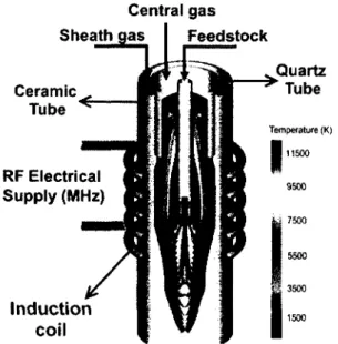
As shown in Figure 1.4, the RF induction plasma torch mainly consists o f three concentric tubes: (i) a confinement tube which is constructed either by quartz (Power plate < 30 kW) or ceramic (30< Power plate <150 kW) and surrounded by 3 to 7 turns of the induction coil, (ii) a quartz tube separating sheath gas from central gas, and (iii) an injection probe [Fauchais and Vardelle, 1997]. The role o f the turned-coil is to generate a magnetic field inside the ceramic tube. The upper part o f the torch is the gas distributor that introduces the plasma-forming
gases into the torch. The sheath gas is employed in order to protect the confinement tube’s wall from hot plasma gas. The plasma-forming gas, the central gas, is introduced into the torch from the center. An adjustable water-cooled probe is placed at the centre o f the ceramic tube for effective introduction o f gaseous, liquid, or solid feedstock materials into the plasma discharge at the center. To sustain the plasma, a minimum amount o f power has to be applied which depends on the frequency o f the power supply and also on the gas composition [Fauchais and Vardelle, 1997]. The schematic diagram o f the RF induction plasma torch along with its typical temperature profile is depicted in Figure 1.4. Compared to DC plasma torches, RF induction torches have some advantages [Boulos et al., 1994; Fauchais and Vardelle,
1997] which make them suitable especially in the nanostructure synthesis, these include:
• A good flexibility in choice o f plasma forming gases from inert to very reactive ones. • A better mixing o f reactants in the plasma due to the axial injection.
• A longer residence time allowing for a larger amount o f feedstock to be treated. • A large plasma volume with a longer residence time makes the RF induction torch
suitable for in-flight melting process o f metals and ceramic powders at high throughput.
Central gas
Sheath gas Feedstock
Ceramic Tube RF Electrical Supply (MHz) Quartz Tube Temperature (K) 11500 5 3500 In d u c tio n coil
Figure 1.4 Schematic o f an RF induction plasma torch along with its typical temperature profile.
1.5 Problematic and context
Carbon nanotubes hold great promise in many applications such as polymer com posites, as reinforcements, in nanoelectronic devices, as electron emitters and field em ission transistors, in energy storage, probes, sensors, and biological applications such as drug delivery and tissue engineering [Ajayan and Zhou, 2001; Baughman et al., 2002; Eder, 2010; Endo et al., 2008; Harris, 2009; Krueger, 2010; Popov, 2004]. This is because o f the outstanding physicochemical properties o f carbon nanotubes along with their unique ID structure. However, there has been a big obstacle in taking advantage o f these unique properties in target applications. It is their poor processability. There has been an immense amount o f research in the past two decades on functionalizing CNTs and up to now, a wide variety o f methods has been proposed and developed for effective surface functionalization in order to enhance their solubility, functionality, and processability. Most o f these methods are based on wet chemistry (also known as solution-based chemistry) in which usually milligram amounts o f CNTs material is subjected to higher amounts o f reactive chemicals. Hence, it is a batch process. The first problem which arises from wet chemistry-based methods is the considerable amount of the waste materials that they produce. In addition to the resulting low yield o f the process which is mainly due to the partial loss o f the starting sample during the process, the waste products have to be further treated. The waste production o f these methods w ill be much more intense when the scaling up is taken into consideration. These methods are considered complex since they follow several time-consuming steps such as premixing, stirring, centrifuging, filtering, rinsing and drying. Besides the additional cost o f each step to the final CNTs products, follow ing all these steps at the optimum conditions is not an easy task and may be the main reason why these methods are mostly limited to the laboratory scale. An alternative functionalization process is cold plasma technology which has been shown in the literature to be effective for the surface chemistry o f CNTs [Khare et al., 2005; Khare et al., 2002b; Khare et al., 2002a; Khare et al., 2004b; Khare et al., 2004a; Plank et al., 2003; Valentini et al., 2005]. Beside the advantages it offers such as fast reaction time (in an order of several minutes) and a cleaner process, this method is subjected to some issues:
• Scaling up is a challenging task.
• Controlling operating parameters for the best chemistry is not an easy task since the reaction takes place only on the surface o f the sample.
• The pricey operation unit adds extra cost to the final CNTs products. • Limited chemistry
Although there has been a large number o f work on the chemical modification o f SWCNTs materials, the proposed methods including wet chemistry and cold plasma are essentially post treatment processes. Post-processing adds extra cost to the final product and in the case of CNTs, the functionalization process can augment the price o f the final product up to seven times (source: Sigma-Aldrich®).
Worldwide use o f SWCNT materials in many applications urges developing reliable, safe and continuous synthesis method at a large scale. Since their discovery in 1993, it has been a real challenge to design and develop a synthesis method answering all these needs. The first introduction o f an FTP synthesis system [Kim et al., 2007] demonstrated a promising method for continuous large scale synthesis o f SW CNT materials with high production rate (i.e., kg/day) using a 60 kW power unit. Moreover, the only limitation for scaling up FTP synthesis system is mainly related to the available highest power unit in the market working at 1MW (TEKNA Inc. CAN A DA ). A simple calculation indicates that the proposed ITP system has the potential to be roughly scaled up by a factor o f 16 to produce a few tons o f SW CNT per year which w ill be a real breakthrough in the carbon nanotube market. However, there are concerns related to the health issues o f nanomaterials (e.g. the effect o f SWCNTs on humans) which forces reconsideration o f the minimization o f nanomaterials exposure in the work place. Therefore, in designing and developing future synthesis procedures one must also consider occupational health and safety (OHS) issues in addition to the technical priorities [Alinejad et
al., 2012a]. The early study showed that high quality SW CNTs can be synthesized by a
mixture o f solid carbon black and metal catalysts in which Co is one o f the catalysts forming the mixture [Kim et al., 2007]. Although synthesizing high quality SW CNTs is o f great interest, a recent toxicological study has indicated high cytotoxicity o f cobalt particles [Alinejad et al., 2012a]. Using highly toxic cobalt in the feedstock o f SW CNT materials,
which will remain in the final product, has been the major bottleneck o f the product. In addition to the use o f non-toxic materials in the feedstock, the setup itself plays an important role in increasing OHS risks. The first setup used by Kim et al. (2007) is not a closed system meaning that the exposure is quite probable in the work place especially during the sample recovery and the cleaning process. Scaling up such a system means much higher exposure risks; too high to be tolerated by workers and authorities.
In carbon nanotube material synthesis, characterization o f the final product is an important step. Som e characterization techniques are very specific while others are more general and used more frequently. Among these general techniques, thermogravimetry (TG) is one which is frequently used for carbon nanotubes materials mainly due to its simplicity in characterizing the metal content [Geng et al., 2002; Moon et al., 2001], purity [Itkis et al., 2005], and thermal stability [Landi et al., 2005; Lima et al., 2009; Yu et al., 2005]. Although it was one o f the first techniques used to characterize CNTs [Pang et al., 1993], no systematic study has been performed on this technique in order to closely examine the influence o f instrumental parameters and also the sampling on the final results. In reviewing the literature, it was found that TG parameters vary amongst studies, and in some studies go unmentioned, implying that their direct effect on the final results of TG has not fully been considered. For instance, the initial mass o f CNT samples characterized using TG has been reported in a wide range from 1 to 10 mg [Itkis et al., 2005; Landi et al., 2005; Yu et al., 2005], Additionally, other studies have not mentioned the applied gas flow rate at all [Hu et al., 2003; M cKee and Vecchio, 2006]. In order to widely use the TG technique for CNT materials and produce reliable TG data, its standardization is essential and must be considered [Decker et al., 2009]. Moreover, using TG for the purity evaluation is o f great interest, compared to other techniques such as high resolution scanning electron microscopy (HRSEM) or near-infrared (NIR) spectroscopy, because it is the only technique that can be used for direct purity evaluation o f SWCNT materials. However, TG is very straight forward and promising only when the CNT samples show a simple TG behavior. In the case o f as-produced SWCNT materials, including those grown by the ITP method (used in this project), that are not highly pure and show a very com plex TG behavior [Kim et al., 2009a], the possible use o f TG for purity evaluation is hindered.
1.6 Project definition and objectives
The main objective o f the present work is to modify in situ the chemistry o f SW CNTs produced using the TCP system by studying the effect of the ammonia gas addition into the SWCNT synthesis environment. By achieving this objective, several advantages are believed to be obtained compared to conventional wet chemistry processes and cold plasma technology. Developing in situ chemistry enables minimization o f costs o f the SWCNT functionalization process since the whole process takes place at the same time and same place as the synthesis process. In situ process is expected to also increase the overall energy efficiency o f the synthesis process since the heat o f reaction is supplied by the main plasma gas stream in the TCP reactor. Towards the main objective, several specific objectives are taken into consideration: i) To investigate the possible effects o f the reactive synthesis environment on the morphology and structural quality o f SWCNT final product, ii) to study the reactivity of SW CNTs material with ammonia at high temperature in the TCP reactor, iii) to investigate the effect o f different types o f ammonia injections on the thermo-flow field o f the TCP reactor by a 3D model, and iv) to develop a full 2D model based on coupled computational fluid dynamic (CFD)- kinetics o f ammonia thermal decomposition in order to predict the concentration profile o f reactants during decomposition o f ammonia in the TCP reactor.
To perform in situ chemistry in the TCP system, ammonia is chosen as the reactive gas. The choice o f ammonia is made based on the following criteria:
• The effectiveness o f ammonia in functionalizing SW CNTs has been already proven [Felten et al., 2005; Khare et al., 2004b].
• The presence o f N/H-containing functional groups has valuable applications in biology and polymer com posite [Chen et al., 2004; Ramanathan et al., 2005a; Ramanathan et
al., 2005b; Richard et al., 2003].
• N/H functional groups can act as anchor sites for grafting o f other groups as well. • Ammonia is used in the gas phase therefore less influence is expected on the thermo
• Thermodynamic and transport properties o f ammonia along with its decomposition kinetics have been widely studied and established enabling a full model o f reaction system to be developed.
• Gas phase chemicals are preferred due to a better control of the m ixing process in the ITP reactor.
In defining the in situ SWCNTs chemical modification project, some hypotheses are initially considered in order to approach the best practice for effective chemistry. To our best knowledge, the proposed project is new and no similar work has been performed so far by other research groups on SWCNTs. Therefore, the parameters affecting this process are not w ell known and need to be defined.
Ammonia addition into the ITP synthesis system is to be performed by a counter-current injection process from the base o f the reactor. In contrast to the co-current flow , which is dominated by the main flow, it is believed that the counter-current flow enables better control on the velocity field o f the reacting flow which in turn enables the elongation o f residence time of reactants in a desired place. The choice o f injection place is also critical since the effective growth region o f SWCNTs is in the temperature range starting from liquid formation down to the end o f eutectic temperature, and growth must be terminated before anchoring functional groups [Gorbunov et al., 2002], In the case o f a carbon-nickel system, the eutectic point is 1 600 K and the temperature at the base o f the ITP reactor is not more than 900 K [Kim et al., 2009b]. Therefore, the base o f the reactor is selected as the starting point for the injection process in order to avoid perturbing SW CNTs growth while having effective ammonia decomposition. With this in mind, the parameters changed during the in situ chemistry o f SW CNTs material are the gas flow rate, the injection place, the mixing, and the initial temperature o f ammonia. The mixing is primarily controlled by injecting ammonia through four different nozzle designs. Three different ammonia flow rates (i.e., 9, 18 and 28 slpm) are tested. The ammonia is injected at room temperature using a water cooled probe and for higher temperatures an in situ preheating process through a non-water cooled insert tube is used.
Numerical modeling o f a chemical process gives valuable information that cannot always be obtained through experimental work. Depending on the setup used for such a chemical process, the use o f numerical simulation is som etim es inevitable. In the case o f the ITP reactor designed for effective SWCNT synthesis, the setup limits in situ measurements. This is because o f the very high temperature o f the reacting flow , the graphite insert inside the reactor, and also the in-flight powders limiting any direct spectroscopy measurements. As a result, an attempt is made to develop a numerical simulation for the thermal decomposition o f ammonia in the ITP reactor. Since it is believed the chemical modification is directly affected by this decomposition process, predicting the concentration profile o f the reactive species in the ITP reactor w ill not only give valuable insight about the obtained results of experimental work but it will also be a proper tool for further progress such as optimization and scaling up o f the process. In this regard, to model the reacting flow , a 2D computational numerical fluid dynamic (CFD) approach using ANSYS/FLUENT v.13 code is developed for the prediction of the thermo-flow field inside the ITP reactor and is further coupled with the kinetics o f the process using CHEMKIN/Add-In code. Moreover, it is believed that m ixing can affect the thermo-flow field o f the reactor. Therefore, the effect o f mixing during the ammonia injection process is studied by developing a 3D model in which the injection o f ammonia through a certain nozzle is numerically simulated using ANSYS/FLUENT v.13 code
Another objective is to replace the toxic cobalt catalyst (Co) which has been used to produce high quality SW CNTs using the ITP method with a less toxic metal. The effective synthesis o f SWCNTs requires a good body o f knowledge about the effect o f catalysts used. Catalysts play an important role in the synthesis o f SW CNTs due to the fact that the main SW CNT growth mechanism is via the catalyst particles [Celnik et a l ., 2008; Gorbunov et al., 2002; Guo et al., 1995]. A wide range o f catalysts have been tested for the synthesis o f SW CNTs by different methods and their role and effects have been widely studied [Moisala et al., 2003]. However, because o f the novelty o f the ITP system only a limited number o f catalysts have been tested so far [Kim et al., 2007]. Since each synthesis method has its own unique characteristic it is neither feasible nor rational to expand the obtained results from one particular synthesis system to another one. It has been reported that any changes in the nature o f the catalyst can directly alter the SWCNT quality [Moisala et al., 2003]. Therefore, to make any change in the
type or amount o f catalyst in the feedstock a comprehensive study seem s inevitable. In this regard, a series o f synthesis experiments are performed using the ITP system to closely examine the influence o f three different transition metal catalysts including, Co, Ni, M o at different ratios, on the SWCNTs final product. Moreover, a thermodynamic study using FACTSAGE code (v.6.2) is performed on predicting the reaction system in the gas and liquid phases. Therefore, the effects o f the catalyst type and content on the SW CNTs final product are investigated by i) performing thermodynamic calculations, with the same conditions as the experimental part, on the reaction system in both gas and liquid solution phases using FACTSAGE code, ii) testing six different catalyst mixtures on the synthesis o f SW CNTs by the ITP system, and iii) characterizing structural quality and morphology o f the SWCNT samples synthesized using six different catalyst mixtures.
An appropriate characterization technique is essential to closely examine any changes in the synthesized SWCNT samples. The proper use of a material characterization technique needs a full knowledge about not only the material properties but also the instrumental limitations and parameters which can affect the final results. A non-standardized method in which the effects o f instrumental and sampling parameters are unknown can give misleading results. Besides, the material properties are highly dependent on their primary size so that when it com es to nanometric range the change may not be disregarded [Poole and Owens, 2003]. The SWCNT samples are characterized by thermogravimetry (TG) technique in this work. The objective is therefore to standardize this technique prior to its use for ITP-grown SWCNTs material. Initial mass o f sample, gas flow rate, and temperature ramp are three main parameters which are assumed to affect the TG behavior o f as-produced SW CNTs material. Therefore, to investigate how the TG is affected by these three parameters, a two-factorial design is planned to statistically conclude their effect on two response variables i.e., TonSet and full-width half maximum (FWHM), which are respectively measured from TG and derivative TG graphs of nano-sized carbon black (CB). The obtained data is then analyzed by analysis o f variance (ANO VA) using Design-Expert software v. 6. Moreover, to characterize in detail the complex TG behavior o f as-produced ITP-grown SW CNTs, TG analysis is performed on the SWCNT samples at three different purity levels: as-produced (industrial grade), thermally oxidized (moderate purity), and acid-treated (high purity).