To link to this article : DOI:10.1007/s00162-009-0128-3
URL http://dx.doi.org/10.1007/s00162-009-0128-3
To cite this version : Yukimoto, Shinji and Niino, Hiroshi and Noguchi,
Takashi and Kimura, Ryuji and Moulin, Frédéric Structure of a Bathtub
Vortex : Importance of the Bottom Boundary Layer. (2010) Theoretical and
Computational Fluid Dynamics, vol. 24 (n° 1-4). pp. 323-327. ISSN
0935-4964
O
pen
A
rchive
T
OULOUSE
A
rchive
O
uverte (
OATAO
)
OATAO is an open access repository that collects the work of Toulouse researchers
and makes it freely available over the web where possible.
This is an author-deposited version published in :
http://oatao.univ-toulouse.fr/
Eprints ID : 10172
Any correspondance concerning this service should be sent to the repository
administrator:
[email protected]
Shinji Yukimoto · Hiroshi Niino · Takashi Noguchi · Ryuji Kimura · Frederic Y. Moulin
Structure of a bathtub vortex: importance of the bottom
boundary layer
Abstract A bathtub vortex in a cylindrical tank rotating at a constant angular velocity is studied by means of a laboratory experiment, a numerical experiment and a boundary layer theory. The laboratory and numerical experiments show that two regimes of vortices in the steady-state can occur depending on and the volume flux Q through the drain hole: when Q is large and is small, a potential vortex is formed in which angular momentum outside the vortex core is constant in the non-rotating frame. However, when Q is small or is large, a vortex is generated in which the angular momentum decreases with decreasing radius. Boundary layer theory shows that the vortex regimes strongly depend on the theoretical radial volume flux through the bottom boundary layer under a potential vortex : when the ratio of Q to the theoretical boundary-layer radial volume flux Qb(scaled by 2π R2(ν)
1
2) at the outer rim of the vortex core is larger than a critical value (of order 1),
the radial flow in the interior exists at all radii and Regime I is realized, where R is the inner radius of the tank and ν the kinematic viscosity. When the ratio is less than the critical value, the radial flow in the interior nearly vanishes inside a critical radius and almost all of the radial volume flux occurs only in the boundary layer, resulting in Regime II in which the angular momentum is not constant with radius. This criterion is found to explain the results of the laboratory and numerical experiments very well.
Keywords Vortex dynamics · Rotating and swirling flows · Boundary layers · Bathtub vortex · Potential vortex
S. Yukimoto · H. Niino (
B
)Ocean Research Institute, The University of Tokyo, Nakano 164-8639, Japan E-mail: [email protected]
Present address:
S. Yukimoto
Mitsubishi UFJ NICOS Co. Ltd., Chiyoda, Tokyo 101-8960, Japan T. Noguchi
Graduate School of Engineering, Kyoto University, Kyoto 606-8501, Japan R. Kimura
The Open University of Japan, Chiba 261-8586, Japan F. Y. Moulin
1 Introduction
Strong natural vortices such as tornadoes and dustdevils are often modeled by a Rankine vortex in which the angular momentum outside the vortex core is constant. Recent observations of tornadoes using a portable Doppler radar, however, show that angular momentum outside the core decreases with decreasing radius (see [1]). In order to clarify the mechanism by which the velocity distribution of a strong vortex is determined, we have performed laboratory and numerical experiments on a bathtub vortex in a rotating tank. There have been a number of studies on bathtub vortices (see, e.g. [2–7]). The effects of the bottom boundary layer on geostrophic vortices have been well studied by Mory and Yurichenko [5] and Andersen et al. [7], and the structure of non-linear boundary layers by Burggraf et al. [8] and Andersen et al. [9]. It is worth noting that trailing vortices behind planes also exhibit such non-constant angular momentum regions near their core, a pattern that influences strongly their dynamics and stability properties (see, e.g. [10,11]). However, for natural vortices like tornadoes, the mechanism by which the velocity distribution of an ageostrophic vortex outside the vortex core is determined has not been fully clarified and in this particular context, the effects of the bottom boundary layer on the vortex structure have not been properly considered.
2 Laboratory experiment
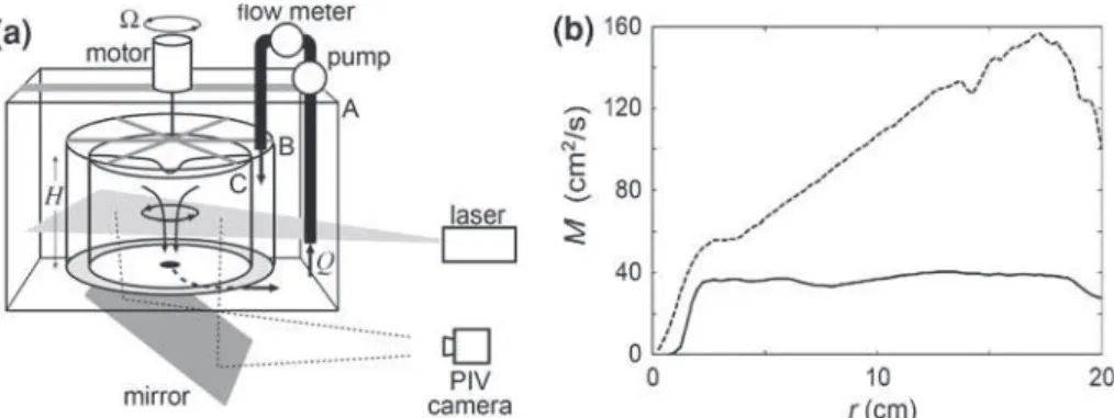
The schematic of the experimental set-up is shown in Fig.1a. A bathtub vortex is generated in a cylindrical tank of 40 cm diameter which rotates about its vertical central axis at a constant angular velocity . The working fluid, fresh water, is drained at a volume flux Q through a circular hole of 2.5 cm diameter at the bottom center, and the same amount of water is returned to the tank through its sidewall the upper part of which is made of sponge. The mean water depth of the tank is 18 cm. Horizontal velocity field measurements presented here were made at z =10 cm via a PIV technique.
Figure1b shows the radial distributions of angular momentum which demonstrates that two regimes of vortices are realized in the experiment: when Q is large and is small (solid line), the angular momentum (defined in the non-rotating frame) in the steady state is constant outside the vortex core (Regime I); when
Q is small or is large (dashed line), on the other hand, the angular momentum decreases with decreasing radius (Regime II). For Regime II, a flow visualization in the radial-vertical plane shows that a dye introduced near the top of the sidewall travels along the sidewall, goes into the boundary layer, moves radially inward and goes out of the drain hole (discussed in [12]).
3 Numerical experiment
The axisymmetric numerical model in cylindrical coordinates which is used in the present study consists of two prognostic equations for the vorticity in the r –z plane and angular momentum per unit mass M(r ) = vr. Here, r and z are the radial and vertical coordinates, respectively, v is the tangential velocity and the vorticity is expressed in terms of the stream function in the r –z plane through the continuity equation. Finite difference and leap-frog schemes are used to solve the equations. The boundary conditions are stress free at the central
Fig. 1 aSchematic of the experimental apparatus and b measured radial profiles of the angular momentum per unit mass M = vr for = 0.1 rad/s and Q = 100 cm3/s (solid line), and = 0.4 rad/s and Q = 33 cm3/s (dashed line)
20 10 0 20 10 0 40 20 0 160 80 0 0 10 20 0 10 20 (c) (a) (d) (b) r (cm) M (cm 2/s) z (cm) r (cm)
Fig. 2The streamlines in the r –z plane (a and c) and radial profiles of angular momentum per unit mass at the mid-depth (b and
d) as obtained from the numerical experiment. For a and b, = 0.1 rad/s and Q = 100 cm3/s, and for c and d, = 0.4 rad/s and Q = 33 cm3/s. The vertical thick line on the right side of the sidewall in a and c denotes the inflow region, and the thick
horizontal linebelow the horizontal axis in each panel the drain hole
axis, free slip at the upper lid and no slip at the bottom and sidewall which are rotating at the angular velocity . Note that the deformation of the free surface was neglected for simplicity. The drain hole occupies the central one-eighth radius of the bottom, and the inflow region the upper one-quarter of the sidewall.
The calculation is started from an initial state in which the whole system is in a solid-body rotation of angular velocity , the vorticity in the r –z plane is zero and the volume flux from the sidewall and through the drain hole is Q. It takes about 30-60 min to attain a steady state depending on the values of the external parameters and Q. For various combinations of and Q, time evolutions of the angular velocity in the laboratory experiment are well reproduced by the corresponding numerical experiment (see [13]). Figure2a, b shows streamlines in the r –z plane and radial profiles of angular momentum in the steady state at the height of 10 cm from the bottom, respectively, for Regime I, and Fig.2c, d those for Regime II. A comparison between Figs.1b and2b, d shows that the numerical experiment well reproduces the steady-state radial distribution of the angular momentum in the laboratory experiment. For Regime I, a majority of streamlines that start from the sidewall reaches the outer rim of the vortex core through the interior: this indicates that a non-zero radial flux towards the vortex core exists everywhere in the interior flow, transporting circulation from the external rotating wall and leading to an angular momentum distribution constant with radius (Fig.2b). By contrast, for Regime II, all of the streamlines go into the bottom boundary layer (Fig.2c) for r > 14 cm, and no radial flow is maintained in the interior for r < 14 cm, yielding an angular momentum that decreases with decreasing radius for r < 14 cm (see Fig.2d). It is worth noting that when the bottom boundary condition is artificially changed to free-slip, the angular momentum outside the vortex core becomes radially constant for the two regimes, demonstrating the leading role of the bottom boundary layer in generating non-constant angular momentum profiles.
4 Boundary layer theory
Since the numerical experiment has shown that the structure of the vortex is governed by the bottom boundary layer, the characteristics of the bottom boundary layer under a potential vortex is studied by a boundary layer theory. The structure of the boundary layer below a potential vortex was studied by Burggraf et al. [8], but the radial flux through the boundary layer, which is important in the present problem, was not reported. Here, the axisymmetric boundary layer equations (see [13]) were integrated with time to obtain a steady-state solution, with the side and bottom boundaries rotating at the angular velocity , the inner boundary chosen open, and the horizontal velocity components approaching those of the potential vortex at the upper boundary.
The boundary layer structure thus obtained coincides well with the one obtained for Regime I in the numer-ical experiment (see [13]). The radial volume flux through the bottom boundary layer scales as 2π R2(ν)12,
and depends on a non-dimensional function F (r ) that increases monotonously with decreasing radius (Fig.3). Here, R is the inner radius of the tank, ν the kinematic viscosity and r the non-dimensional radial coordinate. The maximum radial volume flux Qbmax through the bottom boundary layer is attained at the radius of the
drain hole, and is given by Qbmax= 0.88 × 2π R2(ν)
1
0 0.2 0.4 0.6 0.8 1.0 0 0.2 0.4 0.6 0.8 1.0 0.88 0.125 r F (r )
Fig. 3 Non-dimensional radial volume flux F (r ) through the bottom boundary layer. The thick solid curve shows the one obtained from the boundary-layer equation, and the dashed curve that obtained from the numerical experiment in Sect.3. The thin vertical linedenotes the non-dimensional radius of the drain hole (0.125) and the thin horizontal line the corresponding non-dimensional radial volume flux (0.88)
0 20 40 60 80 100 120 0 0.1 0.2 0.3 0.4 0.5 1.00 0.98 0.73 0.98 0.87 0.57 0.44 Ω (rad/s) Q (cm 3/s)
Fig. 4 The angular momentum at r = 4 cm scaled by that at the sidewall on the − Q plane as obtained from the numerical experiment. The solid curve shows the criterion given by Eq. (1)
Thus, since a potential vortex forms only when a non-zero radial flux exists in the whole interior, the radial volume flux in the boundary layer must remain everywhere smaller than the volume flux Q prescribed at the drain hole. As a consequence, a simple criterion for the realization of a potential vortex might be given by
Q >0.88 × 2π R2(ν)12 = 0.88 × 2π R · R ·
!ν
"12
(1) In Fig.4, results from numerical experiments are plotted in the − Q parameter plane, along with a solid line corresponding to the criterion (1) proposed above. As shown in the figure, potential vortices (those with an angular momentum at r = 4 cm roughly equal to the angular momentum prescribed by the external wall rotation) form only when (1) is satisfied. This criterion also nicely explains the results of the laboratory experiments (see [13]).
5 Summary and conclusions
The mechanism through which the radial distribution of the tangential velocity in a bathtub vortex is deter-mined is studied by means of laboratory and numerical experiments and a boundary layer theory. Two different regimes of the vortex are found to exist : In the first regime (Regime I), a potential vortex in which the angular momentum is constant outside the vortex core is found both experimentally and numerically. In the second regime (Regime II), on the other hand, the angular momentum decreases with decreasing radius. Which regime occurs depends on the relative magnitudes of the volume flux Q and the maximum value Qbmaxof the radial
volume flux Qbin the boundary layer below a potential vortex. When Q > Qbmax, Regime I is realized, while
The present study clearly shows that the radial distribution of the tangential velocity in a bathtub vortex is strongly controlled by the bottom boundary layer. It has often been assumed that the radial distribution of the tangential velocity in strong vortices in nature and in engineering flows in a container is approximated by that of a Rankine vortex. However, the present study demonstrates that the angular momentum outside the vortex core is not necessarily constant. These results may give some insight in the recent observation by Wurman and Gill [1] of the velocity distribution in violent atmospheric vortices.
The present paper summarizes the essence of the first author’s doctor thesis [13]. More detailed results will be soon reported elsewhere.
References
1. Wurman, J., Gill, S.: Finescale radar observations of the Dimmitt, Texas (2 June 1995), Tornado. Mon. Wea. Rev. 128, 2135– 2164 (2000)
2. Lewellen, W.S.: A solution for three-dimensional vortex flows with strong circulation. J. Fluid Mech. 14, 420–432 (1962) 3. Turner, J.S.: The constraints imposed on tornado-like vortices by the top and bottom boundary conditions. J. Fluid Mech.
25, 377–400 (1966)
4. Lundgren, J.: The vortical flow above the drain-hole in a rotating vessel. J. Fluid Mech. 155, 381–412 (1985) 5. Mory, M., Yurichenko, N.: Vortex generation by suction in a rotating tank. Eur. J. Mech. B/Fluids 12, 729–747 (1993) 6. Echavez, G., McCann, E.: An experimental study on the free surface vertical vortex. Exp. Fluids 33, 414–421 (2002) 7. Andersen, A., Bohr, T., Stenum, B., Rasmussen, J.J., Lautrup, B.: The bathtub vortex in a rotating container. J. Fluid Mech.
556, 121–146 (2006)
8. Burggraf, O.R., Stewartson, K., Belcher, R.: Boundary layer induced by a potential vortex. Phys. Fluids. 14, 1821–1833 (1971)
9. Andersen, A.T., Lautrup, B., Bohr, T.: An averaging method for nonlinear laminar Ekman layers. J. Fluid Mech. 487, 81–90 (2003)
10. Jacquin, L., Fabre, D., Geffroy, P., Coustols, E.: The properties of a transport aircraft wake in the extended near field—an experimental study. In: Proceedings of the AIAA, Aerospace Sciences Meeting and Exhibit, 39th, Reno (2001)
11. Jacquin, L., Fabre, D., Sipp, D., Coustols, E.: Unsteadiness, instability and turbulence in trailing vortices—comptes rendus-Physique (2005)
12. Noguchi, T., Yukimoto, S., Kimura, R., Niino, H.: Structure and instability of a sink vortex. In: Proceedings of PSFVIP-4 (2003)
13. Yukimoto, S.: Structure of a Suction Vortex: Importance of the Bottom Boundary Layer. Doctoral Dissertation, Dep. Earth Planet. Sci., The University of Tokyo, 77 p. (2008)