SEYED ALIREZA ZABIHIAN
DÉPARTEMENT DE GÉNIE ÉLECTRIQUE ÉCOLE POLYTECHNIQUE DE MONTRÉAL
MÉMOIRE PRÉSENTÉ EN VUE DE L’OBTENTION DU DIPLÔME DE MAÎTRISE ÈS SCIENCES APPLIQUÉES
(GÉNIE ÉLECTRIQUE) DÉCEMBRE 2017
UNIVERSITÉ DE MONTRÉAL
ÉCOLE POLYTECHNIQUE DE MONTRÉAL
Ce mémoire intitulé:
TOWARDS BRAIN AREA SENSOR WIRELESS NETWORK
présenté par :
en vue de l’obtention du diplôme de : ZABIHIAN Seyed Alireza
a été dûment accepté par le jury d’examen constitué de :
Maîtrise ès Sciences Appliquées
M. SAVARIA Yvon M.
, Ph. D., président SAWAN Mohamad
M.
, Ph. D., membre et directeur de recherche NABKI Frédéric
M.
, Ph. D., membre et codirecteur de recherche COHEN-ADAD Julien, Ph. D., membre
ACKNOWLEDGEMENTS
I would like to express my sincere gratitude to my research director Prof. Mohamad Sawan that gave me the opportunity to pursue my researches in Polystim Neurotechnologies Laboratory and LASEM, and all the technical and general supports in these few years at Polytechnique Montreal. Also, especial thanks to my co-supervisor Prof. Nabki for technical discussions particularly on RF transceiver design in his RF Microelectronics class at McGill University. I appreciate Prof. Savaria and Prof. Cohen-Adad kindly accepting to evaluate this thesis.
I am grateful to all the staff of Electrical Engineering Department of Polytechnique Montreal, specially Marie-Yannick Laplante, Laurent Mouden, Jean Bouchard, and, Réjean Lepage for all their help.
I would also like to thanks my colleagues and friends at Polystim for useful discussions and help, especially Saeid Hashemi, Md. Hasanuzzaman, Sami Hached, Omar Al-Terkawi Hasib, Sreenil Saha, Mohamed Zgaren, Ehsan Kamrani, Ahmad Hassan, Moez Bouali, and, P.A. Sauriol.
I would like to acknowledge Natural Sciences and Engineering Research Council of Canada (NSERC), the Canada Research Chair in Smart Medical Devices, and Regroupement Stratégique en Microsystèmes du Québec (ReSMiQ) for the support and Canadian Microelectronics Corporation (CMC) Microsystems for the design and simulation tools.
And last, but the most important of all, thanks God for giving me peace of heart and mind when I prayed in the hard moments I had here far away from my family. I am and will always be grateful of my kind parents for their unconditional love and support.
l'électrocorticographie (ECoG) et les méthodes d'interfaçage intracortical conventionnelles à une seule unité, offre de meilleures caractéristiques pour implémenter des IMC plus performants. Les avantages de la nouvelle approche sont 1) une résolution spatiale plus élevée - en dessous du-millimètre, et une qualité de signal plus élevée - en termes de rapport signal sur bruit et de contenu fréquentiel - comparé aux méthodes EEG et ECoG; 2) un caractère moins invasif que l'ECoG où l'enlèvement du crâne sous une opération d'enregistrement / stimulation est nécessaire; 3) une plus grande faisabilité de la libre circulation du patient à l'étude - par rapport aux deux méthodes EEG et ECoG où de nombreux fils sont connectés au patient en cours d'opération; 4) une utilisation à long terme puisque l'interface implantable est sans fil - par rapport aux deux méthodes EEG et ECoG qui offrent des temps limités de fonctionnement.
Nous présentons l'architecture d'un réseau sans fil de microsystèmes implantables, que nous appelons Brain Area Sensor NETwork (Brain-ASNET). Il y a deux défis principaux dans la réalisation du projet Brain-ASNET. 1) la conception et la mise en œuvre d'un émetteur-récepteur RF de faible consommation compatible avec la puce de capteurs de réseau implantable, et, 2) la conception d'un protocole de réseau de capteurs sans fil (WSN) ad-hoc économe en énergie. Dans ce mémoire, nous présentons un protocole de réseau ad-hoc économe en énergie pour le réseau désiré, ainsi qu'un procédé pour surmonter le problème de la longueur de paquet variable causé par le processus de remplissage de bit dans le protocole HDLC standard. Le protocole ad-hoc proposé conçu pour Brain-ASNET présente une meilleure efficacité énergétique par rapport aux protocoles standards tels que ZigBee, Bluetooth et Wi-Fi ainsi que des protocoles ad-hoc de pointe. Le protocole a été conçu et testé par MATLAB et Simulink.
A partir de la conception du système Brain-ASNET, nous avons choisi la modulation On-Off Keying (OOK) sur une bande de fréquence industrielle, scientifique et médicale (ISM) de
902-928 MHz comme la meilleure option pour nos exigences d'application. Ayant fait des recherches sur des conceptions d'architecture d'émetteur-récepteur RF ULP de pointe, nous sommes venus avec une nouvelle idée pour la conception de l'architecture de transmetteur RF ULP OOK. L'architecture proposée utilise un oscillateur à anneau multi-phase à verrouillage par injection multi-phase OOK qui, comparé aux émetteurs RF ULP de pointe, fournit un débit de données élevé (plage de 10 Mbits / s) avec un rendement énergétique élevé, tout en consommant une petite aire de silicium.
Pour mettre en œuvre l'idée de Brain-ASNET, l'architecture et la conception entièrement personnalisée d'un système sur puce (SoP) à très faible consommation d'énergie (ULP) sont également présentées. Le frontal analogique (AFE) du SoC utilise un ADP (Analogique-Numérique) ULP à 8 bits conçu et mis en place sur mesure. Le SoC est conçu pour être configurable en tant que puce de nœud de capteur ou en tant que module RF frontal dédié du coordinateur et contrôleur de réseau correspondant. Le SoC est conçu et mis en place, en utilisant les outils de conception de circuits intégrés de Cadence, en exploitant un procédé CMOS de 0.13μm d'IBM. Sa superficie sur silicium est de 1.4 par 1.4 mm2. Les résultats de simulation post-implantation montrent une bonne efficacité énergétique du protocole de réseau ad-hoc conçu et une faible dissipation de puissance du SoC, en particulier l'émetteur RF ULP proposé. La puce entière,ycompristouslescomposants intégrés fonctionnels et périphériques, consomme 138μW et 412μW, à 1,2V, configurés dans un réseau synchronisé en tant que nœud de capteur et coordinateur respectivement. L'émetteur ULP OOK RF proposé a une puissance de sortie de 22 dBm qui est en dessous de la limite de puissance ISM. Il dissipe 137μW de puissance à un débit de 2,75Mbps lorsque la tension d'alimentation est de 1,2V. Compte tenu du fonctionnement programmé de chaque nœud de capteur synchronisé, la dissipation de puissance moyenne de l'émetteur du nœud de capteur est aussi faible que 28μW.
Le matériel électronique du coordonnateur et un logiciel d'interface utilisateur en langage Python ont été construits avec l'aide d'un stagiaire de premier cycle. La plate-forme a été testée avec succès avec différents signaux de test. La puce fabriquée a été mesurée et son émetteur RF ainsi que son récepteur ont été testés séparément. Cependant, étant donné que la puce fabriquée n'était pas entièrement fonctionnelle, nous n'avons pas pu la tester en tant que capteur dans un Brain-ASNET en liaison avec le coordinateur et la plate-forme de commande.
interfacing methods offers better features to implement higher-performance BMIs. The new approach advantages are 1) higher spatial resolution – down to sub-millimeter, and higher signal quality − in terms of signal-to-noise ratio and frequency content − compared to both EEG and ECoG methods. 2) being less invasive than ECoG where skull removal under recording/stimulation surgery is required. 3) higher feasibility of freely movement of patient under study − compared to both EEG and ECoG methods where lots of wires are connected to the patient under operation. 4) long-term usage as the implantable interface is wireless − compared to both EEG and ECoG methods where it is practical for only a limited time under operation.
We present the architecture of a wireless network of implantable microsystems, which we call it Brain Area Sensor NETwork (Brain-ASNET). There are two main challenges in realization of the proposed Brain-ASNET. 1) design and implementation of power-hungry RF transceiver of the implantable network sensors' chip, and, 2) design of an energy-efficient ad-hoc Wireless Sensor Network (WSN) protocol.
In this thesis, we introduce an energy-efficient ad-hoc network protocol for the desired network, along with a method to overcome the issue of variable packet length caused by bit stuffing process in standard HDLC protocol. The proposed ad-hoc protocol designed for Brain-ASNET shows better energy-efficiency compared to standard protocols like ZigBee, Bluetooth, and Wi-Fi as well as state-of-the-art ad-hoc protocols. The protocol was designed and tested by MATLAB and Simulink.
From the Brain-ASNET system design we choose On-Off Keying (OOK) modulation on an Industrial, Scientific and Medical (ISM) frequency band of 902−928MHz as the best option for our application requirements. Having done research on state-of-the-art ULP RF transceiver
architecture designs, we came with a new idea for ULP OOK RF transmitter architecture design. The proposed architecture employs an OOK multi-stage multi-phase injection-locked ring oscillator which compared to its state-of-the-art ULP RF transmitter designs provides high data rate (10-Mbps range) at a high power efficiency, at a small silicon area.
To implement the Brain-ASNET idea, architecture and full-custom design of an Ultra-Low Power (ULP) System-on-Chip (SoC) is also presented. The SoC's Analog Front-End (AFE) utilizes a full-custom designed and laid-out ULP 8-bit Success-Approximation Analog-to-Digital (ADC). The SoC is designed to be configurable as either a sensor node chip or the network coordinator’s dedicated RF front-end and corresponding network controller. The SoC is designed and laid-out, using Cadence IC Tools, in an IBM 0.13µm CMOS process, with a silicon area of 1.4 by 1.4 mm2. The post-layout simulation results show good energy efficiency of the designed ad-hoc network protocol and low power dissipation of the SoC, particularly the proposed ULP RF transmitter. The whole chip, including all functional and peripheral integrated components, consumes 138µW and 412µW, at 1.2V, configured in a synchronized network as a sensor node and the coordinator, respectively. The proposed ULP OOK RF transmitter has an output transmit power of –22dBm – below the ISM power limit, and dissipates 137µW of power at a date rate of 2.75Mbps at 1.2V supply voltage. Considering the scheduled operation of each synchronized sensor node, the average power dissipation of the sensor node’s transmitter is as low as 28µW. The coordinator's electronics hardware and a computer user interface software using Python language are constructed with assistance of an undergraduate intern. The platform was tested successfully with different test signals. The fabricated chip was measured and its RF transmitter and receiver were separately tested. However, because the fabricated chip was not whole functional, we could not tested it as Brain-ASNET sensors in connection with the coordinator and GUI platform.
LIST OF SYMBOLS AND ABBREVIATIONS ... XV LIST OF APPENDICES ... XIX
CHAPTER 1 INTRODUCTION ... 1
1.1 Project Overview ... 1
1.1.1 Energy-Efficient WSN Protocols ... 2
1.1.2 Low-Power Intracortical Neural Recording SoC Design ... 2
1.1.3 Ultra-Low Power Low-Voltage RF Transmitters ... 3
1.1.4 Project Organization ... 4
1.2 Motivation ... 5
1.3 Basic Principles of Neural Recording Methods ... 5
1.4 Research Objectives and Challenges ... 12
1.5 Contributions ... 13
1.6 Thesis Outline ... 14
CHAPTER 2 PROPOSED GENERAL IDEA, AND, LITERATURE REVIEW ... 15
2.1 Proposed General Idea: Brain Area Sensor Network ... 15
2.1.1 Potential Developments and Applications ... 18
CHAPTER 3 ARCHITECTURE, SYSTEM AND CIRCUIT DESIGNS ... 31
3.1 Brain-ASNET Design and Implementation Aspects ... 31
3.1.1 Sensor Node Design and Implementation ... 32
3.1.2 Coordinator Design and Implementation ... 37
3.1.3 User Interface Design and Implementation ... 38
3.2 Ad-hoc Protocol Design for Brain-ASNET ... 40
3.3 ULP RF Transmitter Design for Brain-ASNET ... 48
CHAPTER 4 CHIP LAYOUT, SIMULATION AND MEASUREMENT RESULTS ... 52
4.1 Circuit and Layout Designs, and, Simulation Results ... 52
4.2 Implementation and Measurement Results ... 59
CHAPTER 5 CONCLUSIONS AND FUTURE WORK ... 63
5.1 Summary and Discussion ... 63
5.2 Directions for Future Work ... 64
REFERENCES ... 67
Table 3.2: Brain-ASNET vs. Traditional ad-hoc WSNs and BSNs ... 40
Table 3.3: Protocol design features of Brain-ASNET vs. traditional WSNs and BSNs ... 45
Table 3.4: The standard HDLC vs. the proposed modified HDLC protocols ... 45
Table 4.1: Optimized transistor sizing of the designed OOK RF transmitter ... 54
Table 4.2: Performance summery of the proposed ULP RF transmitter vs. state-of-the-art ... 54
Table 4.3: Performance summery of the designed SoC for Brain-ASNET ASIC ... 57
LIST OF FIGURES
Figure 1.1: Typical architecture of wireless intracortical neural recording sensors ... 3
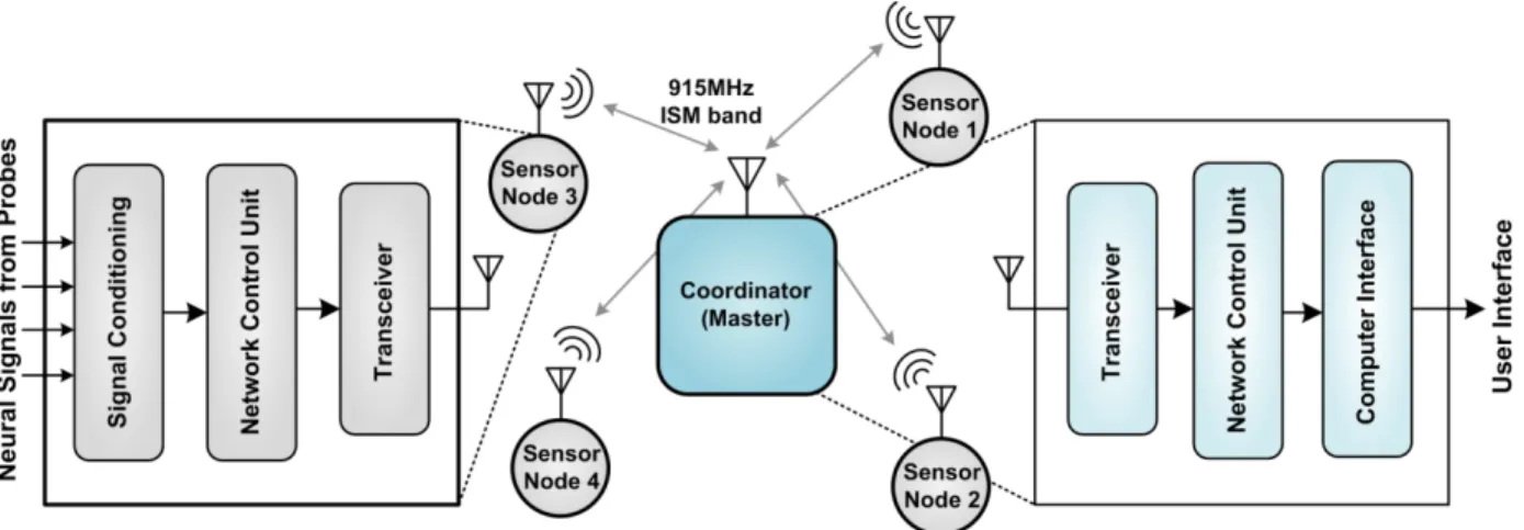
Figure 1.2: The simplified Brain-ASNET, sensor node, and coordinator architectures ... 4
Figure 1.3: The sensory and motor regions discovered on the human cerebral cortex [8] ... 6
Figure 1.5: The Meninges of the central nerves system [8] ... 8
Figure 1.4: A high-density EEG recording with epileptic spikes and wave discharges ... 8
Figure 1.6: ECoG: surface subdural electrodes cover an exposed area of cerebral cortex [14] ... 9
Figure 1.7: Electrophysiological methods to electrically interface with the brain [8] ... 10
Figure 1.8: A neural microsystem consisting of 2-D and 3-D microelectrode arrays [16] ... 11
Figure 1.9: A illustration of BCI using wireless single-unit neural recording implants [17] ... 11
Figure 2.1: An illustration of the proposed Brain-ASNET ... 17
Figure 2.2: Recording-Only Centralized Brain-ASNET ... 19
Figure 2.3: Recording-and-Simulation Centralized Brain-ASNET ... 19
Figure 2.4: Recording-and-Simulation Distributed Brain-ASNET ... 20
Figure 2.5: Main data network topologies [33] ... 21
Figure 2.6: The main digital modulation schemes ... 23
Figure 2.7: A wireless BSN, connected to a local server and the internet [2] ... 28
Figure 2.8: Omeni-Toumazou's protocol: a) Clustered topology, b) Link establishment [3] ... 30
Figure 3.1: General space of design and implementation aspects of Brain-ASNET ... 31
Figure 3.2: The designed sensor-coordinator Brain-ASNET ASIC architecture ... 32
Figure 3.3: General AFE architecture of multi-channel neural recording systems [4] ... 33
Figure 3.4: A neural-recording AFE architecture with one conventional ADC per channel [47] . 34 Figure 3.5: A neural-recording AFE architecture with one ∆Σ modulator per channel [48] ... 34
Figure 3.13: The network protocol dedicated design for Brain-ASNET: a) time frame and slots,
b) beacon frame structure, and, c) sensor-specific frame structure ... 44
Figure 3.14: NCU logic design a) Master-Slave Packetizer, and b) Master-Slave Depacketizer .. 46
Figure 3.15: The simplified architecture of the proposed ULP OOK RF transmitter ... 48
Figure 3.16: Proposed OOK RF TX: a) two-stage multi-phase ILRO, and, b) EC-PA ... 50
Figure 3.17: The combination of edge pulses, modulated with TXIN ... 51
Figure 3.18: The ULP OOK RF receiver architecture designed for the Brain-ASNET ASIC ... 51
Figure 4.1: The proposed ULP OOK RF transmitter: a) Hierarchical design schematic, b) design schematic of the TX Component, and, c) design schematic of the TX EC NAND3C ... 53
Figure 4.2: Layout design of the proposed ULP OOK RF transmitter ... 53
Figure 4.3: Power spectrum of OOK RF transmitter output: a) free-running, b) injection-locked 54 Figure 4.4: Monte-Carlo simulations: a) variations in RO2 free-running osc. freq., b) histogram 55 Figure 4.5: Layout design of the ULP OOK RF receiver ... 55
Figure 4.6: Post-layout simulation results of a sensor node’s OOK RF transmitter input and antenna output, and the coordinator's OOK RF receiver output, respectively ... 56
Figure 4.7: Designed Brain-ASNET ASIC: a) chip layout, and b) power consumption chart ... 56
Figure 4.8: Post-layout simulation results of one selected channel of each of four sensor nodes . 57 Figure 4.9: Layout design of the ULP 8-bit SAR ADC ... 58 Figure 4.10: Power requirements of this work vs IEEE standards and Omeni-Toumazou's work 59
Figure 4.11: A micrograph of the fabricated Brain-ASNET ASIC ... 59 Figure 4.12: Simplified test bench setups used for Brain-ASNET sensor node measurements .... 60 Figure 4.13: A Brain-ASNET sensor node module implemented using the fabricated ASIC ... 60
ALOHA Additive Links On-line Hawaii Area AM Amplitude Modulation
AP Action Potential
ARQ Automatic Repeat Request
ASIC Application-Specific Integrated Circuit BCI Brain-Computer Interface
BER Bit Error Rate
BMI Brain-Machine Interface
Brain-ASNET Brain Area Sensor NETwork BSN Body Sensor Network
CDMA Code Division Multiple Access
CMOS Complementary Metal–Oxide–Semiconductor CNS Central Nervous System
CRC Cyclic Redundancy Check CSF Cerebrospinal Fluid
CSMA Carrier-Sense Multiple Access DAC Digital-to-Analog Converter DLL Data-Link Layer
DLL Delay-Locked Loop ECC Error-Correcting Code ECoG Electrocorticography
EC-PA Edge-Combining Power Amplifier EEG Electroencephalography
ENOB Effective-Number-of-Bits ESD Electrostatic Discharge FCS Frame Check Sequence
FDM Frequency-Division Multiplexing FDMA Frequency Division Multiple Access FEC Forward Error Correction
FM Frequency Modulation FSK Frequency Shift-Keying
FTSP Flooding Time Synchronization Protocol GUI Graphic User Interface
HARQ Hybrid Automatic Repeat-Request HDLC High-level Data Link Control
IBM International Business Machines Corporation IC Integrated Circuit
iEEG intracranial Electroencephalography ILRO Injection-Locked Ring-Oscillator ISM Industrial, Scientific, Medical LC Inductor-Capacitor
LV Low-Voltage
MAC Media Access Control
MACAW Multiple Access with Collision Avoidance for Wireless MICS Medical Implant Communication Service
MOSIS Metal Oxide Semiconductor Implementation Service MRI Magnetic Resonance Imaging
MUX Multiplexer
NCU Network Control Unit OOK On-Off Keying
OSI Open Systems Interconnection PC Personal Computer
PCB Printed Circuit Board PHY Physical
PLL Phase-Locked Loop PM Phase Modulation POR Power On Reset QFN Quad Flat No-leads
RF Radio Frequency RMS Root Mean Square RO Ring Oscillator
RX Receiver
SAR Specific Absorption Rate
SAR ADC Successive-Approximation Register Analog-to-Digital Convertor
SN Sensor Node
SNDR Signal-to-Noise Ratio SoC System-on-Chip SYNC Synchronization
TDM Time-Division Multiplexing TDMA Time Division Multiple Access TDP Time-Diffusion Synchronization
TPSN Timing-sync Protocol for Sensor Networks TRAMA Traffic-Adaptive Medium Access
TRX Transceiver
TX Transmitter
UHF Ultra-High Frequency ULP Ultra-Low Power UWB Ultra Wide-Band
WLAN Wireless Local Area Network WPAN Wireless Personal Area Network WSN Wireless Sensor Network
CHAPTER 1
INTRODUCTION
There are numerous researches currently being done around the world to improve the human quality of life, and particularly those with disabilities. Recording neural signals from the nervous system and body tissues and also ability to stimulate the central nervous system and nerves have made it possible to build different Brain-Machine Interfaces (BMIs) to be utilized as assistive devices for disabled and/or to study and understand living beings nervous systems.
1.1 Project Overview
Our research project aimed at building a new wireless intracortical neural recording system. As part of this work, we performed analysis, design, and implementation of implantable neural recording sensors and of a wireless coordinator that exploits a proposed low-power networking protocol. The overall project objectives were to design and implement ultra-low power application-specific System-on-Chip (SoC), validating the proposed platform based on a wireless network of SoCs comprising multiple sensors, and a coordinator. Meanwhile we came with a couple of ideas to make an energy-efficient Wireless Sensor Network (WSN). As a result, we introduce an ad-hoc network protocol, that we call a modified-HDLC, which solves some common issues with the standard HDLC protocol. The proposed ad-hoc protocol is way more energy-efficient than WSN standard protocols such as ZigBee, Bluetooth, and Wi-Fi and even other highly-cited state-of-the-art ad-hoc protocols. Finally, we talk about our proposed ultra-low power RF OOK transmitter architecture that shows significant improvements over state-of-the-art designs in terms of data rate, power efficiency, etc.
Different methods are used to record neural activities of body tissues and nervous system. Between them, Electroencephalography (EEG), Electrocorticography (ECoG), and, Intracortical Neural Recording are the most conventional methods to record neural activities as electrical signals. Each of these three methods have their own pros and cons. This thesis introduces a novel method that merge and utilized advantages of these three methods, as it will be described later in the current and next chapters. We build a wireless network of multi-channel intracortical neural recording implants that facilitates having wireless intracortical neural recording of the brain over many channels. It makes possible to have a high-spatial resolution recording interface, while it reduces any chance of infection for chronic use and it also makes patient's movement free,
show the majority of application-specific wireless sensor networks, such as Body Sensor Networks (BSN) use their own-defined protocol set to minimize the energy loss where usually standard protocols such as Bluetooth and Wi-Fi are better when a general-purpose programmable BSN sensor module is designed for public market. Researchers have been introducing novel application-specific networking MAC protocols for wireless BSNs in the last few decades, both contention-based and contention-free, from time- and frequency- to code- division multiple access such as TRAMA, Y-MAC, DESYNC-TDMA, LEACH, and, LMAC [1]. Between them, TDMA protocols are the most popular ones for limited centralized networks like BSNs [2]. Since we had an application-specific network (Brain-ASNET) to implement, we researched on protocol design and proposed an energy-efficient ad-hoc network protocol, called modified HDLC, that solves common issues with HDLC standard protocol, and it leads to less implementation complexity and lower power consumption compared to flexible standard protocols as well as state-of-the-art ad-hoc protocols like a highly-cited ad-hoc WSN protocol proposed by Omeni-Toumazou [3]. This will be described in more details in the chapters 2 and 3.
1.1.2 Low-Power Intracortical Neural Recording SoC Design
The design and implementation of a wireless intracortical implant, capable of multi-channel recording from the brain cortex, is a huge multidisciplinary job that requires wide knowledge including nervous system and body tissue biological characteristics, microelectrode fabrication, body-electrode interface characterises, Analog, Mixed-mode, Digital, and, RF integrate circuit and system design and fabrication, data networking and wireless communication, antenna design, and many more. In this project we studied on different state-of-the-art architectures for intracortical-recording implants with focus on ultra-low-power low-voltage SoC design and
implementation. Figure 1.1 shows a typical wireless intracortical neural recording sensor. There have been numerous researches done (and still in progress) on power-efficient and silicon-area-efficient design of each of the main functional building blocks. Studies show Analog Front-End (AFE) architecture design can be optimized based on the number of recording channels [4]. Successive-Approximation Register (SAR) Analog-to-Digital Convertor (ADC) architecture is one of the best candidates for ultra-low-power AFE design. In this project we focused on the ADC and digital controller designs to minimize the power and silicon area for a preliminary four-channel neural recording sensor. However, as many researches indicate the main power-hungry building block of such wireless microsystems is their wireless RF transceiver, even for short-range communication that is required for limited-size WSNs like BSNs.
1.1.3 Ultra-Low Power Low-Voltage RF Transmitters
Considering that RF transceiver is the main power-consuming building block of an wireless intra-cortical neural recording implant's SoC, it is crucial to employ the most state-of-the-art energy-efficient RF transceiver architecture. In this project, different design aspects of the physical layer for the Brain-ASNET, between the implant sensors and the coordinator, were studied. Therefore, On-Off Keying (OOK) modulation on an Industrial, Scientific and Medical (ISM) frequency band of 902-928MHz was chosen as the best option for our application requirements. We came with a new idea to design a highly energy-efficient OOK RF transmitter for a Mbps-range data
Amplifier
& Filter Converter A/D Neural Signal Processor Transceiver Control Unit
Power Supply Unit
rate compared to the state-of-the-art. This architecture employs an OOK multi-stage multi-phase injection-locked ring oscillator which compared to its FSK counterpart is capable of having few tens of times higher data rate (around 20 Mbps). We talk about this proposed architecture, and its chip circuit and layout designs for our application, in the chapter 3.
1.1.4 Project Organization
A successful architecture-, system- and circuit- level design and implementation of the Brain-ASNET requires adoption of the best design options and post analyses to build a robust implementation. There are many tasks to design and implement whole Brain-ASNET system so that it is functional and ready for operation and experiment. As it will be described in details later in chapter 3, for this Master's project, we consider a wireless network consisting of the coordinator and four intracortical neural recording sensors, each sensor with four neural recording input channels. Figure 1.2 shows the simplified network architecture of this Brain-ASNET, including the master coordinator and four slave sensor node simplified architectures. Because of the multidisciplinary nature of design and implementation of Brain-ASNET, many design tasks are required to be done, including the main ones listed below:
Task 1: Network architecture and topology
Task 2: Network DLL, MAC, and, PHY protocol layers Task 3: Sensor's architecture, system and circuit
3.1: Microelectrode arrays
3.2: Multi-channel analog front-end (including neural amplifiers, ADCs, and, MUXs) 3.3: Digital internal and network protocol controllers (control unit)
3.4: RF transceiver 3.5: Miniature antenna
Task 4: Coordinator and Computer User Interface
In this thesis we performed most of the tasks listed above, with detailed discussion on tasks 2 and 3.4 where we came with new ideas to design and implement the best energy-efficient ad-hoc network protocol and ULP RF transmitter for our specific application, an initial version of a centralized Brain-ASNET.
1.2 Motivation
BMIs demand for high-performance recording/stimulation capabilities in terms of speed, quality, and quantity, i.e. higher frequency bandwidth, spatial resolution, signal-to-noise ratio, and wider area to interface with the cerebral cortex. In this thesis, we talk about the general idea of a novel neural interfacing method which in comparison with EEG, ECoG and conventional single-unit neural interfacing methods offers better capabilities to implement higher-performance BMIs. As the two main challenges in realization of the Brain-ASNET are design and implementation of the power-hungry RF transceiver and WSN protocol, we discuss about our ideas on design of an ULP RF OOK transmitter and an energy-efficient ad-hoc network protocol.
1.3 Basic Principles of Neural Recording Methods
Nowadays, different sciences and engineering techniques are employed in new multi-disciplinary research fields such as biomedical engineering. Neural engineering has introduced Brain Machine Interfaces (BMI) as promising devices for assisting patients with cognitive or sensory-motor disabilities and/or neurological injuries. BMIs were initially introduced to the scientific literature in 1970s by researchers from University of California, Los Angeles (UCLA) [5]. They can be used to control electromechanical devices by processing neural signals recorded from the brain, or to stimulate special parts of the brain like vision and cochlear cortex by signals recorded from electronic devices which function similar to real sensory organs.
Because of the electro-chemical nature of neurons and neural systems, electrophysiological methods are the most conventional neural interfacing approaches for recording from and/or stimulation of the brain. For the first time, large-scale electrical neural recording from the brain based on Electroencephalography (EEG) was performed in 1924 [6]. While recorded EEG signals were not informative enough to study severe epilepsy, an invasive method called Electrocorticography (ECoG) was studied by neurosurgeons at the Montreal Neurological Institute in 1950s [7]. Later, Single-Unit Neural Interfacing was employed by researchers to study neural functions and structure of the brain at higher spatial and temporal resolutions. Current researches and available technologies to implement high-performance BMIs are still in their preliminary states.
Neuroscientists believe in the future they would be able to obtain a comprehensive knowledge about the whole structure and functions of the most complicated neural system, the human brain. Figure 1.3 shows the sensory and motor regions discovered on the human cerebral cortex. In fact, the brain is a complicated tissue made of neural cells. Electrochemical signals of the brain activities can be recorded and interpreted to recognize how its complex cellular network works. The specialized cells of the nerves system are called neurons, also known as nerve cells. They basically process and transmit information through chemical and electrical signals from one end to the other end of neuron. The electrochemical transmission across a neuron can described as
follows: 1) There are ion pumps combined with ion channels embedded in the neuron membrane. 2) Intracellular-to-extracellular concentration differences of ions (such as sodium, potassium, chloride, and calcium) can alter the function of voltage-dependent ion channels. 3) If this potential difference changes more than a specific amount, an electrochemical pulse called Action Potential (AP) is generated that causes the same scenario in adjacent ion channels and pump, and like a domino goes along the cell's axon. 4) In the end of neuron, the AP activates synaptic connections with other cells when it arrives [8].
Since research on understanding of functions and structure of the brain and neural system has been begun, different methods to analyze the brain activities have been introduced. These include Electroencephalography (EEG), Singe-Unit Recording & Stimulation, Electrocorticography (ECoG), Magnetic Resonance Imaging (MRI), functional Magnetic Resonance Imaging (fMRI), Computed Tomography (CT), Positron Emission Tomography (PET), Magnetoencephalography (MEG), Nuclear Magnetic Resonance Spectroscopy (NMRS), Single-Photon Emission Computed Tomography (SPECT), Near-InfraRed Spectroscopy (NIRS), and, functional Near-InfraRed Spectroscopy (fNIRS).
These methods can generally be categorized in two: electrophysiological versus neuroimaging techniques. Each of these methods has its own potential benefits. Since the nature of information transmitted between neurons is based on electrochemical signaling, it is more convenient to record neural signal and/or simulate neurons by electrophysiological interfaces. Here we talk about three most conventional electrophysiological neural interfacing methods, i.e. EEG, ECoG, and Single-Unit Neural Interfacing.
• Electroencephalography: By placing surface electrodes along the scalp, spontaneous
electrical activities of the brain are monitored (Figure 1.4). EEG is usually used for diagnostic applications, generally focusing on spectral content of neural oscillations, also known as brain waves. In the simplest way abnormalities in EEG readings can be diagnosed as epilepsy. However, to diagnose sleep disorders, coma, encephalopathy, and brain death, special diagnostic algorithms and spectral analyses are needed to interpret the results [9]. Some of the main issues of using EEG to diagnose brain activities include: 1) Low spatial resolution. For example, fMRI can directly display areas of the brain that are active, while EEG requires intense interpretation just to hypothesize what areas are activated by a
particular response [10]. 2) Poor signal-to-noise ratio. EEG measures Local Field Potentials (LFPs) which are results of neural activities of numerous neurons that occur in the cortex, layers below the scalp (Figure 1.5). This requires sophisticated data analysis and relatively large numbers of subjects to extract useful information from EEG. Nevertheless, because EEG is a non-invasive non-expensive electrophysiological monitoring method, it is still preferred over some invasive methods and different researches are being done to obtain better results from EEG.
• Electrocorticography: ECoG, also known as intracranial electroencephalography (iEEG), is a
type of electrophysiological interfacing with the cerebral cortex using subdural/epicortical surface electrodes placed directly on the exposed surface of the brain (Figure 1.6).
Figure 1.5: The Meninges of the central nerves system [8]
Considering the low conductivity of the skull bone (Figure 1.5), LFPs recorded by ECoG have higher quality than that of EEG. A typical adult human EEG signal is about 10μV to 100μV in amplitude when measured from the scalp, and is about 10–20mV when measured by subdural electrodes [11]. ECoG offers a temporal resolution of approximately 5ms and a spatial resolution of 1cm [12]. These LFPs, also known as synchronized postsynaptic potentials, primarily from cortical pyramidal cells, must be conducted through several layers of the cerebral cortex, cerebrospinal fluid (CSF), pia mater, and arachnoid mater before reaching subdural electrodes placed just below the dura mater.
This method requires an surgery to remove the skull that makes it a risky and extremely-invasive procedure, and not popular except for especial cases, like back in 1950s when neurosurgeons used this approach to study severe epilepsy. Recently, researches have introduced an alternative approach instead of invasive ECoG, where similar information can be obtained by integrating EEG and MRI methods [13]. Nevertheless, ECoG has its own benefits and one can follow recent advances on researches relevant to ECoG at International Workshop on Advances in Electrocorticography [14].
• Single-Unit Neural Interfacing: This method is to interface with single neurons using a
microelectrode system. In the simplest way, the tip of a microelectrode is inserted into a single neuron membrane or is placed adjacent to a single neuron or a population of neurons, so that it can record action potentials, intracellularly or extracellularly, respectively. The microelectrodes need to be fine-tipped, and high-impedance, that are mainly glass micro-
Figure 1.7: Electrophysiological methods to electrically interface with the brain [8] pipettes or metal microelectrodes [15]. This neural interfacing method is popular in cognitive science studies, where it permits the analysis of human cognition and cortical mapping. It has allowed researchers to discover the role of different parts of the brain in function and behavior. Single-unit neural interfacing is considered in two sub-categories of intracellular and extracellular. Figure 1.7 and Table 1.1 compare these three electrophysiological neural interfacing methods.
Table 1.1: A comparison of converntional electrophysiological methods Electrophysiological
Method Resolution Spatial Recorded Signal Recording Range of Electrode Type Electrode Position EEG Thousands of Hundred
Neurons
Attenuated Compose of
LFPs 5 – 20mm
Surface Scalp
Electrode Over Scalp
ECoG Thousands of Neurons Compose of LFPs 5 – 10mm Surface Dural Electrode Subdural
Extracellular
Single-Unit Recording Neurons Tens of LFPs & Action Potentials 0.5 – 3mm Electrode Deep Extracellular (Under Pia) Intracellular
Figure 1.8: A neural microsystem consisting of 2-D and 3-D microelectrode arrays [16] Since few decades ago, active researches have been started on design and implementation of single-unit neural interfacing systems, and especially microsystems, using 2-D and 3-D microelectrode arrays (Figure 1.8) [16]. This method has been used for BMI and neuro-prosthetic applications like cochlear and retinal implants. Figure 1.9 shows an illustration of a BMI (or more precisely a BCI) by a wireless single-unit neural interfacing implantable microsystem interfacing with a small area of the brain [17].
intracortical neural recording-only sensors to record neural signals from different parts of a brain cortex.
− Design of an energy-efficient ad-hoc network protocol for our application-specific network's LLC and MAC protocol layers. The proposed modified-HDLC network protocol is introduced and compared to standard HDLC protocol and state-of-the-art. − Determination of the best design specifications for the PHY layer of the network, that are
based on frequency modulation scheme, data rate, available frequency bands, and practical antenna size for implants, etc.
− An ultra-low power, low-voltage CMOS circuit and system design and fabrication of a SoC that can be configured as either Brain-ASNET sensor's chip (with AFE, controller and RF front end as the functional blocks) or the coordinator's chip (with RF front end, and, a corresponding protocol controller as the functional blocks).
− CMOS design and fabrication of a proposed ULP OOK RF transmitter capable with data rate up to 20Mbps, discussed with detailed analysis, chip circuit and layout design, and simulation and measurement results.
− Construction of the coordinator's electronics hardware and a computer user interface software using Python language is performed with assistance of an undergraduate intern. The platform was tested successfully with test signals.
− The ultimate goal is to have an entire functional Brain-ASNET. That means programming the coordinator and sensors with specified configuration setting from the computer interface, and displaying the recorded signals, on the sensors of all the recording channels,
on the user interface. However, this was not achieved because of time limit and the fact that the fabricated chip not whole functional.
The main challenges in realization of a practical Brain-ASNET will be study and analysis of the most energy-efficient standard protocol or designing of an energy-efficient ad-hoc network protocol to reduce any excessive protocol headers, etc. In addition, the main challenge in design and implementation of neural recording sensor's SoC, with a limited energy source, is the fact that its RF transceiver is the most power-hungry building block (that can consumes more than %90 of power budget for meter-range wireless communication). Utilizing the most power-efficient state-of-the-art option for RF transceiver or designing a new architecture and/or circuit to overcome this challenge is very crucial for our application.
1.5 Contributions
Three contributions can be considered as the main outcomes of this Master's research project, as listed below:
− Brain-ASNET is introduced as a novel approach compared to conventional neural recording methods like EEG, ECoG, and Single-Unit Intracortical Recording. This method allows high-performance recording/stimulation capabilities in terms of speed, quality, and quantity, i.e. higher frequency bandwidth, spatial resolution, signal-to-noise, and wider area to interface with the cerebral cortex which high-performance BMIs demand.
− As it is discussed in details in section 3.2, a new energy-efficient ad-hoc network protocol, called modified HDLC, is proposed in this thesis. This protocol solves some common issues with standard HDLC protocols like variable bit- stuffing/destuffing, and stop flag. The proposed ad-hoc protocol designed for Brain-ASNET shows better energy-efficiency compared to standards like ZigBee, Bluetooth, and Wi-Fi as well as state-of-the-art energy-efficient ad-hoc WSN protocols.
− Lastly we consider our proposed OOK RF transmitter architecture and chip design as a defendable contribution in the research field of ultra-low power, low voltage RF transmitter design, as the results show significant improvement of overall figure-of-merit at high data rates up to 20 Mbps. This will be discussed in the section 3.3.
simulations, and, measurement results, followed by a conclusion and potential future works in the last chapter.
CHAPTER 2
PROPOSED GENERAL IDEA, AND, LITERATURE
REVIEW
In this chapter we introduce the proposed general idea of Brain-ASNET along with some potential development suggestions and applications. Finally we review some literature about the general idea, wireless sensor networks, their applications, and protocol analysis and design, along with some state-of-the-art WSN protocols and their features.
2.1 Proposed General Idea: Brain Area Sensor Network
Nowadays, researchers demand for informative signals from the brain activities to build high-performance BMIs. EEG as the most conventional electrophysiological monitoring method is fine for BMIs with limited applications [18]. Because recorded EEG signals do not provide enough information about specific parts of the brain, but attenuated Local Potential Fields (LFP) from the whole cortex at a low spatial resolution.
The second most conventional electrophysiological interfacing method, ECoG, makes it possible to record LFPs from the cerebral cortex with higher signal-to-noise ratios and better spatial resolutions as low as one centimetre. This interfacing method also allows to stimulate the brain by surface subdural electrodes. However, this requires a risky, highly-invasive procedure to remove a considerably large area of the skull, and as well patient needs to be under surgery and to be wired to user interface.
Conventional single-unit neural interfacing allows recording from and/or simulation of a population of neurons of a small area of the brain. Temporal and spatial resolutions are better than ECoG results, as accurate as few hundreds of microsecond and few tenths of a millimetre, respectively. In fact, instead of only LFPs, we can also record Action Potentials (AP), which provide more information content about the behaviour of neurons. This interfacing method requires invasively to penetrate a microelectrode array into the brain cortex. With recent advances in wireless intracortical neural interfacing implantable microsystems [17] [18] [19] [20], the recording/stimulation microelectrode array is implanted in the cortex and the electronic microsystem is implanted under the scalp and wirelessly communicates with an external electronic setup. Therefore, the patient has freedom of movement (not under a operation like EEG and ECoG) and infections less likely occur as there are no wires. However, there are still
In neuro-prosthetic applications like retinal implants, researchers have implemented a microelectrode array (37.6mm2) with 1024 stimulation channels [22]. Also, to build an over-100-channel wireless intracortical implant, some researchers [23] [24] have suggested implementing a few microelectrode arrays on a wider area on the cortex all connected to a microsystem implant with long wires; but no physical implementations for in-vivo experiments with this idea have been published in the literature.
3. Even with current technology for wireless intracortical implants that establish a peer-to-peer wireless communication link with an external electronic setup, because of restricted energy sources for this type of implants, it is almost impossible to increase the number of recording channels more than a few tens if the user (neuroscientist or physician) needs to have real waveform of neural signals sensed on microelectrode arrays. The wireless communication between the implant and the external setup can be in either analog or digital schemes; however, most researches prove that digital wireless communication for intracortical implants is superior to its analog counterpart – described in [25]. Neural spikes from the brain cortex have a meaningful frequency spectrum up to a few kHz; thus, to record neural signal containing LFPs and APs, each input channel needs to be sampled at a minimum rate of 10kHz and be digitized with a reasonable resolution – typically around 8 bits. Now, imagine we have only 100 channels to record, digitize, and wirelessly transmit to an electronic external setup; the output data rate would be around 8Mbp without considering protocol overhead for framing the bitstream, etc. This means the implant needs at least 8MHz of frequency bandwidth for wireless communication that is not available at ISM frequency bands lower than 902-928MHz. UWB RF transceivers at
higher ISM frequency bands are popular, but it should be considered that Specific Absorption Rate (SAR) increases by the square of RF frequency. Also, care should be taken not to have a high power consuming implant as it can heat the brain and damage it. Maximum of 1°C temperature increase is acceptable [26]. For these reasons many researchers have tried to reduce the recording output bitstream data rate by different data compression and spike detection methods. We later discuss about it.
Considering the main challenges mentioned above, implementing high-performance BMIs using wireless intracortical implants is not feasible with current technologies, unless we can dramatically decrease power dissipation and output data rate of implants, or, introduce a new way to use wireless intracortical implants on wider area of the cortex and pushing the complexity from the implants to the external setup.
In this thesis, we introduce the general idea of networking wireless intracortical implants for recording from and/or stimulation of the brain. Figure 2.1 show the general idea of networking wireless intracortical implants, called sensor nodes, with the wireless external setup, called the coordinator. We call this network “Brain-ASNET”, which stands for “Brain Area Sensor NETwork”. Inlong-termdevelopmentperspective, one canconsider the possibility ofconnecting this network to the universal network, the Internet, to remotely control an object through a high-performance wireless Brain-Computer Interface (BCI).
structure, function, and behaviour. By looking at brain activity at the neuron level, researchers can link brain activity to behaviour, and create neuronal maps describing flow of information through the brain. Evoked potentials provide a method to couple behaviour to brain function. By different stimulating responses, one can visualize what portion of the brain is activated. Therefore, this kind of methods can be used to explore cognitive functions such as perception, memory, language, emotions, and motor control [27].
b) BMIs and Neuro-prosthetics: BMIs and neuro-prosthetics based on wireless intracortical implants have the potential to restore function in patients with paralysis or neurological disease, and many more artificial electrophysiological treatments, such as cochlear and retinal implants. Although there have been issues with long-term use of intracortical implants to build BMIs at the early stages initiated by the BrainGate project [28], some researchers have published data showing good results for long-term intracortical BMIs, e.g. computer control in a patient with Tetraplegia [29].
Considering different possible applications with the proposed neural interfacing approach, various available topologies for data networks, and limited space in the proximity of the brain (or the head and body), we can define a few different network configurations as follows.
1. Recording-Only Centralized Brain-ASNET: As a matter of fact, most neural interfaces to monitor the brain activities have a recording-only capability. Because of the limited area that wireless intracortical implants cover, and, no topological change is expected to the network, a star network topology is chosen for the first development phase of Brain-ASNET (Figure 2.2). This will be discussed more in next sections. In this network, all Recording-Only implantable sensor nodes wirelessly transfer their recorded digitized
Figure 2.2: Recording-Only Centralized Brain-ASNET
neural signals to the outside of the body to be collected by the coordinator. Still the coordinator can send configuration data packages to each sensor node individually.
2. Recording-and-Simulation Centralized Brain-ASNET: In some applications, however, it is necessary to have both recording and stimulation capabilities, simultaneously. For instance, it might be required to stimulate a specific region of the CNS, and immediately record the brain neuronal activities – evoked potentials. In this development design (Figure 2.3), the proposed network is composed of recording and/or stimulation implantable sensor nodes associated with a coordinator outside of the brain.
3. Recording-and-Simulation Distributed Brain-ASNET: One of the challenges in implementation of WSNs is the reliability issue. That means, networks should be fault tolerant enough against possible failures in the network structure. In the both centralized
Figure 2.4: Recording-and-Simulation Distributed Brain-ASNET
network structures above, since there is a single gateway between sensor/actuator nodes and the coordinator, any failure in operation of the coordinator may lead to a failure in operation of the whole network, which could be absolutely undesirable in some applications. In contrast, a mesh (or hybrid) network topology essentially offers higher reliability degree for the whole network, compared to the star network topology. As well, we can consider multi-hopping feature for the third network structure, where it most-likely results in higher overall energy efficiency. We can set up a wireless multi-hop node on the skull with more a sensitive/powerful transceiver; then, this node performs like a wireless data relay between the sensor/actuator nodes (implanted in the brain cortex) and the final coordinator (outside the body, connected to the computer). Therefore, the implantable sensor/actuator nodes can be more relaxed in terms of transceiver sensitivity/output power to achieve a wireless transmission in the order of a few meters between implantable nodes, and the coordinator. Figure 2.4 illustrates general idea of the third network structure for the proposed Brain-ASNET.
2.2 Wireless Sensor Networks and their Protocols
Here we discuss about some of the main system-level specifications of a WSN that are required to be carefully chosen and designed when an application specific WSN like Brain-ASNET, with an ad-hoc protocol of its own is desired.
Network Architecture: Network topology is the arrangement of the various elements of a data
network, and may be depicted physically or logically. Physical topology refers to the layout of transmission links, the locations of nodes, and the interconnections between the nodes and the links. In contrast, the logical topology is the way that the signals act on the network media, or the way that data passes through the network from one device to the next without regard to the physical interconnection of the devices. Logical topologies are often closely associated with Media Access Control (MAC) methods and protocols. Figure 2.5 shows different possible network topologies; between them the star and the mesh topologies are more conventional in wireless sensor networks. Table 2.1 compares pros and cons of these two network topologies. However, a few literature surveys on wireless body sensor networks indicate that the best network topology for wireless sensor networks with a limited covering space, and minimum necessity for network scalability, like BSNs, is the star topology [2, 30, 31].
PHY Layer: The most basic layer in Open Systems Interconnection (OSI) model of 7-layer
protocol stacks is PHY (physical) layer which concerns physical transmission of data in shared medium between all data network nodes. Essential tasks are modulation and demodulation, and, coding and decoding of data received from upper protocol layer Data-Link Layer (DLL) using transceivers in both sender and receiver sides [1, 32]. The most important issue concerning this
Mesh
Peer-to-peer communication Very fault tolerant
Scalable, many nodes possible Large spatial coverage
Medium complexity
Nodes must have same basic functionality Complexity of routing
High latency and low bandwidth
layer is to choose appropriate transceiver architecture with low-power consumption and the least implementation complexity, which depends on modulation, coding, correct communication channel modelling, etc.
• Modulation In some wireless systems, where data is processed in analog domain, an
analog transceiver would essentially be preferred to send and receive analog data. Such transceivers utilize analog modulation schemes of three well-known families AM, FM, and PM. In contrast, many wireless sensor node designs have an analog front end to deal with sensors/actuators, but to utilize benefits of both flexible digital processing and wireless digital transmission, a data converter is used to change signals from analog domain to digital, and vice versa. The digital processing makes feasible powerful data compression, digital pattern recognition, etc; and the digital transmission leads to more robust and higher quality data transmission compared with its analog counterpart. Digital transmitters perform a digital modulation on base-band signals. Figure 2.6 shows different digital modulation schemes families. Analysis shows that for the same signal-to-noise ratio, coherent digital phase-modulation receivers are twice better in bit error rate performance compared with their frequency-modulation counterparts [34]. However, because of synchronization requirement for coherent digital transceivers, they are essentially more complex to be implemented.
Figure 2.6: The main digital modulation schemes
• Communication Frequency Allocation For a practical wireless, RF-based system, the
carrier frequency has to be carefully chosen. This carrier frequency determines the propagation characteristics and the available capacity. As well, the choice of a frequency band is an important factor in system design. The range of radio frequencies is subject to regulation to avoid unwanted interference between different users and systems. The most popular freely-accessible RF frequency bands for wireless sensor networks are the Industrial, Scientific, and Medical (ISM) bands (listed in Table 2.2 [2]), and the Medical Implant Communication Service (MICS) band, which is between 402 and 405 MHz, particularly for the implementation of medical implants.
Table 2.2: Industrial, Scientific, and Medical (ISM) frequency bands [2]
Frequency Comment
13.553 – 13.567 MHz 26.957 – 27.283 MHz 40.66 – 40.70 MHz
433 – 464 MHz Europe
902 – 928 MHz Only in the Americas
2.4 – 2.5 GHz Used by WLAN/WPAN technologies
5.725 – 5.875 GHz Used by WLAN technologies
24 – 24.25 GHz QAM MSK TCM PPM DPSK BPSK QPSK OQPSK π/4-QPSK PSK BFSK MFSK FSK OOK ASK Digital Modulation
reception service offered by the MAC sublayer, and offers its services to the network layer and other higher layers. One of the most important tasks of the LLC sublayer is to create a reliable communication link for packet transmission between neighbouring nodes. This can be broken down into the following main aspects:
o Framing User data is fragmented and formatted into packets or frames, which
include the user data and protocol-related information, which includes frame synchronization headers, sender and receiver's addresses, frame check sequences. The format and size of packets can have significant impact on performance metrics like throughput and energy consumption. Essentially, a larger packet size for a given framing overhead leads to achieve a reasonable more energy-efficiency per user bit. On the other hand, larger packets are more susceptible to bit errors if no mechanisms like FEC are applied. However, for the proposed network we prefer to send the whole recording channels sampled data once a data frame is sent to destination. Therefore, no packet size optimization matters here.
o Error Control With the error-control process, we can be confident that the
transmitted and received data are identical. Data can be corrupted during transmission. For reliable communication, error must be detected and corrected. The efficiency and energy consumption of the different error-control mechanisms depends on the error patterns (single-bit or burst) on the link.
Error detection can be categorized in three major types: parity check, cyclic redundancy check (CRC), and checksum check. Parity adds a single bit that indicates whether the number of “1” bits in the preceding data is even or odd.
Parity checking is not very robust, since if the number of bits changed is even, the check bit will be invalid and the error will not be detected. But, CRC is a very efficient redundancy checking technique. It is based on binary division of the data unit, the remainder of which (CRC) is added to the data unit and sent to the receiver. The Receiver divides data unit by the same divisor. If the remainder is zero then data unit is accepted and passed up the protocol stack, otherwise it is considered as having been corrupted in transit, and the packet is dropped. Finally, while Parity checking and CRC is used in the physical layer, checksum is essentially used in the upper layers. Checksum is also on the concept of redundancy.
Error correction may generally be realized in two different ways. Automatic repeat request (ARQ) is an error control technique whereby an error detection scheme is combined with requests for retransmission of erroneous data. Every block of data received is checked using the error detection code used, and if the check fails, retransmission of the data is requested – this may be done repeatedly, until the data can be verified. Forward error correction (FEC), on the other hand, in which sender encodes the data using an error-correcting code (ECC) prior to transmission. The additional information (redundancy) added by the code is used by the receiver to recover the original data. In general, the reconstructed data is what is deemed the "most likely" original data. ARQ and FEC may be combined, such that minor errors are corrected without retransmission, and major errors are corrected via a request for retransmission: this is called hybrid automatic repeat-request (HARQ).
However, to implement the first generation of the proposed network, since it requires real-time monitoring and data transfer correction for our application is not as crucial as for computer networks, we just use CRC error detection scheme, with no error correction. This will be explained more in section 3.2.
• Media Access Control: The wireless medium can be shared by multiple network devices;
therefore a mechanism is required to control access to the medium. The main function of the MAC sublayer is to decide when a node accesses a shared medium and to resolve any
nodes, exposing a number of desirable characteristics.
Typical protocols of fixed-assignment class are TDMA, FDMA, and CDMA. The Time Division Multiple Access (TDMA) scheme [35] subdivides the time axis into fixed-length superframes, and each superframe is again subdivided into a fixed number of time slots. The time slots are assigned to nodes exclusively and hence the node can transmit in this time slot periodically in every superframe. TDMA requires tight time synchronization between nodes to avoid overlapping of signals in adjacent time slots. In Frequency Division Multiple Access (FDMA) scheme, the available frequency band is subdivided into a number of subchannels and these are assigned to nodes, which can transmit exclusively on their channel. This scheme requires frequency synchronization, relatively narrowband filters, and the ability of receiver to tune to the channel used by a transmitter. Accordingly, an FDMA transceiver tends to be more complex than a TDMA transceiver. In Code Division Multiple Access (CDMA) schemes [36], the nodes spread their signals over a much larger bandwidth than needed basic channel, using different codes to separate their transmissions. The receiver has to know the specific code used by the transmitter; all parallel transmissions using other codes appear as noise. The code management is the big challenge in CDMA scheme. Table 2.3 compares three major fixed-assignment MAC protocols.
Because of low-complexity implementation of TDMA-based MAC protocols, they have been paid more attention. In TDMA-based protocols, a fixed allocation of slots allows nodes to determine precisely when they have to activate their radio for transmission or reception of data. Duringall otherslots, theradio (or even the entire sensor node) canbe
Table 2.3: A comparison of three main fixed-assignment MAC protocols
Specifications TDMA FDMA CDMA
Bandwidth Usage Entire Entire Entire
Multipath Reception Failure Failure Good
Protocol Overhead Long Low Medium
Transceiver Complexity Medium High High
Special Issue Time Synchronization Sharp Narrowband Filter Freq. Synchronization Time Synchronization Code Assignment
switched into a low-power sleep mode. Therefore, typical contention-free protocols are advantageous in terms of energy efficiency. With respect to predictability, fixed slot allocations also impose upper bounds on the delay that data may experience on a node, thereby facilitating the provision of delay-bounded data delivery. While these advantages make contention-free protocols desirable choices for energy-conscious networks, they also have some disadvantages. Even though scalability of a sensor network depends on a variety of factors, the design of the MAC protocol affects how well resources are utilized in large-scale networks. Contention-free protocols with fixed slot assignments can pose significant design challenges; that means, it may be difficult to design schedules for all nodes that effectively utilize the available bandwidth when frame and slot sizes are the same for all nodes. This becomes even more pronounced when the network experiences changes in topology, density, size, or traffic characteristics, which may require the reallocation of slots or even the resizing of frames and slots. In networks with frequent changes, these disadvantages proscribe the use of protocols with fixed schedules [1]. In contrast to contention-free techniques, contention-based protocols (such as ALOHA, CSMA, MACAW) allow nodes to access the medium simultaneously, but provide mechanisms to reduce the number of collisions and to recover from such collisions. Contention-based MAC protocols do not rely on transmission schedules, but instead on other mechanisms to resolve contention when it occurs. The main advantage of contention-based techniques is their simplicity compared to most schedule-based techniques. For example, where schedule-based MAC protocols must save and maintain schedules ortablesindicatingthe transmissionorder,mostcontention-basedprotocolsdo
Figure 2.7: A wireless BSN, connected to a local server and the internet [2]
not require to save, maintain, or share state information. This also allows contention-based protocols to adapt quickly to changes in network topologies or traffic characteristics. However, contention-based MAC protocols typically result in higher collision rates and energy costs due to idle listening and overhearing. Contention-based techniques may also suffer from fairness issues, that is, some nodes may be able to obtain more frequent channel accesses than others [32].
One of the most researched types of WSNs with biomedical applications in past decades are Body Sensor Networks (BSN). Figure 2.7 shows general idea of a BSN [2]. While Wi-Fi and Bluetooth are the most popular WSN standard protocols, there have been numerous researches to propose more energy-efficient ad-hoc protocols for different BSNs. Surveys show that many of these ad-hoc protocols are TDMA-based. We review a few of them from the literature, such as TRAMA, Y-MAC, DESYNC-TDMA, LEACH, LMAC.
The Traffic-Adaptive Medium Access (TRAMA) protocol is a contention-free MAC protocol that aims to increase the network throughput and energy-efficiency, compared to traditional TDMA approach. TRAMA reduces the probability of collisions and increases the sleep time and energy savings compared to CSMA-based protocols [37]. Unlike standard TDMA approaches, TRAMA divides time into access and scheduled-access intervals. During the
random-access intervals, nodes are awake to either transmit or receive topology information − the length of random-access interval affects the overall duty cycle and achievable energy savings of a node. Another protocol that uses TDMA-based medium access is Y-MAC. Similar to TDMA, Y-MAC divides time into frames and slots, where each frame contains a broadcast period and a unicast period. Every node must wake up at the beginning of a broadcast period and nodes contend to access the medium during this period [38]. If there are no incoming broadcast messages, each node turns off its radio awaiting its first assigned slot in the unicast period. Each slot in the unicast period is assigned to only one node for receiving data. This receiver-driven model can be more energy-efficient under light traffic conditions, because each node samples the medium only in its own receive time slots. The main drawbacks of the Y-MAC approach are that it has the same flexibility and scalability issues as TDMA (i.e., fixed slot allocations) and that it requires sensor nodes with multiple radio channels.
DESYNC-TDMA [39] is an adaptive TDMA-based protocol that does not require explicit scheduling or time synchronization. This MAC protocol focuses on two shortcomings of traditional TDMA: it does not require a global clock and it automatically adjusts to the number of participating nodes to ensure that available bandwidth is always fully utilized. Desynchronization is a useful primitive for periodic resource sharing in a variety of sensor applications.
The Low-Energy Adaptive Clustering Hierarchy (LEACH) protocol combines TDMA-style contention-free communication with a clustering algorithm for wireless sensor networks. Clustering is a popular approach for sensor networks since it facilitates data aggregation and in-network processing at the cluster head to reduce the amount of data that needs to be transmitted to the base station. While intra-cluster communication is contention-free and interferences among clusters are avoided, communication between the cluster heads and the base station is still based on CSMA. Furthermore, LEACH assumes that all nodes are able to reach the base station, which affects the scalability of this protocol [40].
The Lightweight Medium Access Control (LMAC) protocol is based on TDMA, that is, time is again divided into frames and slots, where each slot is owned by exactly one node. However, instead of relying on a central manager to assign slots to nodes, nodes execute a distributed algorithm to allocate slots [41]. Each node uses its slot to transmit a message consisting of two parts:acontrolmessageandadataunit.Thefixed-sizecontrol message carriesinformation such
Figure 2.8: Omeni-Toumazou's protocol: a) Clustered topology, b) Link establishment [3] as the identity of the time slot controller (2 bytes), the distance (in hops) of the node to the base station (1 byte), the address of the intended receiver (2 bytes), and the length of the data unit (1 byte). Thus, the 12-byte overhead can make this protocol energy-inefficient when data payload is in the order of a few ten of bytes.
One of the highly-cited publications on energy-efficient ad-hoc WSN MAC protocol design, particularly for wireless BSNs, is Omeni-Toumazou's work [3]. The protocol's clustered master-slave network topology and its link establishment process are shown in Figure 2.8 a, and, b. Joining a network is centrally managed and all communications are single-hop. To avoid collisions with nearby transmitters, a channel assessment algorithm based on standard listen-before-transmit is used. To handle time slot overlaps, novel concept of a wakeup fallback time is introduced [3]. The protocol is implemented in hardware as part of the Sensium™ ASIC, and measurements show better energy efficiency of this work compared to popular standard protocols: IEEE 802.15.4 (ZigBee), IEEE 802.15.1 (Bluetooth), and, IEEE 802.11 (Wi-Fi).
(a)
![Figure 1.3: The sensory and motor regions discovered on the human cerebral cortex [8]](https://thumb-eu.123doks.com/thumbv2/123doknet/2352327.36567/25.918.314.614.114.445/figure-sensory-motor-regions-discovered-human-cerebral-cortex.webp)
![Figure 1.6: ECoG: surface subdural electrodes cover an exposed area of cerebral cortex [14]](https://thumb-eu.123doks.com/thumbv2/123doknet/2352327.36567/28.918.149.809.107.386/figure-ecog-surface-subdural-electrodes-exposed-cerebral-cortex.webp)

![Figure 1.9: A illustration of BCI using wireless single-unit neural recording implants [17]](https://thumb-eu.123doks.com/thumbv2/123doknet/2352327.36567/30.918.277.676.733.1017/figure-illustration-using-wireless-single-neural-recording-implants.webp)
![Figure 2.5: Main data network topologies [33]](https://thumb-eu.123doks.com/thumbv2/123doknet/2352327.36567/40.918.235.690.808.1025/figure-main-data-network-topologies.webp)
![Table 2.2: Industrial, Scientific, and Medical (ISM) frequency bands [2]](https://thumb-eu.123doks.com/thumbv2/123doknet/2352327.36567/42.918.187.731.780.1041/table-industrial-scientific-medical-ism-frequency-bands.webp)

![Figure 2.7: A wireless BSN, connected to a local server and the internet [2]](https://thumb-eu.123doks.com/thumbv2/123doknet/2352327.36567/47.918.160.653.104.471/figure-wireless-bsn-connected-local-server-internet.webp)

