HAL Id: hal-02017227
https://hal-ifp.archives-ouvertes.fr/hal-02017227
Submitted on 13 Feb 2019HAL is a multi-disciplinary open access archive for the deposit and dissemination of sci-entific research documents, whether they are pub-lished or not. The documents may come from teaching and research institutions in France or abroad, or from public or private research centers.
L’archive ouverte pluridisciplinaire HAL, est destinée au dépôt et à la diffusion de documents scientifiques de niveau recherche, publiés ou non, émanant des établissements d’enseignement et de recherche français ou étrangers, des laboratoires publics ou privés.
Jean-Pierre Belaud, D. Paen, L. Testard, D. Rahon
To cite this version:
Jean-Pierre Belaud, D. Paen, L. Testard, D. Rahon. Information Technologies for Interoperability. Oil & Gas Science and Technology - Revue d’IFP Energies nouvelles, Institut Français du Pétrole, 2005, 60 (4), pp.639-660. �10.2516/ogst:2005046�. �hal-02017227�
Information Technologies for Interoperability
J.P. Belaud
1*, D. Paen
2, L. Testard
2and D. Rahon
31 Laboratoire de Génie chimique, CNRS UMR 5503, INPT-ENSIACET, 118, route de Narbonne, 31077 Toulouse Cedex 4 - France 2 RSI, Parc technologique de Pré Milliet, 38330 Montbonnot - France
3 Institut français du pétrole, Hélioparc Pau-Pyrénées, 2, avenue du Président Pierre Angot, 64000 Pau - France e-mail: [email protected] - [email protected] - [email protected] - [email protected]
* To whom all correspondence can be addressed or duplicated
Résumé — Technologies de l’information pour l’interopérabilité — Aujourd'hui, les systèmes
d'information font largement appel aux réseaux. Le développement des applications informatiques complexes s’oriente vers un assemblage de composants disponibles sur un réseau local ou sur Internet. Ces composants doivent être localisés et identifiés en termes de services disponibles et de protocole de communication avant le lancement d’une requête. Cet article présente les principales technologies qui permettent à des solutions informatiques hétérogènes et réparties de collaborer. Le premier chapitre introduit les concepts de base des composants et des middleware. Les chapitres suivants décrivent les différents modèles de communication et d'interaction disponibles à ce jour et leur utilisation dans des applications industrielles. Enfin, le dernier chapitre montre comment des modèles différents peuvent interagir.
Abstract — Information Technologies for Interoperability — Information systems largely involve networking these days. The development of complex business applications is now focused on an assembly of components available on a local area network or on the net. These components must be localized and identified in terms of available services and communication protocol before any request. This article presents the most common technologies that allow heterogeneous and distributed software systems to collaborate. The first part of the article introduces the base concepts of components and middleware while the following sections describe the different up-to-date models of communication and interaction and their use in industrial applications. To finish, the last section shows how different models can themselves communicate.
Software Interoperability for Petroleum Applications
Interopérabilité logicielle : les applications dans l’industrie pétrolière
D o s s i e r
LIST OF ACRONYMS
API Application Programming Interface
ASP Application Server Pages
B2B Business to Business
B2C Business to Consumer
BPEL Business Process Execution Language
BPEL4WS Business Process Execution Language for Web Services
BPML Business Process Markup Language
BPMI Business Process Management Initiative
www.bpmi.org
CAPE Computer Aided Process Engineering
CASE Computer Aided Software Engineering
CCM CORBA Component Model
CLI Common Language Infrastructure
CLR Common Language Run-time
CML Chemical Markup Language www.xml-cml.org
CO CAPE-OPEN
COGents Agent-based Architecture for Numerical
Simulation www.cogents.org
CO-LaN CAPE-OPEN Laboratory Network
www.colan.org
CORBA Common Object Request Broker Architecture
COTS Components Off The Shelves
(D)COM (Distributed) Common/Component Object Model
DCS Distributed Control Systems
DLL Dynamic Link Library
DTD Document Type Definition
EAI Enterprise Application Integration
ebXML electronic business XML
EJB Enterprise Java Bean
ERP Enterprise Resource Planning
GUI Graphical User Interface
GUID Global Unique Identifiers
HTML Hyper Text Markup Language
HTTP Hyper Text Transfer Protocol
IDL Interface Definition Language
IIOP Internet InterOrb Protocol
IL Intermediate Language
INDISS INDustrial and Integrated Simulation Software
http://www.rsi-france.com/
IS Information System
ISO International Standard for Organization
www.iso.org
IT Information Technologies
J2EE Java 2 Platform Enterprise Edition
JRMP Java Remote Method Protocol
JSP Java Server Pages
MDA Model Driven Architecture
MOM Message Oriented Middleware
OA Object Adapter
OASIS Organization for the Advancement of Structured
Information Standards www.oasis-open.org
OLE Object Link Embedded
OMG Object Management Group www.omg.org
OO Object Oriented
OOP Object-Oriented Programming
OPC Object linking and embedding for Process
Control www.opcfoundation.org
ORB Object Request Broker
OS Operating System
PHP Hypertext Preprocessor
POSC Petrotechnical Open Standards Consortium
www.posc.org
RFP Request For Proposal
RPC Remote Procedure Call
SAML Security Assertions Markup Language
SGML Standard Generalized Markup Language
SOA Service Oriented Architecture
SOAP Simple Object Access Protocol
SQL Structured Query Language
SVG Scalable Vector Graphics
UDDI Universal Description, Discovery, Integration
UML Unified Modeling Language
VB Visual Basic
W3C World Wide Web Consortium www.w3c.org
WSDL Web Services Description Language
WS-I Web Services Interoperability association
www.ws-i.org
XMI XML Metadata Interchange
XML eXtensible Markup Language
XSL eXtensible Stylesheet Language
INTRODUCTION
It is a clear trend that enterprise software systems are becom-ing more and more complex. Applications have changed from simple stand-alone programs in a homogeneous envi-ronment to highly integrated and distributed systems in
het-erogeneous environments. Over the last ten years the need
for web-enabled systems has led to additional requirements. In 1990’s there was a need for connecting the whole software system of an enterprise, now the web environment results in the requirement to interconnect the software systems of
enterprises to take advantage of the great business
opportu-nities from the Net. The resulting Information software System (IS) plays a key role in enterprise; it is based on three fundamental parts: a set of data, a set of software processing and, a set of end-user presentation channels. Among usual needs for modern IS, the ability to interact and to exchange information with external or internal, homogeneous or het-erogeneous and remote or nearby applications is a key point.
The engineering field does not escape the problematic of information exchange. This journal issue has illustrated con-crete examples of software interoperability for petroleum applications. As an example, Belaud (2001) introduced CAPE-OPEN (CO), a key technology for interoperability and integration of process engineering software components allowing a components off the shelves (COTS) engineering.
The need for integration has been illustrated in previous articles addressing interoperability issues in application domains. This final article focuses on the technologies for soft-ware interoperability with immediate industrial applications. IBM Glossary (2004) defines interoperability as the capability
to communicate, execute programs, or transfer data among various software units. Information Technologies (IT) for
interoperability are technologies that allow interoperability in a way that requires the final user to have little or no knowledge of the unique characteristics of those units.
The first section gives an overview of information systems and the associated technologies, then specific IT for commu-nication, packaging and bridging are introduced.
1 SOFTWARE ARCHITECTURE AND TECHNOLOGIES The different steps of software system development require one to view the system with respect to several individual per-spectives such as those of end-users, analysts, designers, developers, etc. The software architecture is a good target as a candidate to manage these different points of view along the system lifecycle (Hofmeister et al., 2000). UML authors also recommend making use of a development process which
is architecture-centric. According to Booch et al. (1998), software architecture encompasses the set of significant
deci-sions about the organization of a software system such as:
– selection of the structural elements and their interfaces by which a system is composed, behavior as specified in col-laborations among those elements;
– composition of these structural and behavioral elements into a larger subsystem and architectural style that guides this organization.
We can distinguish four steps in software system history: centralized architecture in 70’s, decentralized architecture in 80’s, distributed architecture in 90’s and web architecture in 2000’s. The latter integrates the web standard technologies and internet business. The use of web technologies has allowed more complex functionalities to be offered on the net; from information publishing to heterogeneous
applica-tion integraapplica-tion. Services-Oriented Architecture (SOA),
Model Driven Architecture (MDA), as well as grid, seman-tic, and autonomic architectures should be the main key-words for the next steps of software architecture.
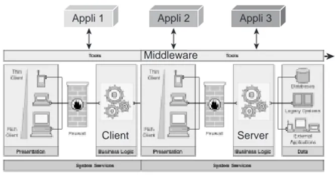
As shown in Figure 1 web (enabled/distributed) architec-ture is based on multi-tier architecarchitec-ture that separates the
presentation, business logic and data. We use this
architec-tural vision to identify and place the different IT that can be selected for building the system (Serain, 2001). This approach concerns not only the physical view as shown in Figure 1 but also the logical view (e.g. code organization, application design, etc.).
– The presentation tier allows the graphical interaction with the end-users over the network using a thin client
Internet TCP/IP; HTTP; SOAP Presentation browser; HTML; XML; OOP Business logic
OOP; XML; EJB; COM; .NET; CCM; web service
Presentation
web server; PHP; ASP; JSP; XML; OOP
Data
relational/XML data base; SQL
Local area network
TCP/IP; HTTP; SOAP; IIOP; JRMP; DCOM
Figure 1
(basically the browser) or a rich client (a dedicated GUI). The thin client presentation is performed using web browser-HTML (with script languages and XML if any). The communication with the business logic tier is based on HTTP-TCP/IP. Web dynamic technologies such as PHP, Microsoft ASP and Java JSP do not differ from this principle since these pages are compiled and executed on the web server side to generate just-in-time HTML pages displaying the graphical interface of e-business or other applications. On the other side, the rich client presentation is developed with usual Object-Oriented Programming (OOP) languages such as Java, VB, C++, C#, Delphi, etc., and the communication is carried out by protocols from middleware technology such as CORBA-IIOP, (D)COM, .NET Remoting, Java RMI-JRMP, XML-HTTP and SOAP according to component based programming. The middleware technology is the basic mechanism by which software components transparently make requests to and receive responses from each other on the same machine or across a network.
– The business logic tier encloses the application logic representing the enterprise know-how and rules. Usually this side is developed according to a component based approach with Unified Modeling Language (UML). This approach is based on advanced component models such as EJB from SUN/Java community, (D)COM and .NET from Microsoft, CORBA/CCM from OMG or web services from W3C. These components are mainly implemented following an OO programming and component intercom-munication is performed by middleware inner protocols. The components run within a software framework called
application server that provides a set of technical services
such as transaction, identification, load balancing, security, data access, persistence, etc. The business logic tier can include legacy systems, web server and portal server. – The data tier has the data persistence service with
rela-tional, XML and object data bases generally using SQL to manage data. In addition to usual data access techniques, work is being done on XML-enabled and web service data management (SQLXML).
To clarify the set of IT discussed in this article and intro-duced above using the architecture view, we propose to “classify” them according to six categories (the term technol-ogy is used in a broad sense):
– modeling technology: languages (UML), meta-model (MOF), model engineering (MDA);
– communication technology: Internet protocols (TCP/IP, HTTP), data model (XML), middleware and related communication protocol (CORBA-IIOP, DCOM, .NET Remoting, Java RMI-JRMP, SOAP);
– implementation technology: object-oriented program-ming (Java, C++, C#, Eiffel), web programprogram-ming (HTML, XML, ASP, JSP, PHP, PERL);
– packaging technology: component models and
program-ming (EJB, COM, .NET, CCM, web services); – bridging technology: COM-Java RMI, EJB-.NET; – memory technology: relational, object, XML data base,
SQL;
In order to develop such modern software applications and systems, technology selection involves many criteria. One main issue is to know if the technology is an (open) standard
technology or proprietary technology. Open standard
tech-nologies are developed by software engineering from IT/soft-ware companies who collaborate within “neutral” organiza-tions such as W3C, OASIS and OMG in accordance with a
standardization process. Such organizations represent a new
kind of actor additional to more traditional actors (academics, software-hardware-services suppliers and end-users compa-nies). It is worth noting that this trend, issued from web philos-ophy, is also present in process and petroleum engineering field. Open standard technologies are freely distributed data models or software interfaces. They provide a basis for com-munication and common approaches and enable consistency (Fay, 2003), resulting in improvements in developments, investment levels and maintenance. Clearly the common effort to develop IT standard or domain oriented standard and its world-wide adoption by a community can be a source of cost reduction because not only is the development cost shared but also the investment is expected to be more future-proof. Open computing promises many benefits: flexibility/agility, integra-tion capability, software editor independence, low develop-ment cost and adoption of technological innovation.
It is also possible to build IS from enterprise software especially for enterprise management. Enterprise Resource Planning (ERP), Enterprise Application Integration (EAI) and portal applications can provide build-in solutions that need to be tailored to enterprise context and requirements. These solutions, open source or commercial, involve stan-dard technologies and compliant web architecture.
The following sections deal with information
technolo-gies for software interoperability explicitly communication, packaging and bridging technologies.
2 COMMUNICATION TECHNOLOGY OVERVIEW 2.1 Interface, Class and Component
An interface, a key element for middleware technology, is a collection of possible functions used to specify through its operations the services of a software unit. Depending on the selected middleware technology, interfaces are developed with a specific definition programming language such as OMG IDL for CORBA, Microsoft IDL for COM, Java inter-face for RMI and WSDL for web services.
A class is an object-oriented concept. It describes a set of shared objects and belongs to the implementation step. An
object is an instance of a class. An object satisfies an
inter-face if it can be specified as the target object in each potential request described by the interface. It belongs to the imple-mentation step. However this object is distinct from the other usual objects since it collects the remote calls. The develop-ment of distributed software does not imply the choice of an actual object-oriented language (commonly C++, VB and Java) since middlewares such as COM and CORBA intro-duce the notion of pseudo-objects.
The component is a software unit that encapsulates the implementation of business process logic. Sessions (2000) stresses the difference between component and object nology, the former being a packaging and distribution
tech-nology, focusing on what a component can do, while the latter
is an implementation technology, focusing on how a component works. Objects and components are software enti-ties; objects are typically fine grained units and interact in the same computing process while components are rather coarse
grained units and are available outside their own process with
respect to interface definitions. They are issued from different software design. The difference between these two states is clearly identified in the CO standard from CO-LaN. A CO compliant component is a piece of software that includes the supplier proprietary codes—objects or not—which realize or/and use CO interfaces. The communication between CO component instances is defined unambiguously by the CO interfaces introduced in Belaud and Pons (2002). In this case the middleware technologies are CORBA and COM.
2.2 Middleware Principles
Component based applications consist of several pieces of software which are executed independently and reside on the same host or on remote hosts over a network such as intra-extra- Internet. There is a need for application integration and so for component communication through well defined inter-faces. With this aim the middleware is a set of software that
allows and organizes communication and information exchange between client component and server component.
Figure 2 shows this technology as a universal communica-tion bus, the “glue” of any IS, for integrating the different enterprise applications. It relies on a basic client-server
communication model adding a key element; the interface
defined in terms of Interface Definition Language (IDL) as defined previously.
A middleware solution provides mechanisms for interface definition and communication as well as additional services easing the use and implementation of component based soft-ware. The middleware interoperability protocol defines how the components communicate which each other. It defines marshalling process, how the data structures (integer, real, string, etc.) can be translated into network messages. There are three kinds of middleware technology: Message Oriented
Middleware (MOM), Remote Procedure Call (RPC) such
Figure 2
Middleware and client/server model.
as SOAP and Object-Oriented (OO). The interface design of OO middleware follows the object-oriented paradigm. At present the OO middleware solutions are (D)COM and .Net Remoting from Microsoft, CORBA from OMG and RMI from Java/SUN. COM, CORBA and SOAP are detailed in following sections.
All communication between software components is han-dled by middleware technology. Let us see the different alter-natives for inter-system communication technologies e.g. how our system could process requests between software components. As a first approach we distinguish two ways for exchanging information: the data model and Application
Programming Interface (API). These methods are usually
used in IS based on open computing architecture. With the data model we can use point to point software integration and file format/database integration. But this static asynchro-nous communication is not appropriate to systems that use intensive integrated calculations. Indeed the performance penalty of managing physical files can be high and can pre-vent this approach being effective for exchanging informa-tion. Therefore interoperability can be achieved by API for carrying out inter-communication processes. We can identify basically two kinds of API technologies that are commonly used in any IS project, tightly-coupled and loosely-coupled middleware. Other distinctions can be used such as distinction based on data/control/presentation integration (Wassermann, 1990).
– Tightly-coupled middleware technology: this technology requests that software components have a close relation-ship. Typically this means that the components are built on identical middleware. OO middleware are typical examples. Here the components are closely linked by
implementation dependence. For example a COM
com-ponent can interoperate with a COM comcom-ponent on Windows. However non trivial solutions exist to break this tightly coupling such as bridging technologies dis-cussed in Section 6.
Appli 1 Appli 2 Appli 3
Client Server Middleware
– Loosely-coupled middleware technology: software
components do not need to share the common technology platform and they can be deployed easily over the web. The components are loosely-coupled by implementation
independence. The web is based on this kind of protocol
with HTML/HTTP. In this field the emerging industry standard for loosely-coupled inter-communication process is SOAP.
Section 3 introduces XML for information exchange by
data model and Section 4 CORBA, COM and SOAP for information exchange by API.
2.3 Marshalling
An important notion for the API model is marshalling as remarked previously. Because distributed systems are hetero-geneous (i.e. non uniform hardware, operating systems, etc.) the exchanges of data between different components must adhere to the same conventions with respect to the internal encoding of numeric data (little-endian, big-endian), to the encoding of data over a network (unicode strings).
Marshalling is the mechanism that ensures that the para-meters of a method call are properly passed between the caller of the method and the callee (i.e. the code that imple-ments the method).
2.4 Implementation of Components
The development of software that involves components is known as component based software engineering (Brown, 1996). This is special case of object oriented software engi-neering, and development techniques and methodologies apply here also. Object oriented software development methodologies exist and the implementation of software components benefit from the use of these methodologies e.g. unified process (Chan, 2003, discusses unified process applied to COTS), iterative models for components integra-tion (Boehm, 2000).
In this paper, we address the particular problem of the implementation of software components. The main idea in components is to identify business objects that correspond to specialized activities, such as modeling, thermodynamics, numerical resolution, control and advanced control. Specialized engineers are developing new algorithms inside specialized components that implement interfaces dedicated to the corresponding domain. Each component can evolve independantly and remain compliant as long as it preserves the behavior of interfaces.
The use of UML (Booch et al., 1998) as a modeling lan-guage is the central point of software engineering tools. Some processes for software development employ standard
CArcUnit Operation CCapeOpenUnit Operation (from CAPE-OPEN) CUnitOperation Factory CUnitOperation CUnitOperationImpl 1 #p_UnitImpl 1 Creation of the units Implementation of the units: CAPE-OPEN, stub, etc. CNodeUnit Operation CBatteryLimitUnit Operation CStubUnit Operation CIndissUnit Operation Types of units: node, arc, or battery limit Figure 3
use of UML and tools to develop software of high quality with an iterative lifecycle. UML use cases are good examples to describe project requirements. The analysis is here done using class diagrams with definition of high level classes, packages and interfaces for components. The developer has a global view of the classes and packages. Classes can imple-ment different levels of complexity and heterogeneous envi-ronment. Figure 3 shows a class diagram from the INDISS project presented in Section 4.2. The dynamic behavior is modeled with sequential or collaboration diagrams. The development can be iterative due to the use of components. Some components are implemented very simply for first pro-totype; the idea is to attack risks early with an iterative lifecy-cle and to focus the process on the architecture first. It is bet-ter to detect major problems at the beginning rather than at the end of the project. Then releases are planned with evolv-ing level of detail.
Application classes are developed by application team (numerical, thermodynamic, etc.) and technical classes are developed by IT team for communication, management of middleware data types and memory allocation. This separa-tion is natural with UML class diagram. The use of middle-ware types and structures is very complex and has to be developed by a specialist IT team in specific technical classes
(Fig. 4).
UML CASE (Computer Aided Software Engineering) tools enhance the capacity for changes in round-trip
engi-neering. This is important to always have an up-to-date
UML model. Then analysis and design documents can be generated from the model. Class source code is also gener-ated from the model. The round-trip functions are essential for traceability quality requirements. The framework of a modern CASE tool is able to handle links with tools for software development:
– editor of source code;
– wizard of code environment, such as wizard to generate classes for Microsoft COM interfaces;
– configuration management tool.
Thus component based software development and UML modeling allow efficient cooperation of applicative and IT teams in an iterative lifecycle process.
3 COMMUNICATION TECHNOLOGY BY DATA MODEL
Inter-application communication by data model requires the definition of a standard data format, because the effective representation of the data is the heart of this model. In order to be adopted by major actors of application development, such a format should be standard, robust and open (i.e. can be easily tailored to specific business needs). The W3C consortium released the XML specification to address this problem.
3.1 The XML Language
EXtensible Markup Language (XML) is a simple, very flexible text format derived from SGML. Originally designed to meet the challenges of large-scale electronic publishing, XML from W3C is also playing an increasingly important role in the exchange of a wide variety of data on the web and elsewhere.
XML is an extensible file format because it is not a fixed format like HTML (a single, predefined markup language). Instead, XML is actually a meta-language—a language for describing other languages—which can be specialized to meet the needs of a particular domain, like scientific or busi-ness domains (XMLFAQ, 2004). XML targets web develop-ment, due to its syntax being close to the syntax of HTML, thus providing natural transformations to produce web docu-ments, but also targets other computer areas, such technical data handling, knowledge management, etc. Furthermore, the XML language itself is really easy to read and write, not only for specialized software tools but also for humans, which was not the case for SGML derived file formats.
XML files are based on UNICODE, which provides con-sistent representation whatever the language of the writer of the file and its reader. XML documents are generally made of elements, an element being enclosed between tags:
<molecularWeight>18.5</molecularWeight>
An attribute is an additional property of a tag:
<Element Type=”Pure”>
<Name>NITROGEN</Name> </Element>
Finally, elements can be nested, providing a hierarchical view of a data file:
<MixtureDefinition> <Element Type=”Pure”> <Name>NITROGEN</Name> </Element> <Element Type=”Pure”> <CasNo>[7732-18-5]</CasNo> </Element> </MixtureDefinition>
These simple language elements are the base of the syntax of XML files, although the language also covers notions such as namespaces, imports, typing, etc., to facilitate manage-ment of the data contained in these files.
A DTD (Document Type Definition) is a formal descrip-tion in XML declaradescrip-tion syntax of a particular type of docu-ment. It sets out what names are to be used for the different types of element, where they may occur, and how they all fit together. DTD can be inline directly in an XML file, as well as being referenced as an external resource, that may be shared by different files. Given a DTD, the validity of a XML document can be directly enforced by the XML parser
that reads the document, thus avoiding additional verifica-tions of the document. An XML schema is another language that expresses syntax constraints on XML files, but instead of DTD, this language itself is based on a XML-like syntax.
XML files basically contain data along with enclosing tags describing the semantics of the data, these files can be processed in order to transform the structure of the file. XSL (eXtensible Stylesheet Language) aims at easy transforma-tion of XML files into files of different format, XML compli-ant or not. XSL is a functional language that associates to the elements of the input XML files a set of transformations of the data contained in the input file.
One of the main use of XSL language is to transform XML files containing technical data, for example a list of data, into a more user friendly presentations, for example a table containing exactly one data per line, with associated color set depending on the nature of the data, and displayed on a standard internet browser. Figure 5 shows an typical architecture: a business application (a plant monitoring sys-tem, or a process simulation software) produces an XML compliant data file, which can be used by other, domain spe-cific, applications (like a script that will extract all events-related data in the file to produce an event log), or by a
generic tool (like a browser) which can produce a user friendly view of the data contained in the input file, with the help of business standard stylesheet.
3.2 XML Specializations
Since XML is a meta-language, it gave birth to other languages, which are dedicated to particular business domains. Amongst the many specializations of XML, we can enumerate:
– SVG is an XML sub language that is used nowadays to specify vector graphics and render them in commercial browsers.
– XMI from OMG is an XML language that can be used to describe UML entities, such as classes, diagrams, relation-ship, etc.
– CML is an XML sub language that describes the geometry of molecules.
– MathML from W3C is an XML language for mathemati-cal expressions.
– OntoCAPE from the COGents project is an XML lan-guage for (Computer Aided Process Engineering) CAPE definition. ICapeIdentification ICapeUnit Modeling class UODataMgr CO-Impl Figure 4
Domain and technical classes..
Figure 5 XSL transformation. Business application Style sheet (XSL) Script Internet browser Data (XML) Rendered HTML Event log
– WellLogML: POSC, in conjunction with others in the oil industry, initiated a project in 1999 to design an XML schema for exchange of digital well log data. Version 1.0 of the WellLogML specification was published in April 2000 after extensive review by the oil and gas industry. 3.3 Conclusion
XML allows the flexible development of user-defined docu-ment types. It provides a robust, non-proprietary, persistent, and verifiable file format for the storage and transmission of text and data both on and off the web (XMLFAQ, 2004). It can be customized to meet the users’ needs in many kinds of applications.
4 COMMUNICATION TECHNOLOGY BY API
Having seen the information exchange by data model, major technologies by API are presented and illustrated by short applications.
4.1 OMG CORBA
4.1.1 OMG
Dealing with heterogeneity in distributed computing enter-prises is not easy. In particular, the development of software applications and components that support and make efficient use of heterogeneous networked systems is very challenging. Many programming interfaces and packages currently exist to help ease the burden of developing software for a single homogeneous platform. However, few help deal with the integration of separately-developed systems in a distributed heterogeneous environment. In recognition of these prob-lems, the OMG was formed in 1989 to develop, adopt and promote standards for the development and deployment of applications in distributed heterogeneous environments. Since that time, the OMG has grown to become one of the larger software consortiums in the world, with approximately 800 members. These members contribute technology and ideas in response to Requests For Proposals (RFP) issued by the OMG. Through responses to these RFP, the OMG adopts commercially viable and supplier independent specifi-cations for the software industry.
One of the first specifications to be adopted by the OMG was the CORBA specification. The last major update of the CORBA specification was in mid-2001 when the OMG released CORBA version 3.0.
4.1.2 ORB
CORBA defines a model that specifies interoperability between distributed objects on a network in a way that is transparent to the programmer. CORBA achieves this by
defining ways for specifying the externally visible character-istics of a distributed object in a way that is implementation-independent.
This model is based on clients requesting the services from distributed objects or servers through a well-defined interface, by issuing requests to the objects in the form of events. The Object Request Broker (ORB) is in charge of delivering requests to objects and returns any responses.
Everything in the CORBA architecture depends on an ORB. The ORB acts as a central object bus over which each CORBA object interacts transparently with other CORBA objects located either locally or remotely. Each CORBA server object has an interface and exposes a set of methods. To request a service, a CORBA client acquires an object
reference to a CORBA server object. The client can now
make method calls on the object reference as if the CORBA server object resided in the client’s address space. The ORB is responsible for finding a CORBA object’s implementation, preparing it to receive requests, communicating requests to it, and carrying the reply back to the client. A CORBA object interacts with the ORB, either through the ORB interface or through an Object Adapter (OA).
4.1.3 OA
The OA serves as the glue between CORBA object imple-mentations and the ORB itself. An object adapter is an object that adapts the interface of another object to the interface expected by a caller. In other words, it is an interposed object that uses delegation to allow a caller to invoke requests on an object even though the caller does not know that object’s true interface. OA’s represent another aspect of the effort to keep the ORB as simple as possible.
4.1.4 IDL
CORBA objects are accessed through the use of an interface. OMG’s Interface Definition Language (IDL) is used to define interfaces, their attributes, methods, and parameters of those methods within the interface. OMG IDL is just a declarative language (see Fig. 6), not a programming lan-guage. As such, it is not directly used to implement distrib-uted applications. Instead, language mappings determine how OMG IDL features are mapped to the facilities of a given programming language. The OMG has standardized language mappings for Java, C, C++, Smalltalk, Python and Ada.
IDL code is processed to generate stubs (on the client side) and skeletons (on the server side). Real operations are then implemented on the server side using inheritance or del-egation. Client programs to the IDL-defined object use stub files, which provide communication through the ORB to object implementation. Figure 7 illustrates the respective stub and skeleton roles.
4.1.5 IIOP and Services
CORBA relies on a protocol called the Internet Inter-ORB Protocol (IIOP) for remote objects and CORBA defines a service-based architecture where distributed objects are only accessed through their interface without need for knowledge of the implementation details. Services can be shared by mul-tiple clients and replaced by new ones supporting the same interface without disturbing client operations. The
CORBAservices are standardized by the OMG in order to
facilitate the development of applications and higher-level services across CORBA implementation. Among CORBA-services we can mention Naming, Lifecycle, Persistent,
Transaction and Concurrency.
4.1.6 Current Status
Because CORBA is just a specification, it can be used on diverse platforms, including Mainframes, UNIX, Windows and so forth, as long as an ORB implementation exists for that platform. Currently, major ORB suppliers offer imple-mentations for numerous platforms and programming lan-guages. Numerous free implementations are also available for Java, C++ and Python. Puder (2004) maintains a compar-ative table of the different products available on the market.
4.1.7 An industrial Product: OpenSpirit
OpenSpirit (2004) is an industrial software platform based on
the CORBA architecture that offers a standard access to mul-tiple persistence solutions in the petroleum upstream domain. OpenSpirit allows independent applications to interoperate by sharing data and services. Through OpenSpirit, business applications can reach distributed data and dynamically share these data with the other connected applications, whatever the hardware, the programming language used or the software supplier. Given that integrated studies in the petroleum upstream domain require many applications from different vendors managing huge amounts of data, OpenSpirit allows end-users to significantly improve their business workflows. Petroleum engineers and geoscientists may integrate multi-vendor applications into a kind of “virtual application”. Figure 8 shows the global architecture of the product.
Figure 8
OpenSpirit architecture.
OpenSpirit is made up of:
– A Base Framework which offers a set of CORBA ser-vices and a set of specific objects (session, links, coordi-nate system, etc.). Figure 9 shows CORBA services in the OpenSpirit base framework.
– Data Modules which are domain specific (drilling, sub-surface, seismic). Each one implements a set of standard objects relevant to that domain. One or more data servers are developed for each data module and each data server is specific to a particular physical project data store or cor-porate data repository. Data servers are responsible for managing data access between the data repository and the business objects.
4.1.8 Conclusion
CORBA is a mainstream information technology thanks to its capability to make software work together, regardless of where they are located or what language their are written in. It is now widely used even in traditionally conservative IT
Data modules Base framework Datastores Clients C++/Java applications WebBased applications Drilling Sub-surface interpretation
CORBA Orb and Services
A B Client Object implementation Stub Skeleton ORB Object adapter Figure 6
Short IDL example.
Figure 7
environments such as banking and insurance. Many commer-cial and free implementations of the standard are available for the main programming languages and CORBA is proba-bly one of the best solutions to integrate legacy applications with new components based on recent technologies.
4.2 Microsoft (D)COM
Microsoft introduced the COM technology in its Windows
platform in 1995, as a replacement for previous inter-application communication technologies (OLE, etc.). The first integration was performed in the NT family of Windows. The aim of the COM technology is to provide Windows developers a set of native OS functionalities as well as an object model in order for them to be able to develop component based application running on Windows. The term COM refers to Component Object Model (Box, 1998) and the term DCOM refers to Distributed COM (Eddon and Eddon, 1998): the former is the model of the components themselves, and the latter is the middleware that ties these components together.
4.2.1 IDL and Interfaces
Each COM object must be described by an IDL file whose syntax is very similar to the OMG standardized CORBA IDL syntax. The differences lie mainly in meta-data provided by Microsoft IDL syntax, such as the specification of a Global Unique Identifiers (GUID), the specification of additional semantics provided to the COM object, or handled types.
An IDL file can be compiled and the result is a code skele-ton that can be used to implement a COM object, as well as other files than can be used to help the installation of the final executable on client computers.
An IDL can contain the declaration of the following ele-ments:
– Types declarations: typedef, enums, etc.
– Interfaces declaration: methods, types, etc.
– Co-classes: a co-class is a set of interfaces that are simul-taneously presented by a given component.
– Libraries: a library is a set of components that can be delivered together, as well as common type definitions, enumerated values, etc. A library is usually associated to a binary file (an executable file or a Dynamic Link Library), as a delivery medium of the components.
Microsoft provided several language mappings of the IDL
syntax, namely mappings for C++, C# and VB.
4.2.2 COM Objects
A COM component is a binary file that contains the imple-mentation of the methods of the interfaces it implements. Before being used by a client application, a COM component must be properly installed on a computer. The registration mechanism of a component depends on the nature of the exe-cutable it is contained in.
4.2.3 COM Component Activation
The process of creating a COM component and making it available to clients is sometimes referred to as component
Managed by Converted using Locates object using Broadcast changes Uses
Naming: Locates objects based on a multi-part hierarchical name
Trading: Locates object services that meet specified criteria
Query: Selects business objects based on a subset of the SQL92 query language
Notification: Allows objects to send typed messages via
an event channel to objects that have registered interest Property: Allows client applications to create properties at run time Life cycle: Manages the life cycle of objects
Collection: Provides a standard means to managing collections of distributed objects
Units Coordinates Reference values Project set User profile Trading Naming Query Property Life cycle Persistence Collection Notification Session Client application OpenSpirit business object Figure 9
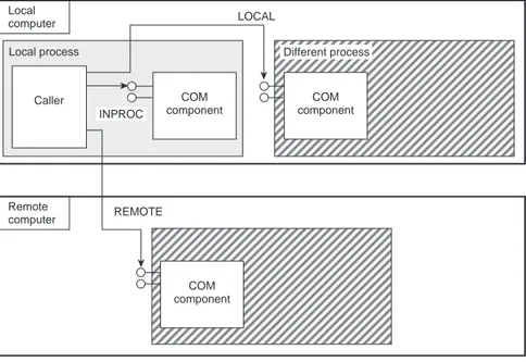
activation. Windows provides three ways to activate a
com-ponent:
– Inproc: the component is loaded in the address space of the caller (i.e. the same process), and the method calls, to the methods of the interfaces of the component, are roughly the equivalent of usual function calls in C++. – Local: the component is loaded in a different address
space than the process that requested the activation of the component. As a consequence the parameters of the meth-ods must be properly packed before being sent and calling the method in the address space of the component. – Remote: this activation mode is equivalent to the local
mode, but the address space in which the component is loaded can be physically localized on another computer. The three activations modes are shown the Figure 10 (the local process, e.g. the process of the caller is shaded in gray).
4.2.4 IUnknown Interfaces
Windows provides a special interface, the IUnknown inter-face that every COM object must implement. This interinter-face is used for basically two kinds of operations:
– Interface navigation: given an interface implemented by
a component, one can safely know if another interface is implemented by that component. This interrogation mech-anism is fundamental for modern component based soft-ware engineering. In Figure 11, we show a synthetic view of a component that provides two interfaces: the interface
IUnknown and another example interface IInterf. The
hatched region corresponds to the implementation of the
IInterf interface, provided by the developer of the compo-nent, whereas the non hatched area corresponds to the sys-tem provided implementation of the IDefault interface. This default implementation provides the QueryInterface mechanism that enables the use of the implementation code of the interface IInterf (in the hatched area) from the “basic” IUnknown interface. Furthermore, this navigation mechanism is safe, i.e. at run-time, one can safely (with-out any risk of crash of the application, as opposed to the C language operation of cast) know whether a component supports or not a given interface.
– Reference counting: since no client of a given component is able to determine if an object must be present for future method calls, each client must adhere to a reference count-ing mechanism so that the OS is the only requester of effective object destruction.
Figure 11 Interface navigation. QueryInterface IUnknown IInterf Local computer Remote computer Local process LOCAL REMOTE Caller COM component COM component COM component INPROC Different process Local process Figure 10
4.2.5 IDispatch Interfaces
One other special interface provided by Windows is the
IDispatch interface which is aimed specifically at Microsoft
applications interoperability by being natively used by the VB language. This interface provides a mechanism called late
binding, which in a word enables “textual calls” to be
per-formed on a object (e.g “call the method M on the object”), the OS being responsible for effectively calling the method on the object or rejecting the call if the object does not support the interface or if the method is not part of the interface.
This mechanism is the basis of VB/COM interoperability. Since VB is interfaced with practically every Microsoft application (Excel, Access, Word) the IDispatch interface is one of the key technologies for Windows system integration of third parties software applications.
4.2.6 Marshalling
The standard behavior of this mechanism depends on the type of the parameter that have to be marshalled:
– The standard IDL types are handled naturally (standard RPC mechanism, the values are encoded before “being sent over the wire”, Birrel and Nelson, 1984).
– UNICODE strings: the necessary memory allocations/ desallocations are performed by the OS.
– VARIANT: a VARIANT is a data structure that virtually encapsulates every IDL supported data type. The neces-sary memory allocations/desallocations are performed by the OS during the marshalling of such values.
– Interface pointers: interface pointers can be marshalled, thus enabling the remote use of an interface pointer from a remote computer (call back mechanisms).
4.2.7 Operating System Related Considerations
One important feature of COM is to be deeply integrated in Windows. This integration lies essentially in two areas: the use of OS resources and the fact that COM objects are han-dled by many Windows mechanisms, namely system admin-istration and security.
COM mechanisms make extensive use of OS resources, namely:
– the system registry, used to perform the registration of COM objects;
– activation mechanisms;
– some global objects useful to use specific instances of COM objects (Running Object Table, Global Interface Table). The integration of COM components as standard system objects enables one to apply security policies to these objects.
4.2.8 Conclusion
The COM object model is only suited to the development of components under Windows, and is often opposed to
CORBA as an object model for component based applica-tions. While the close integration in Windows can be a seri-ous advantage, mainly due to the sharing of system objects and to the fact that it requires no additional hazardous instal-lation on the computers where it is used, it also has some dis-advantages:
– COM is committed to Windows.
– COM is hard to administrate because of the inner com-plexity of OS related concepts.
– The life span of the COM technology is only dependent on Microsoft’s willingness, because Microsoft is the only actor able to decide strategic choices concerning their component technology.
Before beginning the implementation of a component based application, the question of the choice of the correct component technology must be solved. The previous ele-ments should be taken into account before proceeding to the final choice.
4.2.9 An Industrial Solution: INDISS
The INDISS simulation platform (INDustrial Integrated
Simulation Software) is designed to provide all the necessary
software tools that facilitate the implementation of applica-tions in process engineering. One single core base will sup-port various simulation environments that address different modelling and simulation needs thus avoiding duplication, additional engineering efforts and result discrepancies. Robustness and fidelity is achieved through the use of physi-cal properties and reaction kinetics. INDISS is the result of an object-oriented development over ten years. The software is coded in C++ under Windows environment. The open nature of its architecture is visible in several functionalities: – Development of unit operations is independent from
INDISS software. They can be converted into dynamic libraries and then loaded by INDISS.
– INDISS proposes its internal thermodynamic package, and an external thermodynamic package is also available to provide thermodynamic calculations in specific condi-tions.
– INDISS provides a GUI builder. This tool is used to build a customer interface based on a standard simulator. The use of technologies that allow modularity and evolu-tivity is an essential point for INDISS development. Communication with Microsoft tools and software engineer-ing effort in component based development are central. As an example, CO interfaces are integrated on the first level of design of INDISS components.
INDISS takes advantage of being developed under
Microsoft tools by providing several levels of Microsoft
interfaces. This can be done by using first versions of
Microsoft interoperability tools. INDISS is a server that
pre-sents OLE (Object Link Embedded) interfaces. These inter-faces allow simulation monitoring and access in reading and
writing mode to each variable of INDISS unit operations. It is useful to automate test sequences and provide automatic reports. This link is easy to establish under Excel or with Visual Basic.
As described in the presentation of INDISS, development of unit operations is independent from INDISS software to produced libraries. This kind of library can only be loaded inside INDISS because it uses proprietary structures for data interfaces that are linked with the INDISS executable. COM, as a middleware, adds one level of indirection between INDISS and the units. The interface is described in an IDL file that ensures the compatibility of client and server. The middleware allows also by default a link with a local or remote server. The interface is fully described in a text file. The ease with which one can describe the interaction between client and server is an important point in defining business standards, as detailed in the next paragraphs.
INDISS and DCS connection
INDISS is a tool to build process engineering simulators : it is often necessary to connect INDISS to third party software like databases or control simulators. The traditional way to connect INDISS to a control simulator for a Distributed Control Systems (DCS) is to develop a new piece of soft-ware. The proprietary API of the DCS provider is used to exchange values of control and process values.
To avoid such developments, OPC is an emerging soft-ware standard designed to provide automation applications with easy access to industrial plant floor data. OPC means initially OLE for Process Control. OLE has since been restructured and renamed to ActiveX and then COM. The goal of OPC is to define a standard interface based on COM technology that allows greater interoperability between automation and control applications; control devices; and business and office applications.
Figure 12
Components architecture.
INDISS and CAPE-OPEN
Based on CO requirements, INDISS is a component based multi layer client server architecture. As a result, INDISS is extremely flexible and facilitates the integration of third party components. The internal thermodynamic routines have been separated from the core platform and have been made avail-able as standalone components. A third party can easily plug in its own thermodynamic or CO thermodynamic property packages without going through heavy engineering when coding is necessary (Fig. 12).
This increased flexibility is of extreme importance as it primarily benefits the customer. At this present stage all the tests to integrate and operate unit operations in a dynamic mode are positive and promising and future developments will further emphasize component technology and the use of CO interfaces.
Conclusion on INDISS
The capability of INDISS to interact with other software was a basis requirement. The middleware development has increased this need by providing business components. INDISS now provides an OPC link. RSI has tested the CAPE-OPEN interface to include an external thermody-namic server inside INDISS and is developing the CAPE-OPEN interface for dynamic unit operations with other CAPE software providers. It is expected that in the next years, customers will be able to choose the software compo-nents that best match their need.
4.3 SOAP and XML-Based Middleware
HTML-HTTP act as loosely-coupled middleware
technol-ogy between the web client (browser) and the business logic
layer (web server). HTTP can be viewed as a simplified RPC middleware. Around the year 2000, Microsoft and IBM pro-posed using the XML data format over the internet protocols:
HTTP—as transport layer—and XML—as encoding format —now constitute the key underlying technologies for web
services. Web services are discussed in Section 5.4.
Many companies perform remote function calls by trans-ferring XML messages on HTTP without standardized tech-nology such as the XML-RPC specification from UserLand (2004). XML-RPC is designed to be as simple as possible, while allowing complex data structures to be transmitted, processed and returned. A set of compatible XML-RPC implementations that cover all operating systems and pro-gramming languages for Perl, Python, Java, C/C++, PHP, .NET, etc., are available. For example, Meerkat (2000) extends its open API with RPC, affording a XML-based interface to its aggregated database.
However the technology resulting from XML-HTTP most in vogue is currently SOAP (Simple Object Access Protocol) from W3C. This promising protocol is for application inter-operability (components and web services) and is not directly
CAPE-OPEN External components SEFramework RSISolver UO manager UnitOperation UnitOperation UnitOperation MaterialObject PropertyPackage ThermoSystem OPC server MMI MaterialObject MaterialTemplate
related to an object-oriented view as its name could lead one to believe. SOAP (currently in version 1.2) was delivered in June 2003, as a lightweight protocol for exchange of
infor-mation in a decentralized and distributed environment. It is
an XML based protocol that consists in three parts: an enve-lope that defines a framework for describing what is in a message and how to process it, a set of encoding rules for expressing instances of application-defined datatypes, and a convention for representing remote procedure calls and responses. SOAP can handle both the synchronous request/response pattern of RPC architectures and the asyn-chronous messages of messaging architectures. Figure 13 presents a SOAP request message in a synchronous manner from Google Web APIs beta (2004). A SOAP request is sent as a HTTP POST. The XML content consists in three main parts (Glass, 2001):
– the envelope defines the namespaces used;
– the header is an optional element for handling supplemen-tary information such as authentification, transactions, etc.; – the body performs the RPC call, detailing the method
name, its arguments and service target. In the example doGoogleSearch is the method name and key, q, start,
maxResults, etc. are the arguments.
Conclusion
Whereas CORBA, RMI, (D)COM and .NET Remoting try to adapt to the web, SOAP middleware ensures a native connec-tivity with it since it builds on HTTP, SMTP and FTP and
exploits the XML web-friendly data format. Reasons noted for the success of SOAP are its native web architecture com-pliancy, its modular design, its “simplicity”, its text-based model (in contrast to binary and not self-describing CORBA, RMI, (D)COM, .NET protocols), its error handling mecha-nism, its suitability for being the common message handling layer of web services, its standardization process and its sup-port from major software editors.
5 PACKAGING TECHNOLOGY
Middleware components run within a controlled runtime environment provided by the server editor. This packaging technology deals with the creation, management and destruc-tion of the business component. With this technology the component developer no longer needs to write “technical” code that handles transactional behavior, security, database connection pooling, etc. because the architecture delegates this task to the server supplier. These techniques are now widely used in network solutions and this section describes the different technologies.
5.1 EJB, Java Community Technology
5.1.1 Enterprise JavaBeans
Enterprise JavaBean (EJB) proposes a high-level approach
for building distributed systems. It allows application … <?xml version='1.0' encoding='UTF-8'?> <SOAP-ENV:Envelope xmlns:SOAP-ENV="http://schemas.xmlsoap.org/soap/envelope/" xmlns:xsi="http://www.w3.org/1999/XMLSchema-instance" xmlns:xsd="http://www.w3.org/1999/XMLSchema"> <SOAP-ENV:Body> <ns1:doGoogleSearch xmlns:ns1="urn:GoogleSearch" SOAP-ENV:encodingStyle="http://schemas.xmlsoap.org/soap/encoding/"> <key xsi:type="xsd:string">00000000000000000000000000000000</key> <q xsi:type="xsd:string"> Oil & Gas Scie nce and Technology </q> <start xsi: type="xsd:int">0</start>
<maxResults xsi: type="xsd:int">10</maxResults> <filter xsi:type="xsd:boolean">true</filter> <restrict xsi:type="xsd:string"></restrict>
<safeSearch xsi: type="xsd:boolean">false</safeSearch> <lr xsi:type="xsd:string"></lr> <ie xsi:type="xsd:string">latin1</ie> <oe xsi:type="xsd:string">latin1</oe> </ns1:doGoogleSearch> </SOAP-ENV:Body> </SOAP-ENV:Envelope> … Figure 13
developers to concentrate on programming only the business
logic, while removing the need to write all the common code
required for any multi-tier application development scenario. For example, the EJB developer no longer needs to write code that handles transactional behavior, security, connection pooling or threading.
In essence, EJB is a server component model for Java and is a specification for creating server-side, scalable, transac-tional, multi-user, and secure enterprise-level applications. EJB can be deployed on top of existing transaction process-ing systems includprocess-ing traditional transaction processprocess-ing mon-itors, web servers, database servers, application servers.
5.1.2 EJB Architecture
EJB are based on three key concepts:
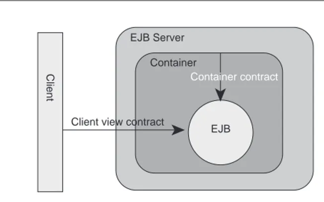
– Framework: a business component resides in a container
that provides a technical contract (naming, security, trans-action, persistence, pooling, destruction, etc.). The EJB should sign a contract with the container (implements an interface) to take advantage of the container contract
(Fig. 14).
– Proxy: a client never accesses instances of the enterprise
bean’s classes directly. It uses the enterprise bean’s remote interface. Remote call to the EJB services should be encoded on the client side and decoded on the server side. This is realized through stub and skeleton proxies. – Factory: an enterprise bean’s instance cannot be created
and removed directly. These functions are devoted to a factory called home interface.
5.1.3 Types of Enterprise Bean
Three types of enterprise bean are available, each corre-sponding to a particular business logic.
– Stateless and stateful session beans: conversational
beans. They cannot persist and are not shared between clients.
– Entity beans: represents legacy data. They persist in a data store and can be shared by different clients.
Figure 14 EJB Container.
– Message-driven beans: they can send and receive
mes-sages asynchronously. Clients do not access to a message-driven bean.
5.1.4 Benefits of Using EJB
In multi-tier architecture, it does not matter where the busi-ness logic is. With EJB, busibusi-ness logic can reside on any server, while adding additional tiers if necessary. The EJB’s containing the business logic are platform-independent and can be moved to a different, more scalable platform if neces-sary. An EJB can move from one platform to the other with-out “any” change in the business-logic code. A major high-light of the EJB specification is the support for ready-made components. This enables one to “plug and work” with
off-the-shelf EJB’s without having to develop or test them or to
have any knowledge of their inner workings.
5.1.5 EJB Communication
RMI is used as communication protocol for EJB clients. However, EJB may provide CORBA/IIOP protocol for a robust transport mechanism and pure CORBA clients can access EJB as EJB clients. Currently, a highlight of OMG’s CORBAServices is the wide range of features they provide to an enterprise application developer. In the future, rather than trying to rewrite these services, EJB server vendors may simply wrap them with a simplified API, so EJB developers can use them without being CORBA experts.
A complete description of EJB technology can be found in Gopalan (2004).
5.1.6 Java 2 Platform, Enterprise Edition (J2EE)
The Java 2 Platform, Enterprise Edition (J2EE) is a set of coordinated specifications and practices that together enable solutions for developing, deploying, and managing multi-tier server-centric applications. Building on the Java 2 Platform, Standard Edition (J2SE) the J2EE platform adds the capabili-ties necessary to provide a complete, stable, secure, and fast Java platform to the enterprise level. It significantly reduces the cost and complexity of developing and deploying multi-tier solutions.
Enterprise Java Beans are part of the J2EE platform but the platform provides also many other key technologies, for example complete web services support.
5.2 .NET, Microsoft Technology
The Microsoft response to J2EE is called .NET, and provides a set of standard components, languages, etc., aimed at the development of business applications. The different elements are:
– The CLR (Common Language Run-time) is the mecha-nism that allows every compliant language to interoperate closely (objects defined in one language can be used in
EJB Container EJB Server
Client view contract
Client
another one). Languages such as C#, VB.NET, can be compiled “on the fly” into Intermediate Language (IL): the resulting code is called managed code because the IL provides services and concepts that help the execution of such code (for instance, garbage collecting to prevent memory leaks, sandboxing to prevent malicious code being executed, etc.). On the other hand, CLR also enables the execution of unmanaged code, letting the global secu-rity policy of the virtual machine decide if it can be allowed. The CLR is the equivalent of Java virtual
machine, the IL of the Java byte code.
– .NET common classes are a set of common classes that are provided by the framework and that ease the enterprise application development. These classes are dedicated to management of files and should act as a replacement for
Microsoft foundation classes.
– ASP .NET provides classes used during Active Server Pages (ASP) creation, enabling the execution of C# code within HTML pages.
– WinForms is the technology used to create graphical applications.
– .NET remoting is the .NET middleware technology that handles the deployment of distributed applications in NET (Browning, 2002). Holloway (2002) compares it to web services.
The .NET and J2EE architectures are very similar, each having its advantages, and its respective defaults. The key technology is the programming language, i.e. C# for Microsoft .NET and Java for EJB. These object oriented lan-guages are similar in scope (simplified OO lanlan-guages), run on virtual machines and thus are naturally portable on differ-ent architectures (Windows CE, XP for .NET, all Unix fla-vors for Java). As a starting point, Farley (2000) proposes a comparison of J2EE and .NET and TMC (2002) has revisited the “famous” pet store benchmark that compares the SUN
J2EE Pet Store and the Microsoft .NET Pet Shop.
5.3 CCM, OMG Technology
CORBA Component Model (CCM) is a specification that focuses on the strength of CORBA as a server-side object model. It concentrates on issues that must be addressed to provide a complete server side middleware component model. It can be described as a platform,
cross-language superset of EJB. The CCM gives developers the
ability to quickly build web-enabled enterprise scale applica-tions while leveraging the industrial strength of CORBA. Tight integration with EJB leverages CORBA’s
cross-platform and multiple-language capabilities.
The CCM is part of the CORBA 3.0 specification. It extends the CORBA object model by defining features and services in a standard environment that enable application developers to implement, manage, configure and deploy
components that integrate with commonly used CORBA ser-vices. These server-side services include transactions, secu-rity, persistence and events. An open source implementation of a CCM platform, OpenCCM, is developed by the ObjectWeb consortium (2004).
5.4 Web Services, W3C Technology
Web technologies are more and more used for application-to-application communication as explained in previous sections. At first, software suppliers and IT experts promised this interconnected world thanks to the technology of web ser-vices. Web services propose a new paradigm for distributed computing (Bloomberg, 2001) and are one of today’s most advanced application integration solutions (Linthicum, 2003). They help business applications to contact a service broker, to find and to integrate the service from the selected service provider.
However, even if the idea of web services has generated too many promises, web services should be viewed for now
as a part of a global enterprise software solution and not as a
global technical solution. In a project, web services can be used within a general architecture relying on Java EJB or on Microsoft’s .NET framework. Newcomer (2002) gives keys for selecting between J2EE and .NET with respect to web services support.
Many projects already utilize web services, sometimes with non standard technologies, particularly for non critical intranet applications. Even if web services lack advanced functionalities, many advantages like lower integration costs, the re-use of legacy applications, the associated standardisa-tion processes and web connectivity can plead in favor of this new concept for software interoperability and integration (Manes, 2003).
5.4.1 Definition
A web service is a standardised concept of function invoca-tion relying on web protocols, independent of any technolog-ical platform (operating system, application server, program-ming language, data base and component model). BearingPoint et al. (2003) focus on the evolution from soft-ware components to web services and write: “a web service is an autonomous and modular application component, whose interfaces can be published, sought and called through Internet open standards”. We see the introduction of web ser-vices as a move from component architectures towards
Internet awareness, this context implying the use of
associ-ated technologies i.e. HTTP and XML, and an e-business economic model. Current component technology based on EJB, .NET and CCM being not fully suitable, web services provide a new component approach for providing functional-ity anywhere, anytime and to any device.