UNIVERSITÉ DE MONTRÉAL
AXIAL COMPRESSOR GAS PATH DESIGN FOR DESENSITIZATION OF
AERODYNAMIC PERFORMANCE AND STABILITY TO TIP CLEARANCE
MERT CEVIK
DÉPARTEMENT DE GÉNIE MÉCANIQUE ÉCOLE POLYTECHNIQUE DE MONTRÉAL
THÈSE PRÉSENTÉE EN VUE DE L’OBTENTION DU DIPLÔME DE PHILOSOPHIAE DOCTOR
(GÉNIE MÉCANIQUE) DÉCEMBRE 2013
UNIVERSITÉ DE MONTRÉAL
ÉCOLE POLYTECHNIQUE DE MONTRÉAL
Cette thèse intitulée:
AXIAL COMPRESSOR GAS PATH DESIGN FOR DESENSITIZATION OF
AEROSYNAMIC PERFORMANCE AND STABILITY TO TIP CLEARANCE
présentée par : CEVIK Mert
en vue de l’obtention du diplôme de : Philosophiae Doctor a été dûment accepté par le jury d’examen constitué de :
M. MUREITHI Njuki W., Ph.D., président
M. VO Huu Duc, Ph.D., membre et directeur de recherche M. TRÉPANIER Jean-Yves, Ph.D., membre
DEDICATION
ACKNOWLEDGEMENTS
I would like to express my gratitude to my supervisor Assoc. Prof. Huu Duc Vo, for his patient guidance and invaluable support throughout this study. I am particularly grateful to my friend Engin Erler for her help on using and understanding the results of her study. I would like to thank the people of Pratt & Whitney Canada for their financial and technical support and particularly to Dr. Hong Yu and Mr. Peter Townsend, for there valuable comments. Lastly I would like to express my very great appreciation to my dear wife Ece for her invaluable support.
RESUME
Le jeu d’aube est l’espace entre le bout du rotor en mouvement et le carter stationnaire d’une turbomachine. Dans un compresseur l’écoulement qui traverse ce jeu, dû à la différence de pression entre l’intrados et l’extrados de l’aube, a un impact majeur et généralement négatif sur la performance (rapport de pression et rendement) et la stabilité aérodynamique (marge contre le décrochage) du compresseur. Une augmentation du jeu d`aube, soit temporaire durant les phases d’opération transitoires, soit permanente due à l’usure, entraîne une perte de la performance et stabilité aérodynamique du compresseur et par conséquent une augmentation de la consommation de carburant et une diminution de l’enveloppe d’opération de la turbine à gaz. Bien que beaucoup de recherche a été fait pour améliorer la performance et stabilité aérodynamique des compresseurs à la valeur de design (minimale ou nominale) du jeu d’aube, très peu a été fait sur la réduction de la sensibilité de ces paramètres à l’augmentation de ce jeu. Le développement de technologies permettant de contrer cet effet mènera à des moteurs d’avion dont la performance et l’enveloppe d’opération seront plus robustes aux demandes opérationnelles et à l’usure.
Ce projet est la seconde phase d’un programme de recherche pour développer des stratégies de conception pour réduire la sensibilité de la performance et stabilité aérodynamique des compresseurs axiaux au jeu d’aube. La première phase avait porté sur des stratégies de conception d’aubes et avait mené à la découverte et l’explication de deux caractéristiques de l’écoulement permettant de réduire cette sensibilité, soit une augmentation de la quantité de mouvement méridionale entrant au bout du rotor et la réduction ou l’élimination du double écoulement de jeu. Le double écoulement de jeu est l’écoulement qui sort d’un jeu d’aube et entre dans le jeu de l’aube adjacente au lieu de convecter en aval hors du passage d’aube. Cet écoulement a un effet très négatif sur la performance et la stabilité aérodynamique du compresseur. Deux stratégies de conception impliquant le fléchissement et l’angle de décalage des aubes avaient été proposées et démontrées par simulations numériques pour exploiter ces deux caractéristiques de l’écoulement afin de réduire la sensibilité.
En tant que deuxième phase du programme de recherche, les objectifs de ce projet sont de développer des stratégies de conception de la veine gazeuse pour les compresseurs axiaux pour arriver à ce même objectif, pour évaluer la possibilité de les combiner avec les stratégies de conception d’aubes de compresseurs axiaux pour une meilleure désensibilisation et la possibilité
de les appliquer à des compresseurs non-axiaux. La recherche des stratégies de conception de la veine gazeuses reposait sur l’exploitation des deux caractéristiques d’écoulement mentionnées précédemment. Deux stratégies de conception ont été proposées. La première est la courbure de la veine gazeuse à une forme concave pour augmenter la quantité de mouvement méridionale entrant au bout du rotor. La seconde est un traitement de carter qui est composé de fentes circonférentielles en dent de scie de très faible profondeur placées sur le carter au-dessus du rotor pour réduire le double écoulement de jeu.
Une évaluation par simulations numériques de l’écoulement des deux stratégies sur le rotor axial en régime haut-subsonique utilisé comme référence dans la première phase a révélé que les fentes en dents de scie réduisaient de façon beaucoup plus significative la sensibilité ainsi que la perte de performance nominale. Une analyse détaillée du champ d’écoulement a montré que ce traitement de carter fonctionne essentiellement en améliorant le transfert de quantité de mouvement de l’écoulement du passage d’aube vers le fluide de haute entropie du double écoulement de jeu près du carter, tournant ce fluide dans le sens du courant principal, l’empêchant ainsi d’entrer dans le jeu de l’aube adjacent. Cette amélioration se fait par l’aspiration du fluide de haute entropie du double écoulement de jeu dans les fentes qui les réinjecte radialement pour se mélanger avec l’écoulement aspiré du passage d’aube du côté de l’intrados qui a pris la place de ce fluide dans le jeu d’aube.
Une étude paramétrique par simulations numériques de l’écoulement a été ensuite réalisée pour minimiser la sensibilité de la performance et stabilité aérodynamique ainsi que la perte de performance nominale. Cette étude à révélé que l’étendue axial et la position du traitement de carter ont le plus d’influence sur la réduction de la sensibilité mais aussi sur la perte de performance nominale, alors que la profondeur et le nombre de fentes ont plus d’impact sur la perte de performance nominale et la forme des fentes ont un impact modéré sur les deux. Un design amélioré du traitement de carter a été produit pour lequel les simulations numériques ont démontré une désensibilisation complète du rapport de pression et de la marge contre le décrochage et une réduction importante de la sensibilité du rendement avec seulement une très petite perte de rapport de pression nominale.
L’application du traitement de carter amélioré à la géométrie d’une aube moins sensible au jeu d`aube de la première phase du programme de recherche a démontré que ce traitement de
carter peut être combiné avec les stratégies de conception d’aubes pour diminuer d’avantage la sensibilité tout en réduisant/éliminant/renversant la perte de performance nominale.
L’efficacité de cette stratégie de traitement de carter par fentes très peu profondes a finalement été évaluée avec des simulations numériques préliminaires pour montrer qu’elle fonctionne aussi pour un étage de compresseur axial, un rotor de compresseur à écoulement mixte et un impulseur de compresseur centrifuge.
ABSTRACT
Tip clearance is the necessary small gap left between the moving rotor tip and stationary shroud of a turbomachine. In a compressor, the pressure driven flow through this gap, called tip clearance flow, has a major and generally detrimental impact on compressor performance (pressure ratio and efficiency) and aerodynamic stability (stall margin). The increase in tip clearance, either temporary during transient engine operations or permanent from wear, leads to a drop in compressor performance and aerodynamic stability which results in a fuel consumption increase and a reduced operating envelope for a gas turbine engine. While much research has looked into increasing compressor performance and stall margin at the design (minimum or nominal) tip clearance, very little attention has been paid for reducing the sensitivity of these parameters to tip clearance size increase. The development of technologies that address this issue will lead to aircraft engines whose performance and operating envelope are more robust to operational demands and wear.
The current research is the second phase of a research programme to develop design strategies to reduce the sensitivity of axial compressor performance and aerodynamic stability to tip clearance. The first phase had focused on blade design strategies and had led to the discovery and explanation of two flow features that reduces tip sensitivity, namely increased incoming meridional momentum in the rotor tip region and reduction/elimination of double leakage. Double leakage is the flow that exits one tip clearance and enters the tip clearance of the adjacent blade instead of convecting downstream out of the rotor passage. This flow was shown to be very detrimental to compressor performance and stall margin. Two rotor design strategies involving sweep and tip stagger reduction were proposed and shown by CFD simulations to exploit these features to reduce sensitivity.
As the second phase, the objectives of the current research project are to develop gas path design strategies for axial compressors to achieve the same goal, to assess their ability to be combined with desensitizing axial compressor blade design strategies and to be applied to non-axial compressors. The search for gas path design strategies was based on the exploitation of the two flow desensitizing features listed above. Two gas path design strategies were proposed and analyzed. The first was gas path contouring in the form of a concave gas path to increase incoming tip meridional momentum. The second was a casing treatment consisting of very
shallow sawtooth shaped circumferential indentations placed on the shroud over the rotor to reduce double leakage.
An assessment through CFD simulations of the two strategies on the high subsonic axial reference compressor rotor of the first phase showed that the sawtooth casing indentation provided much larger sensitivity reduction and much lower performance penalty. A detailed flow field analysis showed that this casing treatment worked essentially by enhancing the streamwise momentum transfer from the core flow to the high-entropy double leakage flow near the shroud to steer it away from the tip clearance of the adjacent blade. This enhancement involves aspiration of the high-entropy double leakage flow into the indentations and injecting it radially inward to mix with the core flow from the blade pressure side that has taken its place in the tip clearance gap.
A computational parametric study was performed to obtain preliminary design rules for minimizing performance and stall margin sensitivity to tip clearance as well as nominal performance loss. It revealed that the axial extent and location of the casing treatment have the highest impact on sensitivity reduction but also on nominal performance penalty, while groove depth and groove number impact mostly nominal performance and groove shape has only a moderate impact on both. An improved casing indentation design was produced for which CFD simulations showed a complete desensitization of pressure ratio and stall margin while reducing efficiency sensitivity significantly with only a very small penalty in nominal pressure ratio.
The application of the optimized casing indentation design to a reduced sensitivity blade geometry from the first phase showed that this casing treatment can be combined with desensitizing blade design strategies to further reduce tip sensitivity and reduce/eliminate/reverse nominal performance penalty.
The effectiveness of this shallow groove casing treatment strategy was then evaluated with preliminary CFD simulations and shown to work for an axial compressor stage, a mixed flow rotor and a centrifugal compressor impeller.
TABLE OF
CONTENTS
DEDICATION ... III ACKNOWLEDGEMENTS ... IV RESUME ... V ABSTRACT ... VIII TABLE OF CONTENTS ... X LIST OF FIGURES ...XII LIST OF TABLES ... XXI LIST OF APPENDICES ... XXIICHAPTER 1 INTRODUCTION ... 1
1.1 Background ... 1
1.2 The Problem of Tip Clearance ... 5
1.3 Desensitizing Design Features ... 9
1.4 Research Questions ... 9
1.5 Motivation and Objectives ... 10
1.6 Outline of the Thesis ... 10
CHAPTER 2 LITERATURE REVIEW ... 11
2.1 Tip Clearance Flow Physics ... 11
2.2 Tip Region Flow Management Strategies ... 17
2.2.1 Blade Design Strategies for Tip Flow Management ... 17
2.2.2 Gas Path Design Strategies and Their Effects on Desensitization ... 32
2.3 Summary ... 47
2.4 Hypothesis on Tip Desensitization of a Compressor Through Gas Path Design Strategies ... 49
CHAPTER 3 METHODOLOGY ... 50
3.1 Roadmap of the study ... 50
3.1.1 Development of Gas Path Design Strategies for Desensitization ... 50
3.2 Parametric Study and Optimization ... 57
3.2.2 Preliminary Assessment for Real Compressors ... 59
3.3 Computational Setup ... 60
3.3.1 Computational Tool Selection ... 60
3.3.2 Computational domain ... 60
3.3.3 Computational Mesh ... 65
CHAPTER 4 RESULTS ... 68
4.1 Evaluation of Gas Path Design Strategies for Desensitization ... 68
4.1.1 Contoured Gas Path ... 68
4.1.2 Casing Indentation ... 73
4.2 Parametric Study and Optimization ... 89
4.2.1 Shape ... 91
4.2.2 Depth ... 94
4.2.3 Indentation Width ... 97
4.2.4 Groove Number ... 99
4.2.5 Location ... 102
4.2.6 Final Casing Indentation Design ... 105
4.3 Integration with Blade Design Strategies ... 109
4.4 Preliminary Assessment for Real Compressors ... 111
4.4.1 Axial Compressor Stage ... 111
4.4.2 Mixed Flow Rotor ... 113
4.4.3 Centrifugal Compressor Impeller ... 116
CHAPTER 5 CONCLUSIONS AND FUTURE WORK ... 120
BIBLIOGRAPHY ... 123
LIST OF FIGURES
Figure 1-1: Schematic representation of a multi-stage axial compressor ... 1
Figure 1-2: Schematic representation of the working principle of an axial compressor stage ... 2
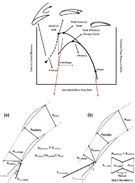
Figure 1-3: Effect of changing mass flow on compressor performance when mass flow is (a) reduced and (b) increased from the design point value ... 4
Figure 1-4: Schematic representation of flow phenomena in endwall regions (Cumpsty 1989) ... 5
Figure 1-5: Schematic representation of the tip clearance flow (Vo 2001) ... 6
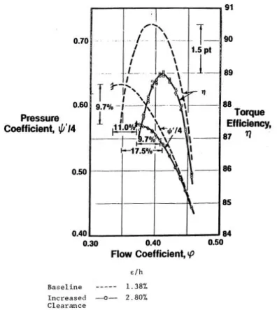
Figure 1-6: Effect of tip clearance size on pressure rise and efficiency (Wisler 1985) ... 7
Figure 1-7: Schematic of the effect of tip clearance size on a compressor map ... 8
Figure 2-1: Source of tip clearance flow vector magnitude & direction (Storer and Cumpsty 1991) ... 12
Figure 2-2: Shear/mixing layer representation (Storer and Cumpsty 1994) ... 13
Figure 2-3: The model of blockage development (Khalid, et al. 1999) ... 14
Figure 2-4: Radial distribution of blockage for the design speed and part speeds (Suder 1998) .. 14
Figure 2-5: Leading edge spillage spike stall inception criterion (Vo, et al. 2008) ... 16
Figure 2-6: Tip clearance backflow spike stall inception criterion (Vo, et al. 2008) ... 17
Figure 2-7: Schematic View of (a) Stacking Line, (b) Sweep, and (c) Lean ... 18
Figure 2-8: Schematic representations of Dihedral and Chordwise Sweep (Gallimore, et al. 2002) ... 19
Figure 2-9: Illustration of effect of forward-lean on passage pressure distribution (a) Front view (b) Side view (Denton and Xu 1998) ... 20
Figure 2-10: Illustration of effect of sweep on design characteristics (Passrucker, et al. 2003) ... 20
Figure 2-11: Measured rotor tip clearance sensitivities (a) maximum tip static pressure coefficient, (b) throttle margin, and (c) peak efficiency (McNulty, et al. 2004) ... 22
Figure 2-12: Rotor Tip Clearance Sensitivity of efficiency (a) and stall margin (b) (Wadia, et al.
2004) ... 23
Figure 2-13: Effect of the double leakage on tip leakage flow velocity components illustrated on chordwise cut of the blade (Erler 2012) ... 25
Figure 2-14: Effect of tip clearance increase on radial extent (top) and circumferential extent (bottom) of double leakage (Erler 2012) ... 27
Figure 2-15: Variation of double leakage proportion with (a) tip clearance and (b) performance for the BASE rotor with different number of blades (Erler 2012) ... 28
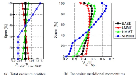
Figure 2-16: Spanwise distributions of inlet total pressure profiles and resulting incoming meridional momentum applied to BASE rotor geometry (Erler 2012) ... 28
Figure 2-17: Performance and stall margin sensitivity associated with incoming meridional momentum profiles of Figure 2-15 (Erler 2012) ... 29
Figure 2-18: Illustration of the effect of increased incoming tip meridional momentum on the tip leakage flow velocity components (Erler 2012) ... 29
Figure 2-19: 3-D views of Baseline (BASE) and FFCS rotor blade geometry (Erler 2012) ... 30
Figure 2-20: Effect of FFCS rotor blade on desensitizing flow features (Erler 2012) ... 31
Figure 2-21: 3-D views of PLS (gray) and BASE (blue) blades (Erler 2012) ... 31
Figure 2-22: Effect of PLS rotor blade on desensitizing flow features (Erler 2012) ... 32
Figure 2-23: Best casing treatment configurations examined by Takata and Tsukuda (1977) ... 33
Figure 2-24: Rotor maximum efficiency versus stall margin improvement (Fujita and Takata 1984) ... 34
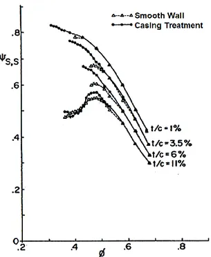
Figure 2-25: Nondimensional static pressure rise across rotor versus flow coefficient at various tip clearances for the smooth and treated casings (Smith and Cumpsty 1984) ... 34
Figure 2-26: Cross sectional view of axial slot locations (Wilke and Kau 2003) ... 36
Figure 2-27: Cross sectional views of axial slots with different overlapped portions (Danner, et al. 2009) ... 36
Figure 2-29: Casing treatment configurations investigated by Wilke and Kau (2002) ... 38
Figure 2-30: Schematic representation of axial momentum balance near the casing in the presence of circumferential grooves (Shabbir and Adamczyk 2005) ... 39
Figure 2-31: Contribution of each groove to the next axial force which is composed of net axial shear force and radially transported axial momentum (Shabbir and Adamczyk 2005) ... 40
Figure 2-32: Schematic representation of the casing modification of Zhang and Ma (2007) ... 41
Figure 2-33: Circumferential grooves investigated by Mileshin et al. (2008) ... 42
Figure 2-34: Total pressure ratio map obtained from the experiments on transonic compressor stage with smooth casing and casing treatment by Mileshin et al. (2008) ... 42
Figure 2-35: Distribution of flow features at mid-gap over the tip axial chord (a) Local tip mass flow, (b) Chordwise evolution of total tip mass flow, (c) Tip blade static pressure distribution on pressure and suction sides (Legras, et al. 2010) ... 43
Figure 2-36: Tip clearance shapes examined by Wang et al. (2002) ... 44
Figure 2-37: Tip clearance contours examined by Ma and Li (2008) ... 45
Figure 2-38: Types of tip clearance distribution studied by Shao, et al. (2007) ... 45
Figure 2-39: Side and three-dimensional views of the contoured casing of Kroger et al. (2009) 46 Figure 2-40: Vortex core trajectory and axial velocity contours for the baseline and optimized (Member 468) designs of Kroger et al. (2009) ... 47
Figure 3-1: Geometry of the BASE rotor in 3D view and blade profile at tip (Erler 2012) ... 51
Figure 3-2: Predicted effect of concave gas path on rotor inlet meridional velocity ... 52
Figure 3-3: Side views of the BASE rotor gas path versus concave gas path design ... 53
Figure 3-4: Proposed mechanism for tip desensitization by circumferential grooves casing treatment through double leakage prevention/reduction ... 54
Figure 3-5: (a) Location of double leakage flow detected through entropy of streamlines emanating from tip clearance for BASE rotor at minimum tip clearance and (b) cross-sectional view of proposed nominal casing treatment design for tip desensitization ... 55
Figure 3-6: 3D view of (a) BASE and (b) FFCS blade designs (Erler 2012) ... 59
Figure 3-7: Definition of the computation domain of the baseline rotor blade (Erler 2012) ... 62
Figure 3-8: Definition of the computation domain of a gas path contoured rotor ... 62
Figure 3-9: Computation domain of a rotor passage with casing treatment/indentation ... 63
Figure 3-10: Schematic of zonal interface between casing treatment and blade passage (Yang, et al. 2003) ... 64
Figure 3-11: Mesh of a casing indentation groove ... 66
Figure 3-12: Casing indentation streamwise mesh convergence of performance parameters ... 67
Figure 3-13: Casing indentation spanwise mesh convergence of performance parameters ... 67
Figure 3-14: Schematic representation of the modification of casing indentation cross section .. 67
Figure 4-1: Geometries of (a) the BASE rotor and (b) the concave gas path design ... 69
Figure 4-2: Spanwise loading of the BASE and concave gas path design at nominal tip clearance and design corrected mass flow rate (3.04 kg/s) ... 70
Figure 4-3: Evaluation of desensitizing flow features for concave gas path design ... 71
Figure 4-4: Tip leakage flow streamlines released from the suction surface side of the tip gap at nominal t.c. size in relative frame, for the BASE and concave gas path designs ... 71
Figure 4-5: Sensitivity analysis for concave gas path design versus BASE rotor ... 72
Figure 4-6: Entropy contours at rotor inlet and exit planes for BASE and concave gas path designs. ... 73
Figure 4-7: Nominal negative sawtooth casing indentation with BASE rotor ... 74
Figure 4-8: Spanwise loading of the BASE rotor with smooth casing and negative sawtooth casing indentation at nominal tip clearance and design corrected mass flow rate (3.04 kg/s) ... 75
Figure 4-9: Evaluation of desensitizing flow features for nominal negative sawtooth casing indentation ... 76
Figure 4-10: Tip leakage flow streamlines released from the suction surface side of the tip gap at nominal t.c. size in relative frame for smooth and negative sawtooth indentation casings ... 76 Figure 4-11: Comparison of static entropy distributions at pressure side of the tip gap of BASE
rotor with smooth casing, at nominal and maximum t.c. size ... 77 Figure 4-12: Comparison of static entropy distributions at pressure side of the tip gap of BASE
rotor with negative casing indentation, at nominal and maximum t.c. size ... 77 Figure 4-13: Sensitivity comparison of the BASE rotor with smooth casing and with negative
sawtooth indentation casing in comparison with the concave gas path design ... 78 Figure 4-14: Radial velocity contours at shroud plane for nominal casing indentation at nominal
tip clearance seen in (a) top view (b) angle view and through (c) streamlines at tip near blade pressure surface, at nominal tip clearance size (0.4% chord) ... 80 Figure 4-15: Radial velocity contours near the shroud at the axial plane shown by the dotted line
in Figure 4-14(a) ... 80 Figure 4-16: Contours of turbulent kinetic energy for outer 20% span at the axial plane shown by
the dotted line in Figure 4-14(a) ... 81 Figure 4-17: Variation of the injected mass flow rate from indentation grooves with tip clearance
size ... 82 Figure 4-18: Contours of entropy for outer 20% span at the axial plane shown by the dotted line
in Figure 4-14(a) ... 83 Figure 4-19: Chordwise distribution of non-dimensional (a) streamwise and (b) chordwise
components of tip clearance flow velocity at tip gap exit and mass-averaged over the tip clearance gap height, for the smooth casing and the casing indentation at nominal t.c. size. 84 Figure 4-20: Schematic of the effect of casing indentation on the tip region flow field through an
axial view of the rotor blade passage ... 87 Figure 4-21: Schematic of the effect of casing indentation on the tip region flow field through a
top view of the rotor blade passage ... 88 Figure 4-22: Comparison of the four flow parameters for casing indentation effectiveness as
Figure 4-23: Cross sectional view of the casing indentation shapes (a) Negative sawtooth indentation, (b) Positive sawtooth indentation (c) Constant width rectangular indentation, (d) Constant depth rectangular indentation ... 91 Figure 4-24: Comparison of the four flow parameters for casing indentation effectiveness for
different indentation shapes ... 93 Figure 4-25: Comparison of double leakage sensitivity for different casing indentation shapes 93 Figure 4-26: Cross sectional view of the negative sawtooth (nominal) casing indentation with
three different depths, (a) 0.015 inch, (b) 0.010 inch and (c) 0.0075 inch ... 95 Figure 4-27: Comparison of the four flow parameters for casing indentation effectiveness for the
smooth casing and negative sawtooth indentations of different depths, at nominal t.c. size . 96 Figure 4-28: Comparison of double leakage sensitivity for the various indentation depths ... 96 Figure 4-29: Cross sectional view of the negative sawtooth casing indentation with two different
axial extents, (a) half axial chord (nominal) and (b) one axial chord ... 97 Figure 4-30: Comparison of the four flow parameters for casing indentation effectiveness for the
smooth casing and negative sawtooth with different widths (axial extents) at nominal t.c. size ... 98 Figure 4-31: Comparison of double leakage sensitivity for the different width (axial extents) ... 99 Figure 4-32: Cross sectional view of the negative sawtooth (nominal) casing indentation with
different number of grooves (a) 3 grooved design (nominal), (b) 2 grooved design, (c) 1 grooved design ... 100 Figure 4-33: Comparison of the four flow parameters for casing indentation effectiveness for the
smooth casing and negative sawtooth indentation with different groove numbers, at nominal t.c. size ... 101 Figure 4-34: Comparison of double leakage sensitivity for the varying numbers of groove ... 101 Figure 4-35: Cross sectional view of the negative sawtooth (nominal) casing indentation at
Figure 4-36: Comparison of the four flow parameters for casing indentation effectiveness for the smooth casing and negative sawtooh casing with different locations at nominal t.c. size ... 103 Figure 4-37: Comparison of double leakage sensitivity with indentation location variations .... 104 Figure 4-38: Effect of the indentation location on chordwise distribution of tip leakage flow (a)
streamwise velocity and (b) normal velocity at tip gap exit and at nominal t.c. size ... 104 Figure 4-39: Cross sectional view and the dimensions of the final casing indentation design ... 106 Figure 4-40: Placement of the final casing indentation on the BASE rotor passage ... 107 Figure 4-41: Comparison of the four flow parameters for casing indentation effectiveness for the
smooth casing, nominal indentation and final indentation designs at nominal t.c. size... 108 Figure 4-42: Comparison of double leakage sensitivity for the final casing indentation design 108 Figure 4-43: Placement of the final casing indentation on the FFCS rotor passage ... 109 Figure 4-44: Sensitivity study of the BASE and FFCS rotors with final casing indentation design ... 110 Figure 4-45: Comparison of double leakage sensitivity of BASE and FFCS rotors with final
casing indentation design ... 110 Figure 4-46: Axial compressor stage with the final casing indentation design ... 112 Figure 4-47: Sensitivity study for the axial compressor stage ... 112 Figure 4-48: Spanwise distribution of the incidence angle at stator inlet taken from 10% axial
chord distance upstream of the stator leading edge ... 113 Figure 4-49: MFR blade with the negative sawtooth casing indentation ... 114 Figure 4-50: Comparison of the meridional velocity at rotor inlet and the change of double
leakage for the MFR with casing indentation ... 115 Figure 4-51: Tip clearance flow streamlines of the MFR with 0.01 in. t.c. size in relative frame,
for smooth casing, and casing indentation applied cases ... 115 Figure 4-52: Sensitivity study for the MFR with casing indentation ... 116
Figure 4-53: Schematical drawing of the cross sectional view and the dimensions of the
rectangular shaped casing indentation design of impeller blade ... 117
Figure 4-54: Centrifugal compressor impeller with the casing indentation ... 118
Figure 4-55: Comparison of the meridional velocity at rotor inlet and the change of double leakage for the impeller with casing indentation ... 118
Figure 4-56: Tip clearance flow streamlines of the impeller with 0.01 in. t.c. size in relative frame, for smooth casing, and casing indentation applied cases ... 119
Figure 4-57: Sensitivity study for the impeller with casing indentation ... 119
Figure A-1: Spanwise loading distribution of the BASE rotor blade (Erler 2012) ... 130
Figure A-2: Performance and Stabilitiy sensitivity of the BASE rotor (Erler 2012) ... 130
Figure B-1: Definition of interface position (Erler 2012) ... 133
Figure B-2: Tip clearance flow streamlines of negative sawtooth indentation applied rotor, at peak efficiency mass flow (3.04 kg/s) and nominal tip clearance size ... 134
Figure B-3: Contour of static entropy at tip clearance pressure surface of negative sawtooth indentation applied rotor, at peak efficiency mass flow (3.04 kg/s) and nominal tip clearance size ... 134
Figure B-4: Mass flow transfer regions (suction and injection) between the groove and rotor domains ... 136
Figure C-1: Sensitivity comparison of the BASE rotor with the smooth casing and nominal negative sawtooth indentation, analyzed with SST and k- ε turbulence models ... 137
Figure D-1: Rotor 37 streamwise mesh convergence of total-to-total pressure ratio and efficiency ... 139
Figure D-2: Rotor 37 spanwise mesh convergence of total-to-total pressure ratio and efficiency ... 139
Figure E-1: Comparison of the change of performance with tip clearance size for the smooth casing and nominal casing indentation with steady and unsteady simulations ... 140
Figure E-2: Radial velocity contours at shroud plane for nominal casing indentation at nominal tip clearance for steady and unsteady simulations ... 142 Figure E-3: Radial velocity contours at the shroud plane of nominal casing indentation at nominal
tip clearance size for unsteady simulation (a) from top view and (b) combined with streamlines ... 142 Figure E-4: Entropy contours and streamlines showing transfer of high entropy fluid by the
grooves from the pressure side to the suction side of blade tip for steady and unsteady simulations, at nominal tip clearance size ... 143 Figure E-5: Radial velocity contours at the axial plane (28% Cx) shown by the dotted line in
Figure E-2, for the steady and unsteady simulations at nominal tip clearance size ... 143 Figure F-1: Change of performance and stability of the shape configurations with tip clearance
size ... 144 Figure F-2: Change of performance and stability of the depth configurations with tip clearance
size ... 145 Figure F-3: Change of performance of the indentation width configurations with tip clearance
size ... 145 Figure F-4: Change of performance and stability of the groove number configurations with tip
clearance size ... 146 Figure F-5: Change of performance and stability of the location configurations with tip clearance
LIST OF TABLES
Table 3-1: Design parameters and Boundary Conditions for the BASE rotor blade ... 51
Table 3-2: Design parameters for the nominal desensitizing casing treatment design ... 56
Table 3-3: Design parameters of a casing indentation ... 58
Table 4-1: Summary of parameter changes in parametric study ... 89
Table 4-2: Change in tip sensitivity and nominal value of performance/aerodynamic stability for the different indentation shapes relative to the smooth casing ... 92
Table 4-3: Change in tip sensitivity and nominal value of performance/aerodynamic stability for negative sawtooth indentation with different depths relative to the smooth casing ... 95
Table 4-4: Change in tip sensitivity and nominal value of performance/aerodynamic stability for negative sawtooth indentation of different widths (axial extent) relative to the smooth casing ... 98
Table 4-5: Change in tip sensitivity and nominal value of performance/aerodynamic stability for negative sawtooth indentation with different number of grooves relative to the smooth casing ... 100
Table 4-6: Change in tip sensitivity and nominal value of performance/aerodynamic stability for negative sawtooth indentation with different locations relative to the smooth casing ... 103
Table 4-7: Design features of the final casing indentation design ... 106
Table 4-8: Change of tip sensitivity and level of performance and aerodynamic stability of the BASE rotor with nominal and final casing indentation relative to the smooth casing ... 107
Table 4-9 “Operating conditions of the mixed flow rotor (MFR)” ... 114
Table 4-10 “Operating conditions of the impeller” ... 117
Table D-1: Mesh resolutions for streamwise mesh convergence study ... 138
LIST OF APPENDICES
Appendix A Reference (BASE) Blade Design ... 129 Appendix B Definitions of Important Parameters ... 131 Appendix C Comparison of Turbulence Models ... 137 Appendix D Mesh Convergence Study for BASE Design ... 138 Appendix E Results of the Unsteady Simulations of Nominal Casing Indentation ... 140 Appendix F Performance and Stability Data of the Parametric Study ... 144
CHAPTER 1 INTRODUCTION
1.1 Background
Axial compressors are one of the central components and a key factor in fuel efficiency and stability of modern aircraft gas turbine engines. An axial compressor consists of a series of successive rotary and stationary blade rows, namely rotors and stators, as illustrated in Figure 1-1. The lower and upper endwalls are called hub and shroud, respectively, and form the gas path of a compressor. Tip clearance flow, which is the flow through the gap between the rotor tip and the stationary casing wall, is a major factor influencing compressor performance and aerodynamic stability. Although a tip clearance gap can also exist at the hub of cantilevered stators, it is a rarely used design configuration in modern compressors. The increase in tip clearance size is a common occurrence at high power regimes such as take-off, during transient operations of an engine, or as a result of rubbing wear during the service life. Such a change in tip clearance size is very detrimental to fuel consumption and stability as a result of amplification of the tip clearance flow. To appreciate the effects of tip clearance flow, this section briefly reviews the axial compressor performance characteristics.
Figure 1-2: Schematic representation of the working principle of an axial compressor stage
The working principle of an axial compressor is illustrated in Figure 1-2 through a constant span cut of a compressor stage with axial inlet and exit flows. The velocity vectors with dashed lines are in the rotating frame of reference of the rotor while those in solid blue line are at the absolute frame of the stator. These two frames are linked by the rotating speed of the compressor (U) and the combination of these three vectors is referred to as a velocity triangle. In the rotating frame of reference, the rotor blade passage acts as a diffuser with an increase in the area normal to the flow thus reducing the relative velocity and increasing the static pressure. At the same time, the flow experiences acceleration in the absolute frame of reference. Its increased kinetic energy is then converted into further static pressure rise by the stator which diffuses the flow by turning it back toward the axial direction.
A consequence of this process is the negative effect of adverse pressure gradient on the growth of blade passage boundary layers. The associated increased displacement thickness near the solid surfaces results in a reduction of effective area increase across the blade passage, thus lowering the pressure rise. Moreover, the viscous losses associated with the boundary layers reduce the pressure rise and hence the adiabatic efficiency, which are the parameters that characterize the
performance of the compressor. These losses are amplified when the compressor operates at off-design conditions, as illustrated by a plot of performance and efficiency versus mass flow at constant speed (U = constant), referred to as a speedline and depicted at the top of Figure 1-3. At the design or peak-efficiency mass flow, the angle between the relative incoming flow vector and the rotor leading edge blade angle, known as the incidence angle (i), is at a value giving minimum losses for a particular blade geometry. If the mass flow is reduced, as illustrated in Figure 1-3(a), the normal area the relative incoming flow diminishes and the area ratio across the rotor blade passage increases leading to an increase in pressure ratio. (The same can be deduced for the stator passage). However, the accompanying increase in pressure gradient and thus boundary layer thickness reduces effective area increase and decreases efficiency, which eventually overcomes the physical area increase effect and leads to a peak in pressure rise. A further drop in mass flow would eventually result in a boundary layer separation on the blade suction side and/or aerodynamic instabilities in the form of rotating stall and/or surge. Rotating stall is an aerodynamic instability characterized by the formation of a circumferential cell of axial velocity deficiency that rotates at 50-70% of the rotor speed and is usually accompanied by a sudden drop in pressure rise (Day 1993). This drop often triggers a more severe aerodynamic instability, called surge. Surge is an axisymmetric flow oscillation across the entire engine that causes a sudden drop in its power output and physical damage (Greitzer 1976). The instability point is referred to as the stall (or surge) point and its distance (either in terms of mass flow or pressure rise) from the peak efficiency (or design) point is called the stall margin or surge margin, a parameter that represents the aerodynamic stability of the compressor.
On the other hand, if the mass flow is increased from the design point value, the incoming relative flow normal area increases making the area ratio across the rotor blade passage smaller, thus reducing the pressure rise. In addition, the boundary layer losses increase on the pressure side causing a reduction in pressure rise and efficiency. (The same effect can also be deduced for the stator passage). If the mass flow is further increased, the relative velocity increases and the incoming normal area eventually becomes larger than the passage throat area, resulting in a converging-diverging configuration which chokes when flow velocity reaches Mach 1 at the passage throat as illustrated in Figure 1-3(b), resulting in a rapid increase in loss and thus a prompt drop in pressure rise and efficiency.
Figure 1-3: Effect of changing mass flow on compressor performance when mass flow is (a) reduced and (b) increased from the design point value
Since the pressure rise for a single axial compressor stage is limited, multiple stages are commonly used to achieve adequate pressure rise. However, the effects of off-design operation are then amplified. A multi-stage compressor is usually designed such that all stages operate at maximum efficiency at its design point, referred to as stage matching, mainly through dimensioning the gas path such that the flow at the inlet of each stage correspond to the optimum operation of the stage. However, away from the design point, the change in pressure rise and efficiency of the first stage results in an outlet density change that further alter the inlet flow to
the next stage away from the optimum value making its performance worse than what is should be. This effect, referred to as stage mismatch, is propagated through all downstream stages, thus amplifying pressure rise and efficiency drop, which is even more dramatic for off-design conditions involving a change in speed since stage performance is usually more affected by a change in speed than just in mass flow at the same speed.
1.2 The Problem of Tip Clearance
The explanations of performance and stability deterioration, presented at section 1.1, are based on a 2-D perspective. Nevertheless, they serve as a basis to understand the 3-D effects associated with the endwall regions in a real compressor. Figure 1-4 illustrates three dimensional flow structures in an axial compressor rotor passage that are responsible for significant losses in efficiency and pressure rise. One prominent structure is the tip clearance flow which dominates the shroud region of the passage.
Figure 1-4: Schematic representation of flow phenomena in endwall regions (Cumpsty 1989)
As mentioned previously, tip clearance or tip leakage flow is the fluid migration through the small gap between the tip of the moving rotor and the static shroud. It is driven by the pressure difference between the pressure and suction sides of the blade as illustrated in Figure 1-5. The leakage jet exits the gap with a large angle from the blade suction side and thus from the main passage flow. The interaction of the leakage jet with main passage flow generates a tip vortex near the suction side which is a source of performance deterioration through two mechanisms.
The first mechanism is loss of relative stagnation pressure from shear/mixing between the two streams which increases with the difference in flow angle and amplitude between them. This mechanism is directly related to loss in the pressure rise and efficiency. The second mechanism is linked to the low streamwise momentum region at the rotor tip region resulting from this mixing, referred to as tip blockage, which reduces the effective area ratio of the passage, thus directly affecting static pressure rise. Furthermore, the low streamwise velocity in this region causes high incidence on the downstream stator tip region which not only further reduces stage performance but can result in boundary layer and/or corner separation in the rotor passage and induces a premature stator stall.
Figure 1-5: Schematic representation of the tip clearance flow (Vo 2001)
In terms of aerodynamic instability, a recent research such as that by Vo et al. (2008) indicates that tip clearance flow has a direct impact on the stall/surge margin through two mechanisms, as will be explained in more details in chapter 2. The first one is associated with the pressure rise reaching the peak value for which tip clearance flow plays a role through its associated loss mechanisms described previously. The second mechanism is linked to the interface formed
between the incoming and tip clearance flows reaching the rotor leading edge plane, which occurs at a higher mass flow if the strength of the tip clearance flow increases.
The amount of tip clearance flow and associated detrimental effect on performance and aerodynamic stability increases with the tip clearance size. The tip clearance loss accounts for approximately 20-40% of total losses in turbomachinery (Lakshminarayana 1996). For axial compressors, this rate is expected to become higher. Hence, the increase in tip clearance size may become the most dominant factor of performance loss in an axial compressor. Moreover, an increase in tip clearance flow reduces the surge margin and therefore reduces the operating range of the compressor and thus the engine envelope. Figure 1-6 shows the substantial effect of increased tip clearance (in percentage of blade chord) on non-dimensional pressure rise, torque efficiency (alternative of total-to-total efficiency measured from torque of compressor shaft) and surge margin for a compressor stage. In this case the doubling of the tip clearance size results in a reduction in peak efficiency by 1.5 percentage points, in peak pressure rise by 9.7% and, in stall margin by 11%.
These effects are amplified at higher rotational speed as schematically shown on a compressor map in Figure 1-7 which is made up of multiple speedlines. One can observe in this figure that, at higher speeds the performance drop (shift in speedline) and stall margin drop (shift in surge line) from an increase in tip clearance size are much larger than at the lower rotational speeds.
Figure 1-7: Schematic of the effect of tip clearance size on a compressor map
In a multi-stage environment, the detrimental effect of tip clearance variation is magnified. A change in stage pressure rise and efficiency accompanying a change in tip clearance size, causes mismatching between stages similar to the effect of off-design operation described in section 1.1. Tip clearance increase could occur on a temporary basis due to differential thermal expansion between rotor and shroud during transient engine operation such as rapid engine acceleration/deceleration and maximum power operation, resulting in possible surge during critical aircraft maneuvers and take-off. On the other hand, operational wear tend to increase nominal tip clearances throughout the engine lifecycle that leads to a permanent performance degradation and increased fuel consumption. Cumpsty (1989) states that for tip clearances greater than 1% of chord in size, increasing tip clearance induces mismatching and performance deterioration inevitably. Since the current gas turbine engine technology is moving towards more
compact engine cores with smaller compressor blades, it becomes mechanically impractical to manufacture rotor blades with tip clearance below this criterion. The above arguments substantiate the need to make the compressor performance and aerodynamic stability less sensitive to the change in tip clearance size for the next generation of aircraft engine.
1.3 Desensitizing Design Features
Erler (2012) carried out the first phase of this research programme with the objective of identifying blade design strategies to desensitize performance and stall margin to tip clearance for axial compressors. The results of her study showed that two flow features reduce the sensitivity of performance and stability to tip clearance size for an axial compressor rotor, namely an increase in incoming meridional momentum in the tip region and a reduction/elimination of double leakage flow.
Double leakage flow is tip clearance fluid that enters the tip clearance of the adjacent blade instead of convecting downstream out of the local blade passage. The double leakage was shown to have a detrimental effect on the performance and aerodynamic stability and its intensity increases with tip clearance, thus explaining the drop in pressure rise, efficiency and stall margin with tip clearance increase. Its elimination was predicted and shown to have a desensitizing effect on rotor performance and stability. On the other hand, the increasing incoming meridional momentum in the tip region reduces sensitivity to tip clearance through its reduction of double leakage as well as through improved mixing with tip clearance flow. These results imply that any blade design strategy that exploits these two desensitizing features would reduce the performance and stability sensitivity to tip clearance size. Erler (2012) showed that a forward chordwise swept blade design has a desensitization effect through an increase in incoming meridional momentum at the blade tip, while reducing blade stagger in the tip region achieves desensitization through reduced double leakage.
1.4 Research Questions
To build upon and complement the research carried out by Erler (2012) which focused on to desensitization through blade design strategies for axial compressor rotors, this study investigated the following research questions:
1- Can gas path design strategies be elaborated to desensitize axial compressor rotor performance and aerodynamic stability to tip clearance increase?
2- Can such strategies be combined with axial rotor blade desensitizing strategies to further reduce performance and stability sensitivity to tip clearance size?
3- Can such gas path desensitization design strategies work in a stage (rotor-stator) environment and for non-axial compressors?
1.5 Motivation and Objectives
The objectives of this research are:
1. Develop gas path design features to render the performance and aerodynamic stability of axial compressor rotors less sensitive to change in tip clearance size.
2. Evaluate the effect of gas path desensitization design features when combined with blade desensitization design strategies for an axial compressor rotor.
3. Preliminarily assessment of the gas path desensitization features in an axial compressor stage as well as for centrifugal and mixed flow compressors.
1.6 Outline of the Thesis
This thesis consists of five chapters. This introductory chapter is followed by Chapter 2 which presents a literature review of the physics of tip clearance flow and design features to reduce the tip clearance losses as well as a review of the little existing work on performance and stability desensitization to tip clearance size. Chapter 3 outlines the methodology of the current study, followed by the results in Chapter 4. Chapter 5 gives the conclusions and future work.
CHAPTER 2 LITERATURE REVIEW
While there are very few studies in the open literature about the desensitization of compressor performance to tip clearance size, there has been a significant research since the 1980s on tip clearance flow and its effects on loss and aerodynamic stability, and on alternative compressor designs to reduce these effects. This chapter will begin by highlighting the main results from the research on tip clearance flow physics which can provide clues for this research. This review is followed by a summary of past research on tip clearance flow management for nominal performance/stability improvement and performance/stability desensitization to tip clearance size.
2.1 Tip Clearance Flow Physics
The detrimental effects of tip clearance on compressor performance had been known since the 1970s, as demonstrated in the study by Smith (1970), which showed the sensitivity of peak pressure rise to tip clearance. However the nature of tip clearance flow has only been investigated closely during the mid-1980s with advancements in computational and experimental capabilities. The studies by Inoue et al. (1986) and Inoue and Koroumaru (1989) involved hot-wire measurements on a low-speed axial-flow rotor. The former study covers the measurements at the rotor inlet and exit and the latter study performed measurements in the tip clearance region. Inoue et al. (1986) showed the existence of the tip vortex and resulting tip blockage at the rotor exit plane as well as the decrease in efficiency with increased tip clearance. Inoue and Koroumaru (1989) showed the distribution of the leakage jet along the chord and its interaction with the main flow as well as the resulting development of the tip vortex and its evolution through the blade passage.
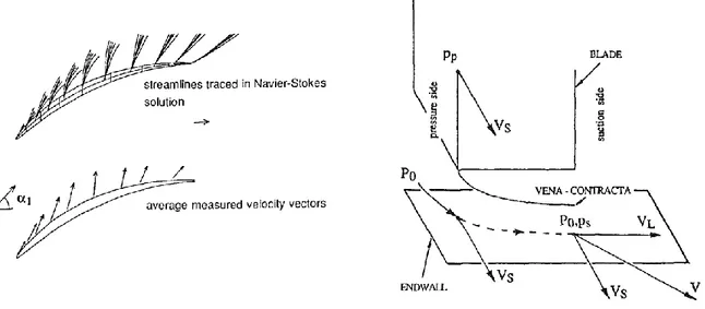
Storer and Cumpsty (1991) carried out a detailed investigation of the flow through the tip gap using cascade tests and 3-D Reynolds-Averaged Navier Stokes (RANS) CFD simulations. They decomposed the tip clearance flow into components that are normal and parallel to the local blade camber. As illustrated in Figure 2-1, their results indicated that the normal component (VL) is
essentially a pressure driven inviscid flow while the tangential component (VS) comes from the blade passage flow closest to the blade tip gap at the local chord position. Thus, the magnitude and the direction of the tip clearance flow can be predicted from the chordwise distribution of pressure difference across the gap and from the incoming axial velocity and chordwise blade camber angle distribution. The study also showed that the tip leakage flow and tip vortex strength obviously increases with the increase in tip clearance size.
Figure 2-1: Source of tip clearance flow vector magnitude & direction (Storer and Cumpsty 1991)
Storer and Cumpsty (1994) carried out further research to investigate the losses associated with tip clearance flow. They showed that tip leakage losses occur through two mechanisms. The first mechanism is associated with the shear/mixing layer between the main flow and the tip clearance flow, which have different velocity magnitudes and directions. As illustrated at the left side of Figure 2-2, the tip shear layer loss is generated by the mixing of the tip clearance flow with the incoming flow and the driving factor behind the loss generation is that these two flows have different velocity magnitudes and directions. The contour plot of viscous dissipation presented in the right plot of this figure shows the shear/mixing layer. Most of the loss in total pressure associated with tip clearance is a result of this shear/mixing layer while the loss inside the gap is comparatively very small. The second loss mechanism is the tip blockage from the
momentum deficit generated by the shear/mixing loss, which causes a reduction in effective area increase and thus in static pressure rise.
Figure 2-2: Shear/mixing layer representation (Storer and Cumpsty 1994)
Khalid et al. (1999) proposed a method to quantify the compressor endwall blockage in the three-dimensional flow field at the exit of a blade passage, which is similar to calculating a displacement thickness in a 1-D boundary layer with the mainstream velocity taken at the nearest passage core flow point to the local point in the tip blockage region. As illustrated in Figure 2-3, they also proposed a model to explain the blockage formation and growth in a compressor blade passage. This model consists of a 1-D wake generated by mixing between incoming and tip clearance flow that then grows as it convects up a positive pressure gradient to the passage exit plane. Figure 2-3(a) shows a basic illustration of the model. The leakage fluid exits the tip gap at a certain angle and total pressure (state 1) and moves through a straight line (state 2) until it meets the free stream (state 3) where it mixes with the incoming flow. The size and direction of the blockage or velocity deficit could be determined by a control volume analysis of the mixing between the two streams with mass and momentum balance. The growth of blockage from the mixing point to the exit plane (state 4) is modelled as a wake moving up a pressure gradient, as illustrated in Figure 2-3(b). The growth of the blockage could be computed by a 2D integral wake analysis. The results of blockage calculations from this model were shown to be consistent with the trends determined from numerical simulation and experimental results.
Figure 2-3: The model of blockage development (Khalid, et al. 1999)
Suder (1998) carried out an experimental study to investigate the tip blockage development in a transonic axial compressor at various rotational speeds. The study shows that the pressure and temperature rise near the end-wall region is directly related to tip clearance flow. Its results identify the blockage as the primary source for the performance and operating range drop. It was determined from the data shown in Figure 2-4 that the blockage in the shroud region is two to three times greater than the boundary layer blockage in the rest of the passage. Finally, the author analyzed the losses associated with the shock/tip leakage vortex and shock/boundary layer interactions and concluded that the strength and location of the shock has no direct relation with the tip blockage.
As mentioned earlier, tip clearance flow has also a significant impact on the aerodynamic instabilities of a compressor, particulary on rotating stall. Most of the modern compressors are tip critical which means that rotating stall originates in the rotor tip region, mainly due to tip clearance flow, rather than from blade/hub boundary layer separation.
There are two known rotating stall inception mechanisms, namely long-length scale (modal) stall inception and short-length scale (spike) stall inception. Modal stall inception is characterized by the evolution of small amplitude disturbances into a fully developed rotating stall cell. Modal stall inception occurs when the total-to-static pressure rise reaches or goes slightly beyond the peak (zero-slope) value (Camp and Day 1998). Moore and Greitzer (1986) had shown analytically that a positive slope of the total-to-static pressure rise curve corresponds to negative damping of naturally occurring circumferential perturbations which then grow into a fully-developed rotating stall cell. In this context, there is a link between tip clearance flow and modal stall inception as the tip clearance flow associated loss and blockage could cause the speedline to reach the zero-slope peak earlier than with blade and endwall boundary layers alone, as indicated by Vo et al. (2008).
Spike stall inception is the other known and most common route to rotating stall in modern compressors. It is characterized by the formation of a high amplitude perturbation localized in the rotor tip region that covers only two to three blade pitches (Day 1993). It grows into a fully-developed rotating stall cell much more rapidly than modal stall disturbances. Spike stall inception is encountered at operating conditions where the total-to-static pressure rise characteristic has a negative slope (Moore and Greitzer 1986), i.e. prior to reaching the condition for modal stall inception. Camp and Day (1998) showed by an experimental study that, spike stall inception occurs at a critical rotor tip incidence but a reduction of rotor tip incidence or increase in tip clearance could cause a change from spike to modal stall inception. Nonetheless a definitive physical explanation about its mechanism has not yet been found.
Vo et al. (2008) proposed a mechanism and two associated predictive criteria for spike stall inception. The first criterion involves the spillage of tip clearance fluid below the leading edge of the adjacent blade's tip as depicted in Figure 2-5(a). As shown in Figure 2-5(b), there is an interface marked by high entropy gradient between the low-entropy incoming flow and high-entropy tip clearance flow whose position is determined by the momentum balance between these
two streams. Originally in the blade passage, this interface moves upstream as the mass flow is reduced due to the strengthening of the tip clearance flow combined with the weakening of the incoming flow. Its position at the leading edge plane signals the onset of leading edge spillage. The second criterion is the axially reversed tip clearance flow at the trailing edge, which impinges to the pressure surface of the adjacent blade. This criterion was referred to as "tip clearance backflow" and is illustrated in Figure 2-6(a). It can be detected by the radial distribution of mass flow reaching zero at the trailing edge blade tip as shown by point 4 in Figure 2-6(b). The mechanism proposed by Vo et al. (2008) is based on the fact that the impinging tip clearance fluid tends to go upstream from the postive pressure gradient but is forced to convect downstream by the incoming flow or to leak through the adjacent blade’s tip clearance. The advent of the leading edge spillage criterion provides a low resistance path for the continued upstream movement of the impinging tip clearance fluid leading to an unstoppable tip blockage increase associated with the formation and growth of a spike perturbation. In this context, the authors state that both of the criteria should be satisfied for the occurence of spike stall inception.
An experimental study by Deppe et al. (2005) on three low-speed single-stage axial compressors and a numerical study by Hah et al. (2006) on a transonic axial compressor stage seem to confirm these two criteria. Deppe et al. (2005) also showed that tip injection directed in the tip region aimed to push the interface back into the blade passage does delay rotating stall. Nevertheless, aside from these two studies, the backflow criterion remains controversial while the leading edge criterion seems to be a common feature associated with spike stall inception.
(a) Leading Edge Spillage (b) Entropy contours in the passage
(a) Tip Clearance Backflow (b) Spanwise distribution of mass flow at the trailing edge plane Figure 2-6: Tip clearance backflow spike stall inception criterion (Vo, et al. 2008)
2.2 Tip Region Flow Management Strategies
The studies available in the open literature related with the tip clearance flow mostly focus on nominal performance and/or stability improvement by reducing the tip leakage effects with very few works covering desensitization to tip clearance change. A review of these studies will be presented in this section by classifying the related design modifications under two groups, namely blade design strategies and gas path design strategies. In the first group, the studies are further subdivided into nominal performance/stability improvement versus tip desensitization. Nevertheless, the same classification could not be made on the second group due to lack of studies focusing on desensitization.
2.2.1 Blade Design Strategies for Tip Flow Management
The descriptions of blade design strategies could be classified under two main approaches, namely modification to the blade sections (camber line, thickness distribution) and modification to the stacking line. The stacking line is a reference line passing through the aerodynamic centers of the blade profiles where the pitching moment coefficient does not vary with angle of attack, as
illustrated at Figure 2-7(a). Blade sweep (Figure 2-7(b)) involves bending the stacking line axially while blade lean (Figure 2-7(c)) means that it is bent circumferentially. As a variation/combination of these bending directions, chordwise sweep and dihedral refer to bending of the stacking line in the direction parallel and perpendicular to the chord, respectively. The dihedral in direction of rotation is known as positive dihedral and the chordwise sweep is referred to as forward when pointing in the upstream direction, as illustrated in Figure 2-8.
Nominal Performance and Stability Improvement
The numerical and experimental study of Gallimore et al. (2002) on low and high-speed axial compressors, and the numerical study of Shao et al. (2007) on axial transonic compressors by modifying the chordwise loading distribution through camber line change, both emphasized the favourable effects of loaded blades on performance. The latter study concluded that an aft-loaded blade creates less tip losses compared to its mid-aft-loaded and front-aft-loaded counterparts. Both studies attributed the observed improvements to the reduction in tip leakage losses.
Figure 2-8: Schematic representations of Dihedral and Chordwise Sweep (Gallimore, et al. 2002)
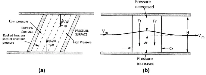
The studies involving stacking line modification mostly point out either forward swept or forward leaned blade design as promising designs to improve nominal performance. Denton and Xu (1998) proposed an explanation on the effects of forward-lean through an analytical study. They hypothesized that forward lean would not have a spanwise distribution in meridional velocity like in a radially stacked blade. The passage of a forward-leaned blade would conserve parallel constant slope isobars that would create a positive pressure gradient normal to the shroud and negative pressure gradient normal to the hub, as illustrated in Figure 2-9(a). The authors concluded that, a spanwise force (Fr) is induced by the blade to balance two pressure gradients, as
shown in Figure 2-9(b). This spanwise force creates a radial flow curvature in meridional flow (Δr) that redistributes the spanwise pressure and decreases pressure at tip region. Denton and Xu (1998) also proposed a physical explanation for the effect of sweep. They stated that at each endwall the pressure gradients normal to walls are supposed to be low as no flow could penetrate the wall. Hence for a case with aft-sweep, the blade loading should be low at the blade tip near the trailing edge since there is no blade section under that location, as illustrated in Figure 2-10(a). At the leading edge side of the blade tip, the loading should be higher as there are loaded blade sections at lower spans. Thus, an aft-swept rotor blade should be front-loaded in the tip region, while conversely a forward swept blade should have an aft-loaded tip. Passrucker et al.
(2003) later investigated blade sweep on a transonic axial rotor analytically, computationally and experimentally. The authors confirmed the explanation of Denton and Xu (1998), and pointed out the effect of sweep on repositioning the shock and reducing the accumulation of radially migrating blade boundary layer fluid, as illustrated in Figure 2-10(b) and (c). They also reported that forward swept blade increases both efficiency and stall margin.
Figure 2-9: Illustration of effect of forward-lean on passage pressure distribution (a) Front view (b) Side view (Denton and Xu 1998)
McNulty et al. (2004) and Goller et al. (2005) presented studies on low-speed axial compressor rotor, numerically and experimentally. They both reached a similar conclusion on the effect of blade sweep with Passrucker et al. (2003), as their results show performance and stall margin improvement achieved by forward sweep design. The numerical and experimental study of Benini and Biollo (2007) on transonic compressors showed the improving effect of both sweep and lean on performance and mass flow range (choking mass flow). Nonetheless, the backward sweep is noted to give slightly better performance than forward sweep which is attributed to modification of passage shock structure near tip. On the other hand, the forward lean was determined to increase the efficiency substantially by again reshaping the shock structure and reducing the shock intensity in the passage. The optimization study presented by Lee et al. (2008) based on thickness and lean modification, came up with a forward leaned blade design which achieves an improvement of 1.5 percentage points in efficiency. Nonetheless, the authors noted that the modification of blade lean had a dominant effect on the improvement of efficiency when compared to the effect of changes in blade profile.
The numerical study presented by Gallimore et al. (2002) about the effects of chordwise sweep and dihedral on a low-speed compressor stage, showed improving effects of both modifications. While chordwise swept designs were shown to improve efficiency and stall margin based on reducing shock losses, positive dihedral was shown to decrease tip loading and reduce tip leakage losses.
Desensitization to Tip Clearance Change
McNulty et al. (2004) presented a numerical and analytical study on the impact of forward swept rotors on low-speed multistage axial compressors with high and moderate tip clearances. Two rotor models were tested, with different tip loading levels achieved through modification of tip stagger and solidity. The tip loading difference causes the first rotor to have a stronger tip flow and the other a moderate tip flow, relative to each other. The forward swept rotor was shown to decrease the sensitivity of nominal performance and stall margin to tip clearance size compared to a radially stacked rotor regardless of the tip flow strength, as presented in Figure 2-11. The authors showed that forward sweep increases the streamwise momentum in the tip region and reduces the tip blockage at the rotor passage exit plane which are beneficial for performance and aerodynamic stability. Furthermore, the study pointed out double leakage