Urban Traffic Regulation
Neïla Bhouri1, Flavien Balbo1,2 and Suzanne Pinson2
Abstract: This paper proposes a bimodal urban traffic control strategy based on a multi-agent model. We call bimodal traffic, a traffic which takes into account both private vehicles and public vehicles such as buses. The objective of this research is to improve global traffic, to reduce bus delays and to improve bus regularity in congested areas of the network. In our agent-based approach, traffic regulation is obtained thanks to communication, collaboration and negotiation between hetero-geneous agents. An important feature of our system is that it allows regulation at two levels: macroscopic and microscopic levels. To model in depth regulation procedures, we have introduced special features such as priority levels for buses, computation and update of traffic signal plans, urgency index of intersection stag-es depending on the level of congstag-estion on the arcs. We have tstag-ested our strategy on a small network of six intersections, using the JADE platform. The simulation is described and preliminary results are presented. They show that our MAS strat-egy improves bus travel time while improving also private vehicles travel time, decreases bus delays and improves its regularity compared to a classical strategy called fixed-time control strategy.
1
INTRODUCTION
To improve route times of public surface transportation (bus, tramways, shut-tles, etc.), cities often use regulation systems at junctions. These systems are re-ferred as Urban Transport Control (UTC) systems. They have been extended later on to give priority to buses. The aim of these systems is to increase average speed of public transport vehicles as well as private vehicles allowed to cross a junction. Buses priority control can be operated in a passive or in an active way. Passive way consists of making off-line regulation in order to improve traffic on roads frequently used by buses. Many systems are equipped with a passive priority module; the most famous one is the TRANSYT system [18]. Active way consists of giving priority to detected buses. It needs time detection of buses and real-time modification of traffic lights in order to take into account information about buses. We can cote TUC [9] and SPPORT [10] or CRONOS [5].
The use of these systems is efficient when traffic is light or when they are used to improve a single congested bus route. However, reducing the time of bus jour-neys, although very important for operating a route, is not the only factor
consi-dered by public transport operators whose obligation is to provide passengers ser-vices e.g. keeping interval between buses.
Classical control theory used to regulate bi-modal traffic (public and private vehicles) is confronted with the modeling problem. Traffic flow can be modeled at a microscopic level i.e. modeling the behavior of each bus or at a macroscopic level i.e. modeling traffic flows. At microscopic level, TRSS (Transportation Reg-ulation Support Systems) were developed to follow a micro-regReg-ulation-based ap-proach [1], [2]. One of the weaknesses of these systems is that private vehicle traf-fic flow is hardly taken into account. If it is taken into account, this is only as an external parameter that modify the route times of buses. Another weakness is that traffic light management which is one of the key factors of traffic jams and bus delays, is not included in TRSS systems. Furthermore, microscopic modeling is time-consuming therefore not well adapted to build real time control strategies for wide urban networks. On the contrary, macroscopic modeling that is, modeling traffic flows, has the objective to reduce time spent in traffic jams so that buses re-spect their schedule [4]. We can note that macroscopic representation of buses does not allow more than an indirect consideration of bus intervals. In [14] a hybr-id model was used: macroscopic modeling for private vehicles and microscopic modeling for public transport. However The complexity of real life bimodal traffic regulation strategies shows the limits of these classical modeling approaches.
Our objective is to build a traffic control strategy for bi-modal traffic that is able to regulate both private vehicle traffic and public vehicle traffic on a whole network and not only on a single junction taking into account vehicle travel time and bus intervals. We make the hypothesis that public vehicles and private ve-hicles share the same infrastructure. This means that our proposed strategy can be implemented on real networks without a costly modification of the infrastructure with for example separate lanes for buses. However, we can easily consider a network where there are special lanes for buses as a special case of our strategy where the number of cars in front of buses will be equal to zero.
Multi-Agent modeling can give a suitable answer to the weakness highlighted above. Multi-agent paradigm is well adapted to transportation domain study since it facilitates an approach by analogy in a domain where the objective is the man-agement of distributed entities. One advantage of this approach is the explicit re-presentation of processes that it models. By reifying the components of the system to be managed, a multi-agent system allows a better understanding of a complex reality. More precisely, by underlining the components and their links makes it easier to understand regulation processes which in turn facilitates its formaliza-tion. A significant amount of research has been devoted to multi-agent approach in transportation domain. A good review can be found in [7].
We note that multi-agent systems are increasingly present in the field of traffic regulation [1] [2] [3] [12] [13] [16] [17] and [19]. The problem of traffic lights coordination on the thoroughfares of the route network has been studied in [6], [8] [12], [13] and [19]. The regulation system presented in [20] is related to traffic
as-signment using negotiation between vehicles and junctions. In [6] the authors present agent-based traffic control mechanisms to control both cars and traffic lights. However, these mechanisms do not take into account priority granted to bus on a large network where traffic is dense and where macroscopic as well as micro-scopic regulation has to be taken into account. To answer these shortcomings, we have developed a multi-agent control strategy with special features as multi-level modeling, priority level for buses, urgency index for intersection stages.
The second section describes our network model. The third section details the four types of agents that we have identified. In the fourth section we present the orchestration mechanism between agents and how agent interactions allow model-ing the regulation process at a micro and a macro level. A detailed description of agent behavior, their attributes, their objectives, as well as communication and collaboration protocols is given in section five. The sixth section provides prelim-inary results of simulation tests carried out on the Jade platform. Finally, we con-clude in the seventh section.
2
Network modeling
In our model, the urban network is represented by an oriented graph G. The set
I represents the intersections (or junctions) and the set A represent the arcs that
connect the intersections. Two intersections can be connected by one or several arcs depending on the number of lanes on the thoroughfare.
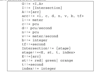
An arc is characterized by two types of information:
• Static information: its length l (in meters), its capacity c (the maximum number
of vehicles on arc i in private car unit (in pcu)), its saturation output d (the max-imum output of exits from the given arc (in pcu/second)).
• Dynamic information: the number n of vehicles on the arc (in pcu), v the
aver-age speed of the vehicles (in pcu/second), b the number of buses and tf the time necessary to evacuate the vehicles on the arc.
By private car unit (pcu), we mean that all vehicles on the arc are converted to their equivalent in private vehicles, for example a bus is 2.3 pcu depending on its length, a truck can be 2.3 or 4 pcu and so on.
An intersection is specified by a set of stages. A stage contains a set E of enter-ing arcs correspondenter-ing to compatible streams of vehicles. These streams are com-patible because they can safely cross the intersection simultaneously, else they are called antagonistic. A signal cycle is a repetition of the basic series of signal com-binations at an intersection; its duration is called time cycle. A stage is a part of the signal cycle, during which one set of streams has right of way. The set of stages represents the configuration of the junction (the permitted movements and turns). Determining the stages is a task executed offline by the traffic experts. In our
model, a stage is therefore defined thanks to its states st, its duration t and an index that gives its priority.
Our model is described in BNF notation. G::= <I,A> I::= {Intersection} A::={arc} arc::= <l, c, d, n, v, b, tf> l::= meter c::= pcu d:: pcu/second n::= pcu v::= meter/second b::= integer tf::=second Intersection::= {stage} stage::=<E, st, t, index> E::={arc}
st::= red| green| orange t::=second
index::= integer Model 1: Network Data Model.
In order to represent the different features of a network component, we use pointed notation. For example, the number of buses on arc i belonging to the stage
sa is written sa.i.b, with i ∈ sa.E.
Fig. 1: Example of an intersection with 4 arcs and two stages S1, S2. S1 allows for the clearing of the arcs a1 and a3, because the entry flow a1 and a3 can leave the junction at the same green light period. Similarly, S2 clears arcs a5 and a8.
The network is used by a number of bus routes. Each bus route is defined as the number of buses from the same origin and in the same direction, and that service a number of predefined commercial bus stops at regular time intervals. The time spent by a bus at a commercial stop is equal to the pre-set time for passengers to mount, plus additional time to regulate the interval, if required.
In real world, all this information about traffic flow and location of buses is al-ready available in Urban Transport Control (UTC) systems since all buses are
cated in real time and sensors on the road gives data about traffic flow. Our propo-sition could be connected to the UTC system and send commands to traffic lights. Our solution remains scalable because in each intersection, computation is done independently of computation done in other intersections.
3. Agent modeling
In order to identify agents and design the MAS, we represent an abstraction of the real system; every entity of the real world is associated to an agent in the vir-tual world giving a Multi-Agent System (MAS). Each agent is defined in the fol-lowing way:
Agent::= <id, pk, behavior, communication> id::= integer
communication::= send, receive Model 2: Agent generic model
pk and behavior correspond respectively to agent private knowledge and agent
behaviors; their values are defined for each type of agent, for example, pk=<E, st,
t, index> for a Stage agent. Communication primitives enable agents to
communi-cate. The primitive send (receive) enables an agent to send (to receive) a message. Performatives have the same meaning as FIPA-ACL performatives1 (see Model 3).
message::=<performative, content, sender, receiver> performative::= inform | cfp | propose | request sender::= integer
receiver::= integer Model 3: Communication model
The developed MAS is made up of the following agent-types:
Intersection Agent (IA): it is the key agent of our architecture. It is in charge of controlling an intersection with traffic lights, and of developing a traffic signal plan. The intersection agent modifies the planning of the lights according to data sent by approaching buses.
Stage Agent (SA): the traffic signal plan is elaborated thanks to the collabora-tion of the junccollabora-tion and the corresponding stage agents. Each SA determines the optimal green light split to clear the waiting vehicles on the arcs concerned by the
stage. Thus, whatever the complexity of the junction is (and its physical configura-tion), it is managed by a set of stage agents interacting with the junction agent in order to develop a plan of actions for the traffic lights.
pk::= <s>
s::= <E, st, t, index>
behavior::= <optimize-stage>
Model 4: Stage Agent model
Bus Agent (BA): it represents a bus in the real world. It circulates from one arc (current) to another (next) and communicates with its Bus Route Agent (idBRA). For each arc, it has the arc description and the id of the related intersection agents (idIA). A bus halts at commercial stops, halts at red lights and obeys the instruc-tions of the bus route agent (behavior stopRegulation). The objective of each bus agent is to minimize the time spent at traffic lights in order to minimize journey times (behavior TrafficLightRegulation).
pk::= <current, next, priority, idBRA> current::= <a, idIA>
next::= <a, idIA > a::= arc
idBRA::= integer idIA ::= integer
behavior::= <stopRegulation, trafficLightRegulation>
Model 5: Bus Agent model
Bus Route Agent (BRA): bus agents can only provide a local view of their en-vironment, more precisely, only the journey covered by the BA. Thus, local opti-mization carried out by bus agents can have a negative impact on the route, nota-bly on its regularity (i.e. the formation of bus queues or bus gaps). To tackle this problem, we propose an agent who has a global view of the bus agents on the route, and who can control and modify their behavior in order to guarantee an ef-ficient and regular service.
4. Multi-agent interaction: the traffic regulation process
Before getting on the details of the sequence of actions that follows each agent, we present the orchestration mechanism betweens the agents. The four types of agents that we have defined and their interactions allow the modeling of traffic regulation at a micro level as well as at a macro level. As said in our introduction,
few research projects have taken into account and have combined in a same sy tem these two levels of modeli
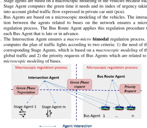
1. Stage agents are based on a macroscopic modeling of the vehicles because Stage Agent computes the green time it needs and its index of urgency taking into account global traffic flow expressed in
2. Bus Agents are based on a microscopic modeling of the vehicles. The intera tion between the agents related to buses on the network ensures a micro regulation process. The Bus Route Agent applies this regulation procedure to each Bus Agent that is late or in advance.
3. The Intersection Agent ensures a
computes the plan of traffic lights according to two criteria: 1) the need of the corresponding Stage Agents, which is based on a
global traffic and 2)
microscopic modeling
Figure 2: Multi-agent Interaction
5. Description of agent behavior
5.1 Bus Agent (BA)In order to minimize the time spent at traffic lights the b interaction agents and its hierarchical superior agent (
provide a regular service and avoid bus queues, in other words, the frequency of buses passing commercial stops must remain stable. To achieve this
BA receives orders from the
the bus is ahead with respect to the position of the preceding bus).
Behavior of a bus agent
haves in the following way:
few research projects have taken into account and have combined in a same sy tem these two levels of modeling. Figure 2 gives a global view of our proposition:
Stage agents are based on a macroscopic modeling of the vehicles because Stage Agent computes the green time it needs and its index of urgency taking
al traffic flow expressed in private car unit (pcu).
re based on a microscopic modeling of the vehicles. The intera tion between the agents related to buses on the network ensures a micro regulation process. The Bus Route Agent applies this regulation procedure to each Bus Agent that is late or in advance.
The Intersection Agent ensures a macro-micro bimodal regulation process. computes the plan of traffic lights according to two criteria: 1) the need of the corresponding Stage Agents, which is based on a macroscopic modeling
and 2) the priority requests of Bus Agents which are related to
microscopic modeling of buses.
agent Interaction
Description of agent behavior
Bus Agent (BA)In order to minimize the time spent at traffic lights the bus agent interacts and its hierarchical superior agent (BRA). All buses have to provide a regular service and avoid bus queues, in other words, the frequency of buses passing commercial stops must remain stable. To achieve this objective, the orders from the BRA (for example, stay at the stop for t seconds, if the bus is ahead with respect to the position of the preceding bus).
Behavior of a bus agent: Let t0 be the entering time of the bus agent which b
following way:
few research projects have taken into account and have combined in a same sys-ur proposition: Stage agents are based on a macroscopic modeling of the vehicles because each Stage Agent computes the green time it needs and its index of urgency taking re based on a microscopic modeling of the vehicles. The interac-tion between the agents related to buses on the network ensures a micro-regulation process. The Bus Route Agent applies this micro-regulation procedure to
regulation process. It computes the plan of traffic lights according to two criteria: 1) the need of the
macroscopic modeling of the
the priority requests of Bus Agents which are related to a
us agent interacts with buses have to provide a regular service and avoid bus queues, in other words, the frequency of objective, the (for example, stay at the stop for t seconds, if
be-When approaching a stop, the BA executes the stopRegulation behavior (see Algorithm 1). It informs the associated BRA whose identification is idBRA. The bus route agent then calculates the duration of the regulation interval and its level of priority and sends it to the bus agent. Before leaving the stop, the bus must wait during passenger loading time, as well as during the potential regulation time (not taken into account in the algorithm).
stopRegulation::= m:message
send(query, “priority”, id, next.idbra) m = receive(inform, next.idbra)
priority = m.content
Algorithm 1: Bus Agent StopRegulation algorithm
When approaching a traffic light, the BA executes the
trafficLightRegula-tion behavior (see Algorithm 2) It sends a message to retrieve informatrafficLightRegula-tion from
the arc (the number of vehicles that precede it, the length, capacity, and exit output of the arc).
With these data, the BA calculates a time-space request that is transmitted to the IA whose identification is idIA in order to prevent an eventual stop at the red light at the following intersection. The IA then attempts to satisfy the demand (see in-tersection agent below);
Calculation of a green light request. This calculation is specified by the interval of
time during which the green light is granted to the actual arc so that the bus can pass without stopping at the next junction. Let tb be the beginning time and te =
tb+δt be the ending time of the requested interval (δt is a constant value in seconds). The calculation of tb is carried out as follows: the bus enters the arc and
finds in the worst case n vehicles ahead of it, the vehicles move to the traffic lights lane to wait for the green light; the time to evacuate it is tf. In order to continue along its route, the queue of vehicles has to be dispersed before it arrives. The green light should thus be granted at the arc at the time: tb = t0 + l/v – tf.
The requested interval together with other information (id-number of the bus, its priority, the actual arc of the bus, the next arc to be traveled by the bus) are sent to the IA (at the next intersection) who attempts to modify the plan for the lights to satisfy the request. The algorithm 22 below gives the exact behavior.
trafficLightRegulation::= m: message, a: arc
send(query, current.a, id, idIA)
2 Remember that the variables are written with pointed notation. For example m.content means the content of message m, ba.id means the id of bus agent ba, a.l means the length of arc a.
m =receive(inform, idIA) a = m.content
tb= t0 + (a.l/ a.v) – a.tf
send(request, <ba.id, [tb,tb+δt],current.a, next.a,
priori-ty>, ba.id, next.idIA)
Algorithm 2: Bus Agent trafficLightRegulation algorithm 5.2 Intersection Agent (IA)
The IA is the key agent of our architecture. The IA supervises the group of stage agents (SA) who collaborate together to establish a plan for traffic lights. This plan will, on one hand, maximize the capacity of the junction and, on the oth-er hand, attempt to satisfy, as far as possible, the requested intoth-erval of buses. The IA use the static and dynamic data (Model 6).
Static data are the maximum value of the traffic light cycle (TCMAX = 120
seconds). For each cycle, there is an interval of lost time i.e. the period of orange or all red. The all red light is a period during which all the arcs from the same junction have a red light in order to clear the centre of the junction and thus pre-vent accidents. This fixed period, in conformity with the architecture of the junc-tion, does not depend on the length of the cycle. It is fixed here to a two second period after each stage.
Dynamic data are the list of received requested data from Bus agents (see Al-gorithm 2) that have been processed in order to find the useful information for the
Macro-regulation behavior and the data related to the stages. Each request is
spe-cified as follows: R = <s, tb, te, priority>, where s is the stage that will allow the passage of the given bus, tb the time when the bus is expected to arrive at the traf-fic light, te, the time when the rear of the bus leaves the arc, and finally priority is the level of bus priority defined by the bus route agent (see section below on BRA). Each stage is defined by idSA related to the intersection, its priority
(priori-ty) and the minimum time to evacuate the axes (t).
pk::= <S, TCMAX, R> S={<priority, t, idSA>} priority::=integer t::=second idSA::=integer TCMAX::= second R::={<sa, tb, te, priority>} sa::= stage tb::= second te::= second priority ::= integer behavior::= <macro-regulation>
At the end of each cycle, the IA triggers the process of calculating the traffic signal plan for the given cycle. This plan determines the duration of the green light and the ranking of each stage. When the IA receives a request, it records it in the database. The IA then decides to accept or to refuse this request at time tb. As
pro-posed in [21] for conflict resolution in planning, the modification of a traffic sig-nal plan following a priority request by a bus is as follows: 1) Extension of a stage (delay or advance), without exceeding the maximal duration of a stage; 2) Intro-duction of a new stage into the plan.
Calculation of a traffic signal plan. The plan (Plan) is calculated through the
collaboration of the Intersection agent (IA) and the corresponding Stage Agents (SAs). The IA plays the role of a manager in supervising the SAs that act as par-ticipants (see Algorithm 3).
The IA begins by forming a group of collaborators called collab_group includ-ing the list of stage agents that needs to be managed. IA initializes the variable tc that controls the size of the calculated cycle. IA sends a message request to the agents of the collab_group asking them for the time necessary to clear all the ve-hicles from their stages, beginning at instant t. Every agent of the collab_group calculates its desired green light duration and an index that measures the urgency of the stage. It sends these data to the manager (to simplify we suppose that the communication is synchronous) that updates its knowledge about this agent using the update(sa, response.content) procedure and the value of the du-ration of the proposed cycle (d = d + sa.t)).
When all the agents of collab_group have been updated, if d> tc then the man-ager has to solve a conflict using the
conflict-resolution(collab-group, tc) procedure since the size of the cycle exceeds the maximum size. Conflict is solved when d previously calculated becomes less or equal to tc. The manager selects the most urgent stage (sa = argMax(priority, col-lab_group)). It sends an accept message to the stage agent in charge of oper-ating this stage; It withdraws the corresponding stage agent from col-lab_group; It updates the variables tc, t and Plan (update(Plan, sa)); finally IA sends a request as long as collab_group is not empty.
Macro-regulation::= Plan = {} collab-group= S tc = TCMAX t= 0 Repeat { d = 0
For each (sa ∈ collab-group){
send(request, <update, t>, id, sa.idSA). response = receive(propose, sa.idSA)
update(sa, response.content) d = d + sa.t } while (d > tc) conflict-resolution(collab-group, tc) sa = argMax(priority, collab_group)
send(accept,”timeValue”, id, sa.idSA) tc = tc – sa.t
t = t + sa.t
update(Plan, sa)
collab-group = collab-group – {sa} until(size(collab-group) = 0)
Return Plan
Algorithm 3: Computation of a plan of lights
Conflict resolution. When the sum of green light durations requested by stage
agents exceeds the size of the accepted value of the cycle, the IA must restore this sum to the maximal value of the cycle. To achieve a ∆t reduction, the IA nego-tiates with the corresponding SAs using a Contract Net Protocol. The cost c of the offer is the number of buses penalized if the stage agent reduces its duration of ∆t, i.e. the number of buses that cannot pass through the intersection during ∆t.
5.3 Stage Agent (SA): This agent has a collection of both static and dynamic data as described in Model 1: Network Data Model. They represent its internal state. Static data are the list of entry arcs, the list of arcs authorized to clear if the stage is active (or green)
Dynamic data are related to 1) the state of the stage: active or inactive; 2) the
duration of green light attributed to the stage; 3) the starting time of stage execu-tion. ‘Active’ means that traffic lights controlling the arcs related to this stage are green. Vehicles are therefore authorized to depart.
Behavior of the stage agent. The SA participates to the calculation of the traffic
signal plan, and is in charge of fixing the optimal duration of green light for the given stage. When the stage agent is asked about the desired duration of green light by the corresponding intersection agent, the duration di and an index Ii that
measures the urgency of the stage, are computed and transmitted to the intersec-tion agent. If the stage agent receives confirmaintersec-tion from the IA, the stage agent stops the process. If the stage agent receives a cfp (call for propose) with a cost c, it computes an offer and sends it to the IA.
Calculation of the desired duration of the green light
{ }
i m iT
T
,..., 1max
==
where m=|E| is the number of entering arcs at the stage, ti the time necessary to clear arc i, li the length (in meter) of arc i, vi the average speed (in meter/second) on arc i, ni the number of vehicles expressed in private car unit (pcu) and di the sa-turation of arc i.(pcu/h). The first part of the equation Ti expresses the time needed
to evacuate the already formed queue at the traffic light and the second term ex-presses the time needed to evacuate vehicles entering the arc after the beginning of the green, assuming that they arrive at regular intervals
The optimal duration of green light is computed by the behavior optimize-stage (see Algorithm 4). Its value is the maximum duration to evacuate an arc of the stage.
To award priority to a bus, the urgency index of a stage is defined by the fact that the higher the index, the greater the urgency of the stage. wi=ni/ci ∈[0,1] is a parameter that indicates the degree of congestion of the arc i and e is the Euler constant. When the arc is congested, its value is 1, which means that only the first part of the equation is used
) ( i bi E i w j e e I =
∑
+ ∈We can note that if there are several buses on arc a (if bi > 1), the term ewi do-minant and therefore gives priority to stages with buses; if bi =0, the degree of con-gestion is then taken into account.
optimize-stage::= tp 0
index 0
For each (i ∈ s.E) wi = i.n/i.c
ti = (i.n/i.d) + ((i.n * i.l)/(i.c*i.v)) index = index + (ewi + ei.b)
if (ti > tp) tp = ti End For
stage.index = index
send(propose,<tp,index>, id, idIA> Algorithm 4: Optimization of a stage
5.4 Bus Route Agent (BRA)
The role of the BRA is to supervise bus agents so as to prevent a local level regulation and the creation of bus queues. In other words, this agent can modify the behavior of bus agents in two different ways: 1) directly: by keeping those buses which are ahead in the plan compared to the preceding ones, at the bus stop
i i i i i i V * C L * N ). 1 ( D N i i i w w T = + −
for a certain period of time; 2) indirectly: by modifying bus priorities. This agent has a global view of the route it operates on, and can therefore detects bus queues and react to prevent queue formation. This agent has a global view of the route it operates on, and can therefore detects bus queues and react to prevent queue for-mation. This BRA behavior is important for managing bus regularity and, as we may expect, this will increase passenger satisfaction and therefore service quality.
Internal state of the route agent. The route agent encompasses the following
data: 1) the set of arcs traveled by the bus on its route; 2) The set of stops on the route: for each stop, its position, and the distance separating it from the next stop; 3) The set of buses on the route; 4) The frequency of buses introduced onto the route. For two consecutive stops Ai and Aj, the route agent maintains the journey
time di,j of the last bus. This helps to follow the bus journey and to calculate
whether the bus is ahead or late compared to the bus immediately preceding it.
Behavior of the route agent. When a bus agent moves to a stop, the time t taken
to cover the distance Li,i-1 that separates the two stops Ai and Ai-1, is transmitted to
the route agent. The route agent then compares t to the time (di,j) taken by the
pre-ceding bus and consequently decides whether the bus is ahead or late. The route agent computes the new priority of the bus agent as well as the length of time the bus should wait at the commercial stop if it is ahead.
6. Experimentation and results
To test our bimodal control strategy, we have developed a Multi-Agent System prototype on the JADE3 platform (Java Agent Development Framework). JADE offers Java middleware with the overall aim to provide a runtime support for agents.
We have tested the strategy on a small network of six intersections (Figure 3): • The distance between two adjacent junctions belongs to [200,400] meters. • Each section comprises one or two lanes.
• The saturation flow, which is the maximum exit output of the arcs, is identical for each arc and equal 0.5 vehicle/second.
• At each entry onto the network, we have installed a source that generates pri-vate vehicles at a frequency F∈ [4 s ... 10 s].
• Some of the junctions have two stages while others have three stages.
• Two bus routes are considered on the network BR_1 and BR_2. On BR_1, the frequency of generated buses is 80 seconds and it is 180 seconds on BR_2.
3 jade.tilab.com/
We have compared the developed MAS strategy with bus priority to a fixed time strategy (same duration for all stages) with 30 seconds for each stage. We have run the simulation with these two strategies and for half-hour simulation time.
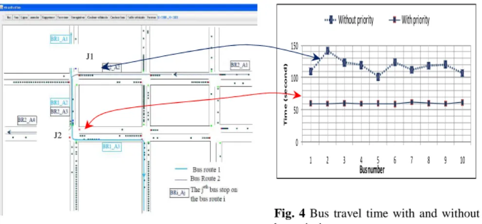
Fig. 3 The simulated network
Fig. 4 Bus travel time with and without
bus priority
Figure 4 depicts bus travel time: the higher curve shows bus travel time be-tween the stops BR1_A1 and BR1_A2 when buses do not request priority at junc-tion J1; the lowest curve show buses travel time between the two bus stops BR1_A2 and BR1_A3 when buses are asking for priority at junction J2. We can note that bus travel time improves from a mean of 120s to a mean of 60s and be-comes more regular (flat curve) when bus priority is taken into account.
Figure 5 gives the results of the two strategies for very heavy traffic conditions: Figure 5.a shows the recorded delays for buses with the two control strategies and figure 5.b shows the same kinds of curves for private vehicles.
Fig. 5.a: Bus cumulated delays Fig. 5.b Private vehicle cumulated delays
These delays correspond to the sum of time lost by all buses (resp. private ve-hicles) when they stop at traffic lights. As shown in figures 5, the MAS strategy improves both traffic of buses and traffic of private vehicles. As we can see, there is a decrease of 38% on lost time spent by buses on traffic light; for the private
0 50 100 150 1 2 3 4 5 6 7 8 9 10 T i m e ( s e c o n d )
Without priority With priority
Bus number J2
vehicles, we got a decrease of about 51%. These results can be explained because giving priority to buses decreases traffic jams thus improving private vehicles traf-fic. These results should be studied in more details: to what point these results are still valid in heavy traffic. It would be interesting to find Pareto front and multi-criteria optimization of total traffic delays and public transport delays.
7. Conclusion
In this paper, we have developed a bimodal traffic control strategy based on a multi-agent system. Unlike other approaches, our model takes into account both public transport vehicles such as buses and private vehicle traffic and studies the regulation not only in one intersection but in a whole network. The objective of this research is to improve global traffic, to reduce bus delays and to improve bus regularity in congested areas (keeping regular interval between buses) of the net-work. We have shown that an agent-based model is well adapted to study complex traffic regulation strategies. In our model, the entities representing the urban net-work communicate among themselves and negotiate in order to solve traffic regu-lating problems. First, we have shown that classical methods of control systems of traffic regulation present several weaknesses: at macroscopic level, they do not take into account mixed traffic and do not allow for the regulation of intervals be-tween buses. At microscopic level computation is time-consuming and therefore cannot be useful for regulating large networks. Secondly, we have presented the multi-agent strategy that computes traffic signal plans based on actual traffic situa-tion and on priority given to buses. Priority is given to buses taking into account intervals between buses. Thirdly, we ran a simulation prototype on the JADE plat-form. A comparison between bus travel time with and without bus priority shows that our control strategy with bur priority improves both travel time and regularity of buses. Our results also show that this bimodal MAS strategy improves condi-tions of global traffic and reduces bus delays. Additional work however is needed: a more realistic network should be defined in the simulation run and more valida-tion and more testing should be undertaken with the definivalida-tion of several indica-tors. More precisely, we plan to test our model robustness by varying the model parameters; for example, how traffic volume changes could influence the simula-tion results, and how these result variasimula-tions are statically significant.
REFERENCES
1. Balbo, F., Pinson, S., 2010. “Using intelligent agents for Transportation Regulation Support System design”, Transportation Research Part C: Emerging Technologies, Volume 18 (1), pp 140-156.
2. Balbo, F., Pinson, S., 2010. “Dynamic modeling of a disturbance in a multi-agent sys-tem for traffic regulation”, Decision Support Syssys-tems 41(1), pp 131-146
3. Bazzan A. L.. 2009. Opportunities for multiagent systems and multiagent reinforce-ment learning in traffic control, Autonomous Agents and Multi-Agent Systems 18 (3), pp 342-375.
4. Bhouri, N., Lotito P., 2005. “An intermodal traffic control strategy for private vehicle and public transport”. 10th Euro Working Group on Transportation, Poznan, Poland. pp 423-428.
5. Boillot, F., Midenet, S., Pierrelée, J.-C., 2006. The real-time urban traffic control sys-tem CRONOS, algorithm and experiments. Transportation Research, Part C, 14 (1), pp 18-38
6. Camurri M., Mamei M., and Zambonelli F., 2006. “Urban Traffic Control with Co-Fields”. Series Lecture Notes in Artificial Intelligence. V. 4389. Eds. Weyns D., Paru-nak H.V.D., and Michel F. Springer, pp 239–253.
7. Davidsson, P., Henesey, L., Ramstedt, L., 2005. An analysis of agent-based approach-es to transport logistics. Transportation Rapproach-esearch Part C: Emerging Technologiapproach-es 13 (4), pp 255–271.
8. De Oliveira D, Bazzan A.L., Lesser V, 2005. “Using Cooperative Mediation to Coor-dinate Traffic Lights: a case study”, AAMAS’05, New York, NY, USA, pp 463-470. 9. Diakaki C., Dinopoulou, V., Aboudolas, K., Papageorgiou, M., Ben-Shabat, E.,
Seid-er, E., Leibov, A., 2003. Extentions and new applications of the traffic signal control strategy TUC. Transportation Research Record, 1856.
10. Dion, F., Rakha, H., Zhang, Y. 2004. Evaluation of potential transit signal priority benefits along a fixed-time signalized arterial. Journal of Transportation Engineering, 130 (3), 294-303.
11. Doniec, A, Mandiau, R., Piechowiak, S., Espié, S. 2008. Anticipation based on con-straint processing in a multi-agent context. Journal of Autonomous Agents and Multi-Agent Systems (JAAMAS), 17, pp. 339-361.
12. Ferreira, E.D., Subrahmanian, E., Manstetten, D., 2001. “Intelligent agents in decen-tralized traffic control”. Int. IEEE-ITSC'01, Oakland (CA), USA, pp. 705-709. 13. France, J., Ghorbani, A., 2003. “A multiagent system for optimizing urban traffic”.
Int. IEEE/WIC. Washington DC, pp. 411–414
14. Kachroudi, S. and Bhouri N., 2009. “A multimodal traffic responsive strategy using particle swarm optimization”, 12th IFAC Symposium, Redondo Beach, Ca., USA. pp 13070-13078
15. Klügl, F., Rindsfüser, G. 2011. “Agent-based Route (and Mode) Choice Simulation in Real-World Networks”, Intelligent Agent Technology conference, pp 22-29
16. Mailler R. and Lesser V, 2004. “Solving distributed constraint optimization problems using cooperative mediation”, AAMAS’04, IEEE Computer Society, pp 438-445 17. Mizuno, K., Y. Fukui and S. Nishihara, 2008. “Urban Traffic Signal Control Based on
Distributed Constraint Satisfaction”, Proceedings of the 41st International Conference on System Sciences. Hawaii, pp 65.
18. Roberston, D., Vincent, R. 1975. Bus priority in a network of fixed-time signals, TRRL Repport, N° 666.
19. Roozemond D. A., 2001. “Using intelligent agents for pro-active, real-time urban in-tersection control”, European Journal for Operational Research 131, pp 293-301. 20. Vasirani, M., Ossowski, S. 2011. A Computational Market for Distributed Control of
Urban Road Traffic Systems. IEEE Transactions on Intelligent Transportation Sys-tems 12(2): 313-321.
21. Von Martial F. 1992. Coordinating Plans of Autonomous Agents, LNCS N° 610, Springer-Verlag,.