UNIVERSITÉ DE MONTRÉAL
QUANTIFYING RARE EARTH ELEMENT CONTENT IN HIGH CONCENTRATED SAMPLES BY k0-NAA
MARYAM ABDOLLAHI NEISIANI DÉPARTEMENT DE GÉNIE CHIMIQUE ÉCOLE POLYTECHNIQUE DE MONTRÉAL
MÉMOIRE PRÉSENTÉ EN VUE DE L’OBTENTION DU DIPLÔME DE MAÎTRISE ÈS SCIENCES APPLIQUÉES
(GÉNIE CHIMIQUE) AOÛT 2017
UNIVERSITÉ DE MONTRÉAL
ÉCOLE POLYTECHNIQUE DE MONTRÉAL
Ce mémoire intitulé:
QUANTIFYING RARE EARTH ELEMENT CONTENT IN HIGH CONCENTRATED SAMPLES BY k0-NAA
présenté par : ABDOLLAHI NEISIANI Maryam
en vue de l’obtention du diplôme de : Maîtrise ès sciences appliquées a été dûment accepté par le jury d’examen constitué de :
M. PATIENCE Gregory S., Ph. D., président
Mme CHILIAN Cornelia, Ph. D., membre et directrice de recherche M. CHAOUKI Jamal, Ph. D., membre et codirecteur de recherche M. SAMULEEV Pavel, Ph. D., membre
DEDICATION
ACKNOWLEDGEMENTS
I would like to extend my sincerest thanks and appreciation to those who helped me accomplish this study.
Undoubtedly, my supervisors Dr. Cornelia Chilian and Dr. Jamal Chaouki deserve to be at the top of the list. I would like to recognize Dr. Jamal Chaouki for giving me the opportunity to join his research team, for his support and encouragements. I would like to extend my gratitude to Dr. Cornelia Chilian, for her kind guidance, helpful suggestions, for her positive attitude and her patience. These past few years have been helpful in my academic progress.
I would like to express my deep sense of gratitude to all my committee members for accepting to be a member of my jury, namely, Dr. Pavel Samuleev and Dr. Gregory Patience.
I would like to acknowledge Natural Sciences and Engineering Research Council of Canada (NSERC) and Niobec, a Magris Resources Company, for funding this research. Special thanks to Dominic Downey from management team in Niobec for their guidance and support.
I would like to thank Cristina Cimpan for helping me to fulfill the experimental work during my first year in the laboratory.
I would like to extend my thanks to my colleagues and friends for sharing their friendship and knowledge with me. In addition, the members of the REE project group and especially to the project manager of the group Dr. Mohammad Latifi, the members of PEARL group, and everyone at SLOWPOKE.
Special thanks go to the secretaries and entire technical staff of the chemical engineering department and nuclear engineering department.
Finally, special recognition goes out to my family, for their support, encouragement and patience. To my incredible sister, Mania for encouraging me to reach the end of my potential and for believing in me. Your perseverance and hard work, your wisdom, your sense of discipline and above all, your love and patience, make you a real source of inspiration. To Rouzbeh, my brother in law who provided encouragement and support during the entire process as well as
continuously proofing my documents. To my sister Mitra, who always got my back during hard times with her support and love even though we were far apart.
I dedicate this thesis to my family and sincerely seek their blessing for the path ahead.
نچ اجک هب
ی
ن
؟ناباتش
-
-ا زج هب دش-اب هک -اجک نآ ره هب
ی
ن
ارس ،ارس
ی
م
Maryam Abdollahi Neisiani August 2017
RÉSUMÉ
Les terres rares (REEs) sont représentés par les éléments de la série des lanthanides incluant le scandium et yttrium. Actuellement, une grande attention est donnée aux REEs à cause de leur application dans plusieurs domaines de pointe. Dans ce contexte il y a un besoin accru pour des techniques analytiques capables de caractériser une gamme large de concentrations, en commençant avec les minéraux de faible concentration, jusqu’à leur raffinage; donc ayant des hautes concentrations en REEs. Cet étude se propose d’évaluer la performance de la méthode d’analyse par activation neutronique k0 (k0-NAA) appliquée dans le Laboratoire d’analyse par activation neutronique de Polytechnique Montréal pour la détermination avec précision des REE dans des matrices minérales de haute concentration. Les principaux facteurs qui influencent la méthode ont été investigués, en incluant les données nucléaires, la température dans les sites d’irradiation, les interférences nucléaires et spectrales, l’atténuation mutuelle des rayons gamma ainsi que l’autoprotection contre les neutrons. Afin de réaliser cet objectif, des échantillons mono-élément préparé avec des solutions standard certifiées et des oxydes standard certifiés ont été irradiés, comptés et analysés. Finalement, les protocoles d’analyse ont été optimisés en termes d’irradiation, décroissance et comptage afin de réduire le temps total d’analyse. Les incertitudes introduites par les facteurs mentionnés plus haut ont été évaluées. La capacité globale de la méthode améliorée k0-NAA pour les REEs a été mise en œuvre avec un matériel standard certifié du Projet canadien pour la certification des matériaux de référence (REE-2) avec des concentrations de 7.2 mg kg-1 pour Yb jusqu’à 9610 mg kg-1 pour Ce. Les concentrations des REEs ont été mesurées avec des incertitudes plus faibles que 7% (à 95% intervalle de confiance) et ont été consistantes avec les concentrations spécifiées dans la certification du REE-2.
ABSTRACT
The rare earth elements (REE) are comprised of lanthanide series, from lanthanum to lutetium plus scandium and yttrium. Due to the rising applications of REEs in different fields of technology a lot of attention has been drawn to the extraction of these elements. Therefore, a reliable and accurate characterization technique is required to determine variable levels of REEs starting from mineral matrices all the way to processed samples. The aim of this work is to evaluate the capability of k0-neutron activation analysis (k0-NAA) implemented at Polytechnique
Montreal for accurate determination of rare earth elements in high concentrated mineral matrices. Individual factors affecting the measurements including nuclear data used for the calculations, neutron temperature effects, nuclear interferences, spectral interferences, gamma-ray self-attenuation and neutron self-shielding were investigated. Mono rare earth element standard solutions and rare earth oxides were used to investigate these phenomena separately. Several improvements were applied to the current method. Analysis protocols were optimized in terms of irradiation, decay and counting times to obtain accurate results in shorter turnaround times, and uncertainty contributions from aforementioned factors were evaluated. To validate the overall capability of the improved k0-NAA method for REE, a certified reference material (CRM) from Canadian Certified Reference Materials Project (REE-2) with REE content ranging from 7.2 mg kg-1 for Yb to 9610 mg kg-1 for Ce was used. The REE concentration was determined with uncertainty below 7% (at 95% confidence level) and proved to be consistent with the CRM certified concentrations.
TABLE OF CONTENTS
DEDICATION ... III ACKNOWLEDGEMENTS ... IV RÉSUMÉ ... VI ABSTRACT ...VII LIST OF TABLES ... XI LIST OF FIGURES ... XIII LIST OF SYMBOLS AND ABBREVIATIONS... XIVCHAPTER 1 INTRODUCTION ... 1
1.1 Context ... 1
1.1.1 Rare earth elements ... 1
1.1.2 Analytical techniques ... 4
1.2 Objective ... 6
1.3 Plan of the dissertation ... 6
CHAPTER 2 LITERATURE REVIEW AND THEORETICAL ASPECTS OF NEUTRON ACTIVATION ANALYSIS ... 7
2.1 Introduction ... 7
2.1.1 Advantages of neutron activation analysis ... 7
2.1.2 Drawbacks of neutron activation analysis ... 7
2.1.3 Principles of neutron activation analysis ... 8
2.2 Methods of standardization ... 18
2.2.1 Absolute standardization ... 18
2.2.3 Comparator method of standardization ... 20
2.2.4 k0-method of standardization ... 21
2.3 Equipment ... 22
2.3.1 Nuclear reactors ... 22
2.3.2 The counting system ... 25
2.3.3 Detectors ... 25
CHAPTER 3 SPECIFIC OBJECTIVES AND METHODOLOGICAL ASPECTS ... 28
3.1 Sources of error ... 28
3.1.1 Nuclear data, detection efficiency ... 29
3.1.2 Interferences ... 30
CHAPTER 4 EXPERIMENTAL METHODOLODY ... 38
4.1 Experimental procedures ... 38
4.2 Spectra analysis ... 39
4.2.1 EPAA ... 39
4.2.2 Iterative gamma-ray self-attenuation correction ... 39
4.2.3 Iterative neutron self-shielding correction ... 40
4.3 SLOWPOKE reactor ... 40
CHAPTER 5 ARTICLE 1: QUANTIFYING REE CONTENT IN HIGH CONCENTRATED SAMPLES BY K0-NAA ... 42
5.1 Introduction ... 42
5.2 Experimental ... 46
5.3 Results and discussion ... 48
5.3.1 Sensitivity factors and EPAA libraries ... 48
5.3.3 Validation of k0-NAA for REEs ... 60
5.4 Conclusions ... 63
5.5 Acknowledgements ... 63
5.6 References ... 63
CHAPTER 6 GENERAL DISCUSSION AND COMPLEMENTARY NAA RESULTS ... 65
6.1 Fresh ore and concentrated ore ... 66
6.2 Beneficiation of fresh ore: Froth flotation ... 68
CHAPTER 7 CONCLUSION AND RECOMMENDATIONS ... 71
LIST OF TABLES
Table 1-1 Selected end-uses of rare earth elements ... 3 Table 4-1 SLOWPOKE design specifications ... 41 Table 5-1 Nuclear properties of REE radio isotopes used in this work: gamma energies (γ), k0 and
Q0 values for target (TI) and formed isotopes (FI) ... 49
Table 5-2 Concentrations for the REE solutions on filter paper (Xp), normalized with respect to
the standard certified values (Xcert) and corresponding coincidence summing correction
factors (COI) for three different counting positions P1, P2 and P3 ... 51 Table 5-3 Spectral Interference Correction Factors for three different counting positions, (P1, P2,
P3) ... 56 Table 5-4 Uranium Fission Interference Correction Factors for REEs ... 57 Table 5-5 Comparison of REE concentrations in oxides measured at different steps of k0-NAA
with respect to the certified values (Xcert): concentration obtained from EPAA (XEPAA), after
self-shielding correction (Xss corr), after γ-ray attenuation correction (XGA corr) ... 59
Table 5-6 Comparison of measured REE concentrations (Xlab) with the certified values (Xcert) at
different steps of k0-NAA: concentration obtained from EPAA (XEPAA), after self-shielding
correction (Xss corr), after γ-ray attenuation correction (XGA corr) ... 61
Table 5-7 Uncertainty components for the determination of REE-2 by k0-NAA ... 62 Table 6-1 Elemental analysis of fresh ore for different particle size (µm) measured with k0-NAA
at SLOWPOKE ... 66 Table 6-2 Elemental analysis of concentrated ore measured with k0-NAA at SLOWPOKE ... 67
Table 6-3 Elemental analysis of selected samples from flotation process with k0-NAA at
SLOWPOKE ... 68 Table 6-4 Metal content considering the k0-NAA result and the mass of the samples ... 69
Table 6-5 Comparison of REE concentrations measured with k0-NAA (Xlab) with respect to
LIST OF FIGURES
Figure 1-1 The lanthanide contraction ... 2
Figure 2-1 Scheme for 𝑛, 𝛾 ... 9
Figure 2-2 Decay process of radioactive 140La to stable 140Ce ... 10
Figure 2-3 Relation between neutron cross section and neutron energy for 103Rh (n, γ) ... 12
Figure 2-4 Schematic representation of a typical neutron flux spectrum in a nuclear fission reactor ... 14
Figure 2-5 Fission reaction ... 23
Figure 2-6 Cumulative chain yield for the fission of 235U as a function of mass number ... 24
Figure 2-7 Compton effect for NaI detector vs. Ge(Li) detector ... 27
Figure 3-1 Gamma-ray attenuation ... 34
LIST OF SYMBOLS AND ABBREVIATIONS
Latin alphabet
Symbol Definition Unit
A Activity Bq
a (sub) Analyte
A(sup) Nucleon number
Asp Specific activity Bq kg-1
C Correction for decay during counting
c Concentration mg kg-1
C (sub) Comparator
COI Coincidence summing correction factor
D Decay correction
E Neutron energy eV
e (sub) Epithermal
E0 Maxwellian neutron energy (0.025 eV) eV
ECd Effective Cd cut-off energy (0.55 eV in 1 mm Cd) eV
Emax Maximum energy of epithermal neutrons eV
Er,i Resonance energy eV
f Thermal to epithermal neutron flux ratio g(Tn) Westcott’s g-factor
Ge Correction factor for epithermal neutron self-shielding
Gth Correction factor for thermal neutron self-shielding
I0 Resonance integral for 1/E epithermal spectrum b
kB Boltzmann constant eV K-1
M Molar mass kg mol-1
m (sub) Monitor (Not in tm, where it denotes ‘measurement’) N Number of radioactive nuclei
𝑛(𝑣) Neutron density per unit of velocity at neutron velocity v N0 Number of target nuclei
NA Avogadro number
Q0 Ratio resonance integral (1/E) to 2200 m s-1 cross section
Q0(α) Ratio resonance integral (1/E1+α) to 2200 m s-1 cross section
td Decay time s
tir Irradiation time s
Tn Neutron temperature K
v0 Neutron velocity at temperature of 293.59 K m s-1
w Mass of the sample g
yi Fission yield of the radio-nuclide
Greek alphabet
Φ𝑒 Epithermal neutron flux per energy unit cm-2 s-1 eV-1
Φ𝑓 Fast neutron flux per energy unit cm-2 s-1 eV-1
Φ𝑡ℎ Thermal neutron flux cm-2s-1 eV-1
𝜑𝑒 Epithermal neutron flux cm-2 s-1
𝜑𝑓 Fast neutron flux cm-2 s-1
𝜑𝑡ℎ Thermal neutron flux cm-2 s-1
α Epithermal neutron flux shape factor
𝛾 Gamma-ray abundance (emission probability) 𝜀𝑑 Detection efficiency at distance d
θ Isotopic abundance
λ Decay constant s-1
σ Thermal neutron activation cross-section b
Abbreviation
ADC Digital Converter
CRM Certified reference material HPGe High purity germanium HREE Heavy rare earth elements
ICP-AES Inductively coupled plasma atomic emission spectroscopy ICP-MS Inductively coupled plasma mass spectrometry
ICP-OES Inductively coupled plasma optical emission spectrometry INAA Instrumental neutron activation analysis
IRMM Institute for Reference Materials and Measurements IUPAC International Union of Pure and Applied Chemistry LREE Light rare earth elements
MCA Multi- Channel Analyzer
MIP-AES Microwave plasma-atomic emission spectrometer NAA Neutron activation analysis
PGNAA Prompt Gamma Neutron Activation Analysis REE Rare earth elements
REO Rare earth oxide
CHAPTER 1
INTRODUCTION
1.1 Context
1.1.1 Rare earth elements
“These elements perplex us in our searches, baffle us in our speculations, and haunt us in our very dreams. They stretch like an unknown sea before us—mocking, mystifying, and murmuring strange revelations and possibilities”
Sir William Crookes, February 16, 1887
“Rare earths: neither rare, nor earths.”
BBC World Service, March 23, 2014
Rare earth elements (REEs) are the fifteen lanthanide series plus yttrium and scandium according to International Union of Pure and Applied Chemistry (IUPAC) [1]. These elements are split into two groups; From La to Eu are referred to as light rare earth elements (LREEs) and heavy rare elements (HREEs) include the remaining lanthanide series from Gd to Lu plus yttrium. Scandium is not included in either the light or the heavy ones [2].
Generally, the ionic radii of elements in periodic table increases with increasing the atomic number. However, this rule does not apply to the rare earth elements and their ionic radii decreases with increasing the atomic number which is referred to as lanthanide contraction [3]. This can be explained by the fact that as the atomic number increases, the increasing positive charge on the nucleus will cause the electron shell of these elements to draw closer to the nucleus while the effect of an added electron is shielded since it is filling the inner 4f sub-shell [4].
Ionic radii of rare earth elements are shown in Figure 1-1. Their similarity in ionic radii is the explanation for their interchangeability and the difficulty to separate them in most minerals. It also explains why yttrium is considered as one of the heavy rare earth elements (similar ionic
radius and chemical properties) and scandium, with a smaller ionic radius, is excluded from the categories [3].
Figure 1-1 The lanthanide contraction (taken from [5])
Contrary to their name, rare earth elements are more abundant in the Earth’s crust than commonly exploited elements including platinum group and mercury [2]. Only promethium does not exist naturally. However, the rare earth elements are commonly found in very low concentrations. They are mostly in forms of oxides, silicates, carbonates, phosphates and halides instead of pure metals [5]. There more than 250 kind of minerals discovered that contains rare earth elements with concentrations as low as 10 mg kg-1 in some cases [6]. The most important rare earth bearing minerals that are exploited commercially are bastnäsite and monazite with an average rare earth oxide (REO) content of 75 and 61 percent, respectively [7].
The global demand for rare earth elements has increased in recent years due to their growing applications in numerous technologies such as electronic displays, permanent magnets and renewable energy. Table 1-1 illustrates some of the end uses of rare earth elements.
Table 1-1 Selected end-uses of rare earth elements, (adapted from [8])
Light rare earth (more abundant)
Major end-use
Heavy rare earth (less abundant)
Major end-use
Lanthanum
hybrid engines metal alloys
Terbium permanent magnets
phosphors Cerium auto catalyst petroleum refining Dysprosium hybrid engine permanent magnets
Praseodymium magnets Erbium phosphors
Neodymium
auto catalyst headphones hybrid engines
Yttrium
red colour, ceramics metal alloy agent florescent lamps
Samarium magnets Holmium glass colouring, lasers
Europium
red colour for television and computer screens
Thulium medical x-ray units
Lutetium petroleum refining
catalysts
Ytterbium lasers, steel alloys
There are currently 110 million tons of proven REE reserves in the world. Half of these reserves are located in China. Russia and United States are next in line with 17 and 12 percent of the reserves, respectively. There are sizeable deposits in Brazil, India, Australia, Canada and Greenland. However, China still leads in the production of the REE minerals, concentrates and metals with 86 percent in 2012 [7]. The decrease of Chinese exports in 2010 triggered serious concern among REE users. So there is a growing interest in exploiting the reserves in the west. Metallurgical processes for the extraction of these elements have become widespread. The pathway includes exploitation, mining and refining. Accurate quantification is also critical for any process and development in this field. Therefore, at each step, it is required to monitor REEs recovery by determining their concentration.
1.1.2 Analytical techniques
Quantification of REEs is a challenging task due to their similar physical and chemical properties along with generally low amount and tendency to come together. Increasing demand of more reliable and precise data for REE refining process, monitoring and optimization triggered several research studies. The drawbacks, limitations and uncertainties associated with each REE quantification method were analysed, aiming for higher accuracy of existing analytical techniques while eliminating sources of errors.
Few instrumental methods, such as ICP-OES, ICP-MS, XRD and NAA were able to determine REE with sufficient trueness and precision. Several analyses and comparisons were completed to investigate the capability of ICP-OES, ICP-MS, XRF, RNAA and INAA for determination of REEs [9-13].
1.1.2.1 Plasma-based instrumentation
An ICP-MS combines inductively coupled plasma with a mass spectrometer. The atoms are converted to ions by ICP and then separated by their mass to charge ratio and then detected in the mass spectrometer. It is suggested that the samples have no more than 0.2% wt. total dissolved solids (TDS) in order to avoid blockage in the orifices in the cones. Accordingly, ore and mineral samples needs to be diluted before the analysis. So digestion and dissolution processes needed
prior to the analysis can cause bias in the results. Moreover, REEs analysis can be affected by a possible overlap of M+, MO+ or MOH+ ions of Ba isotopes and oxide ions of lanthanides [9, 11]. Several studies has been done to investigate the compatibility of different types of digestion methods in ICP-MS/MS in comparison with other plasma-based instrumentation including MIP-AES and ICP-MIP-AES [11, 14]. They illustrated that MIP-MIP-AES is as accurate as ICP-MIP-AES, however, in terms of detection limits, ICP-AES has shown better results for the heavy REE. ICP-MS also showed low detection limits although it has to be performed with preliminary interference removal processes to obtain satisfactory results. The use of MS/MS mode, improves detection limits along with minimizing the presence of polyatomic interferences [14].
1.1.2.2 Neutron activation analysis
Another analytical method used to determine rare earth element concentrations is neutron activation analysis which is referred to as a primary method. NAA relies on excitation by neutrons so that the treated sample emits gamma-rays.
Unlike plasma-based methods, neutron activation analysis does not require chemical pre-treatment of the samples and is suitable for characterization of complex solid samples. Especially k0-NAA, which is a single-comparator standardization method. The advantage of using k0-NAA
over the relative method is its capability to perform multi-elemental analysis with high precision and accuracy without the need to analyse standards.
However, in most of the recent studies [15-18], k0-NAA application was reported for a limited
number of REE, namely, La, Ce, Nd, Sm, Eu, Tb, Yb, Lu, while it can be enhanced to be applicable for accurate determination of most of the rare earth elements at the major, minor and trace levels. As reported in the literature, k0-NAA for REE requires long cooling times for reducing spectral interferences, while industrial applications are demanding high accuracy and precision with fast turnaround times.
1.2 Objective
The main objective of this research project is to investigate the capability of k0-NAA for accurate determination of rare earth elements in mineral matrices with short turnaround times. Several sources of systematic error or uncertainty are investigated.
1.3 Plan of the dissertation
This master’s dissertation is divided in seven chapters. Chapter 2 presents in detail neutron activation analysis equations, the k0 method and the latter’s fundamental equations. Chapter 3 explains specific objectives and the methodological approach that was adopted with the aim to achieve the main objective of the project. Chapter 4 describes experimental and analytical procedures along with the facilities implemented in this study. Chapter 5 presents a summary of the main results of this work in the form of a scientific article most recently submitted for publication in a scientific journal. A brief summary of the analysis provided for different REE separation processes are presented in Chapter 6. General conclusion and the future recommendation are presented in Chapter 7.
CHAPTER 2
LITERATURE REVIEW AND THEORETICAL ASPECTS
OF NEUTRON ACTIVATION ANALYSIS
2.1 Introduction
Following the discovery of neutrons by James Chadwick in 1932, neutron activation analysis was proposed for the first time in Copenhagen, Denmark by George Hevesy and Hilde Levi in 1936. By using (226Ra+Be) as a neutron source and an ionization chamber as a detector, they demonstrated that Dy (Dysprosium) content can be determined through measuring the artificial radioactivity [19, 20]. The development of nuclear reactors in the 40’s, the advent of semiconductor detectors in the 60’s along with the development of computers and relevant software has improved NAA as a reliable and effective analytical method.
This method is based on measuring the gamma-rays emitted by an excited nucleus which were involved in a neutron capture reaction. The gamma-rays are characteristic for each radio isotope. NAA can be applied in several scientific fields, namely in the cement and coal industries, medicine, biology, anthropology, geology, environmental sciences, industrial elemental analysis, quality control and trace analysis in life sciences [21].
The advantages and drawbacks of NAA can be summarized as follows:
2.1.1 Advantages of neutron activation analysis
It can be applied to different types of samples Detection limits can be as low as 10-6 mg kg-1 It benefits from minimum sample preparation Non-destructive analysis
It is based on nuclear principles unlike most of the chemical methods which are based on the electron’s nature.
2.1.2 Drawbacks of neutron activation analysis
The need for a neutron source
The feasibility of determining of traces of some important elements, such as oxygen, hydrogen and lead is limited. They do not form radionuclides with suitable properties Working with liquid samples can be challenging since there is a possibility of leakage
during the irradiation and counting processes. This can cause uncertainty associated with the mass of the sample and can create radioprotection issues
The duration of the analysis can be long for isotopes with long half-lives which makes it less appropriate for industrial applications
2.1.3 Principles of neutron activation analysis
The first step in neutron activation analysis is to convert stable nuclei into radioactive nuclei by bombarding them with neutrons. Radioactive decay takes place by emitting radiation that can be used for analytical purposes. During irradiation, depending on the energy of the neutron, each atomic nucleus can go through one of the following nuclear reactions:
Transmutation
When the target nucleus captures a neutron and emits particles including alpha, proton, 2 neutrons and deuteron. If the product is unstable, it usually de-excites through a β− decay, e.g.: 𝑀𝑛30(𝑛, 𝑝) 𝐶𝑟2455 30 25 55 𝐶𝑟30𝛽 − → 2555𝑀𝑛30 24 55 Fission reaction
Fissionable nucleus (usually Z>90) absorbs a neutron and then splits into two large segments, producing 2 or 3 neutrons. A fission reaction can become a chain reaction and be a source of neutrons.
Inelastic scattering
In this case, the neutron is not captured by the target nucleus and only part of its energy is transferred to the neutron.
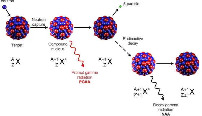
The target nucleus collides with a neutron resulting in a product isotope, in this process the mass number increases by one. The product will instantaneously de-excite into a more stable configuration through the emission of the prompt gamma-rays. In most cases, the compound nucleus is also unstable and decays through the emission of a beta particle with a distinctive half-life. Prompt gamma-rays can be measured to determine elements such as H, B, C, N, P, S, Cd and specifically Sm and Gd. Most of the light elements cannot be determined with NAA, therefore prompt gamma neutron activation analysis (PGNAA) can be complementary method. These processes are shown in Figure 2-1.
Figure 2-1 Scheme for (𝑛, 𝛾), (taken from [22]) The neutron capture for lanthanum as the target nucleus is illustrated as:
𝐿𝑎 57
139 +1𝑛 → 𝐿𝑎 57
140 + (𝑝𝑟𝑜𝑚𝑝𝑡)𝛾 − 𝑟𝑎𝑑𝑖𝑎𝑡𝑖𝑜𝑛 Which also can be presented as below:
𝐿𝑎 57
139 (𝑛, 𝛾) 𝐿𝑎 57 140
By absorbing a neutron, 139La is converted to 140La with emission of a prompt gamma. 140La is an unstable nuclide with a half-life of 40.27 h which emits a beta and transforms to 140Ce. Figure 2-2 elaborates the decay process of 140 La to 140Ce.
Figure 2-2 Decay process of radioactive 140La to stable 140Ce, (taken from [23])
2.1.3.1 Neutron cross section
The probability of a neutron undergoing a nuclear reaction with a nucleus is dependent on the energy of the neutron. This probability is referred to as a neutron cross section. The larger the cross section, the more probable it is that the neutron will have a reaction with the nucleus. The standard unit for measuring the cross section is the barn (b) = 10-24 cm2.
2.1.3.2 Reactor neutron spectrum
Neutrons are classified according to their kinetic energy as follows: 2.1.3.2.1 Thermal neutrons (0.025 eV – 0.55 eV)
Neutrons in thermal equilibrium with a surrounding medium are called thermal neutrons. Applying the relation E = kB × T, (kB is Boltzmann’s constant= 8.617 × 10⁻⁵ eV K-1), we can
calculate that the most probable energy at 300 K corresponds to an energy of 0.026 eV. Thermal neutrons constitute the most important part of the neutron spectrum in thermal reactors [23]. 2.1.3.2.2 Epithermal neutrons (0.55 eV-100 eV)
Fast neutrons that are slowed down by a collision with the surrounding material are called epithermal neutrons.
2.1.3.2.3 Fast neutrons (100 keV-25 MeV)
Neutrons with kinetic energy greater than 1 MeV are called fast or fission neutrons. The main source of these neutrons are nuclear fission reactions. The mean energy for these neutrons are 2 MeV (235U fission). The fission neutrons are thermalized inside the reactor through neutron moderation [22].
In most of the cases, the cross section has a 1/v behaviour in the thermal region and has resonances in the epithermal region. The 1/v behaviour in the thermal regions leads to an activation independent of the neutron temperature and neutron density energy distribution. Normally the 1/v cross section can be described as 𝜎(𝑣) = 𝜎(𝑣0) 𝑣0/𝑣 where 𝑣0 is 2200 m s-1 which is the velocity of neutrons at a temperature of 293.59 K. The non 1/v nuclides show resonance in the thermal region [24].
Neutron cross section (𝜎) dependence on the neutron energy for 103Rh is elaborated in Figure 2-3. For thermal neutrons, 𝜎 decreases approximately as a function of 1/v. The epithermal range is characterized by a resonances defined as “the sharp increases in 𝜎 at well-defined energies which is related to resonances, the formation of a compound nucleus in discrete excited states”[23]. 103Rh has a sharp resonance at energy of 1.26 eV.
Figure 2-3 Relation between the neutron cross section and neutron energy for 103Rh (n, γ), (taken from [1])
2.1.3.3 Neutron flux
The amount of neutrons available for irradiation in the nuclear reactor is described by the neutron flux. In other words, the neutron flux is the number of incident neutrons per square centimeter per second, and cm-2 sec-1 is the unit used for measuring the neutron flux. The neutron energy spectrum in the nuclear reactor can be represented as follows [25]:
𝜑(𝐸) = 𝜑𝑓(𝐸) + 𝜑𝑒(𝐸) + 𝜑𝑡ℎ(𝐸) (2-1)
= 0.484 Φ𝑓𝑒−𝐸sinh (√2. 𝐸) (E>10 keV) (2-2)
+Φ𝑒(𝐸) 𝐸1+𝛼 [(1 − exp (− 𝐸2 𝐸𝑐2)) exp (− 𝐸 𝐸𝑑)] (0.1 eV<E< 100 keV) (2-3) +Φ𝑡ℎ 𝐸 𝐸02exp (− 𝐸 𝐸0 ) (E<1 eV) (2-4)
Where
𝜑𝑓 , Φ𝑓 fast neutron flux per unit energy, total fast neutron flux
𝜑𝑒, Φ𝑒 epithermal neutron flux per unit energy, total epithermal neutron flux 𝜑𝑡ℎ, Φ𝑡ℎ thermal neutron flux per unit energy, total thermal neutron flux 𝐸𝑐=0.1 eV, 𝐸𝑑=300 keV and 𝐸0 = 𝑘 𝑇𝑛 (=0.0253 eV at 20°C) [25].
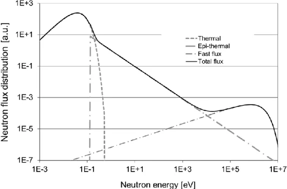
The fission process in the reactor produces fast neutrons and the energy distribution for these neutrons can be presented by the Watt distribution in equation (2-2). Moreover, the behavior of thermal neutrons is described by the Maxwell-Boltzmann distribution in equation (2-4). In the presence of moderators, the fast neutrons can be slowed down to the epithermal region. Equation (2-3) describes the behaviour of the epithermal neutrons [25]. The α in the term 1 𝐸⁄ 1+𝛼 shows how much the epithermal fluence rate deviates from the 1/E behaviour in real irradiation sites. Closer to the core of the reactor, the number of epithermal neutrons are higher compared to thermal neutrons. Also, the spectrum is closer to the 1/E form (α closer to zero) and as one gets farther away from the core, the epithermal flux deviates from its 1/E behaviour. In order to illustrate these features, a typical distribution of the neutron flux in a nuclear reactor is presented in Figure 2-4.
Thermal neutron activation analysis requires at least a minimum neutron flux of 109 cm-2 sec-1. As indicated in Figure 2-4, the highest flux component is related to thermal neutrons. Epithermal and fast neutrons are dependent on the active core of the reactor and also on the effectiveness of the moderator.
Figure 2-4 Schematic representation of a typical neutron flux spectrum in a nuclear fission
reactor, (taken from [24])
2.1.3.4 Activation
The number of nuclide decaying per unit of time is called activity (A). The probability for a nucleus to decay per unit of time is referred to decay constant (𝜆). Therefore, the activity can be expressed as
𝐴 = 𝑁𝜆 (2-5)
Reaction rate (R) of neutron capture reaction is defined by the following:
𝑅 = ∫ 𝑛(𝑣). 𝑣. 𝜎(𝑣). 𝑑𝑣 ∞
0
(2-6)
Where
𝑛(𝑣) neutron density per unit of velocity at neutron velocity v 𝜎(𝑣) cross section
Production of radioactive nuclei can be described by equation (2-7). 𝑑𝑁
𝑑𝑡 = 𝑅. 𝑁0− 𝜆. 𝑁 (2-7)
Where
N0 number of target nuclei
N number of radioactive nuclei 𝜆 decay constant in s-1
For an irradiation time of ti, the disintegration rate of the produced radionuclide can be calculated from the following equation:
𝐴(𝑡𝑖) = 𝑁(𝑡𝑖)𝜆 = 𝑁0𝑅(1 − 𝑒−𝜆𝑡𝑖𝑟) (2-8) The activation cross section and neutron flux density are dependent on the neutron energy. By dividing the neutron spectrum into thermal and epithermal components in equation (2-6), we can obtain: 𝑅 = ∫ 𝑛(𝑣). 𝑣. 𝜎(𝑣)𝑑𝑣 𝑣𝐶𝑑 0 + ∫ 𝑛(𝑣). 𝑣. 𝜎(𝑣)𝑑𝑣 ∞ 𝑣𝑐𝑑 (2-9)
This approach is known as Høgdahl convention.
The division is made at the Cd cut off energy. 113Cd specific absorption cross-section is significant for neutrons with kinetic energies less than 0.55 eV, also referred to as cadmium cut-off energy. Consequently cadmium is widely used as thermal neutron filters [25].
The thermal part can be calculated directly
∫ 𝑛(𝑣) 𝑣 𝜎(𝑣)𝑑𝑣 𝑣𝐶𝑑 0 = 𝑣0 𝜎0∫ 𝑛(𝑣)𝑑𝑣 = 𝑣0 𝜎0𝑛 ∞ 0 (2-10) Where 𝑛 = ∫ 𝑛(𝑣)𝑑𝑣0∞
The epithermal portion can be transformed more conveniently when integrating according to energy. So the infinite dilution resonance integral, I0 can be calculated as
∫ 𝑛(𝑣) 𝑑𝑣 = ∅𝑒∫ 𝜎(𝐸)𝑑𝐸 𝐸 𝐸𝑚𝑎𝑥 𝐸𝐶𝑑 ∞ 𝑣𝑐𝑑 = ∅𝑒 𝐼0 (2-11)
It can be seen from the definition of I0 that the epithermal neutron flux density is proportional to
1/E.
As explained in section 2.1.3.3, in real reactors a new parameter is needed to describe the epithermal neutron density. This parameter can be measured and is introduced by:
𝐼0(𝛼) = ∫ 𝜎(𝐸)𝑑𝐸 𝐸1+𝛼 𝐸𝑚𝑎𝑥
𝐸𝐶𝑑
(2-12)
The reaction rate can be rewritten as:
𝑅 = ∅𝑡ℎ 𝜎0+ ∅𝑒 𝐼0(𝛼) (2-13)
After applying the correction on self-shielding, we obtain:
𝑅 = 𝐺𝑡ℎ ∅𝑡ℎ 𝜎0+ 𝐺𝑒 ∅𝑒 𝐼0(𝛼) (2-14) The ratio of the thermal and epithermal neutron fluxes can be expressed as f:
𝑓 =∅𝑡ℎ ∅𝑒
(2-15)
Also Q0 is referred to as the epithermal to thermal cross section
𝑄0(𝛼) =𝐼0(𝛼)
𝜎0 (2-16)
𝜎𝑒𝑓= 𝜎0(1 +𝑄0(𝛼)
𝑓 ) (2-17)
So equation (2-13) simplifies to 𝑅 = ∅𝑡ℎ𝜎𝑒𝑓.
Nuclear transformations are represented by measuring the number of nuclear decays. That being said, the number of activated nuclei present at the start of the measurement can be calculated from equation (2-18)
𝑁(𝑡𝑖𝑟, 𝑡𝑑) =𝑅𝑁0
𝜆 (1 − 𝑒
−𝜆.𝑡𝑖𝑟)𝑒−𝜆.𝑡𝑑 (2-18)
Where 𝑡𝑖𝑟, 𝑡𝑑 are the irradiation and decay time, respectively. Moreover, the number of nuclides disintegrating during the measurement can be calculated through equation (2-19).
𝑁(𝑡𝑖𝑟, 𝑡𝑑, 𝑡𝑚) = 𝑅𝑁0(1 − 𝑒−𝜆𝑡𝑖𝑟)𝑒−𝜆.𝑡𝑑
(1 − 𝑒𝜆𝑡𝑚)
𝜆𝑡𝑚 = 𝑅𝑁0𝑆𝐷𝐶 (2-19)
Therefore, by measuring the emitted gamma-rays and considering the half-life, the radio nuclides can be identified and quantified. By introducing (𝜃), the isotopic abundance and mass of the sample, w, the parameter N0 can be rewritten as (𝑁𝐴𝑣𝜃
𝑤 𝑀)
By using 𝑅 = ∅𝑡ℎ𝜎𝑒𝑓 as the reaction rate and considering the coincidence correction factor COI in net peak area, the activation equation can be written as:
𝑁𝑝
𝐶𝑂𝐼 = Δ𝑁𝛾𝜀 = 𝑅 𝑁𝐴𝜃𝑤
𝑀 𝑆𝐷𝐶𝛾𝜀 (2-20)
Where Np is number of counts in the full-energy peak when taking to account pulse losses.
As for the (𝑛, 𝛾) reaction, the reaction rate can be represented using the number of impulses in a given peak by 𝑅 = 𝑀𝑁𝑝 𝑆𝐷𝐶 𝐶𝑂𝐼 𝑤𝑡𝑚 𝑁𝐴𝜃𝜀𝛾 (2-21)
As for the epithermal neutrons, the reaction can be introduced as: 𝑅𝑒 = 𝑀 (𝑆𝐷𝐶 𝐶𝑂𝐼 𝑤𝑡𝑁𝑝 𝑚)𝐶𝑑 𝑁𝐴𝜃𝜀𝛾 (2-22)
If we define the specific activity as: 𝐴𝑠𝑝 = 𝑁𝑝⁄𝛾𝜀 𝐶𝑂𝐼. Reaction rate for thermal neutrons can be rewritten as
𝐴𝑠𝑝 = 𝑁𝑝
𝑆𝐷𝐶 𝐶𝑂𝐼 𝑤𝑡𝑚 (2-23)
By combing equation (2-23) and equation (2-14), one finds:
𝐴𝑠𝑝 =𝑁𝐴𝜃𝛾
𝑀 [𝐺𝑡ℎ 𝜙𝑡ℎ 𝜎0+ 𝐺𝑒 𝜙𝑒 𝐼0(𝛼)]𝜀 (2-24)
2.2 Methods of standardization
So the concentration of the nuclide can be derived from the following equation:
𝑐𝑎 = 𝑀𝑎𝑤𝑎 𝑁𝐴 𝜃𝑎 𝛾𝑎 𝑤. (𝑆𝐷𝐶 𝐶𝑂𝐼 𝑡𝑁𝑝 𝑚)𝑎 [𝐺𝑡ℎ 𝜙𝑡ℎ 𝜎0,𝑎+ 𝐺𝑒,𝑎𝜙𝑒𝐼0,𝑎(𝛼)]𝜀𝑎 × 106𝑚𝑔 𝑘𝑔−1 (2-25)
There are three types of standardization: absolute, relative and comparator standardization methods. In this context, the use of word ‘standardization’ refers to ‘calibration of NAA’, which consists in finding the relation between the concentration of the analyte and the intensity of the related peak [25]. A review was completed regarding the features and drawbacks of these three methods [26].
2.2.1 Absolute standardization
In this method, the calculation of the concentration is feasible according to the form described in equation (2-25). Also, equation (2-25) can be used when the burn-up effect can be neglected and nuclear values related to the reactor (𝛼, 𝑓, 𝜙𝑡ℎ) are staying constant otherwise it is vital to monitor
the stability of these parameters during the irradiation. In this case, equation (2-25) will be transformed to: 𝑐𝑎 = (𝑆𝐷𝐶 𝐶𝑂𝐼 𝑤𝑡𝑁𝑝 𝑚) 𝑤𝐴𝑠𝑝,𝑚 .𝑀𝑎𝜃𝑚𝛾𝑚𝜎0,𝑚 𝑀𝑚𝜃𝑎𝛾𝑎𝜎0,𝑎 .𝐺𝑡ℎ,𝑚𝑓 + 𝐺𝑒,𝑚𝑄0,𝑚(𝛼) 𝐺𝑡ℎ,𝑎𝑓 + 𝐺𝑒,𝑚𝑄0,𝑎(𝛼) .𝜀𝑚 𝜀𝑎 . 106𝑚𝑔 𝑘𝑔−1 (2-26)
Although this approach is experimentally simple, the accurate knowledge of nuclear parameters is necessary. Poor knowledge of accurate values can be a source of systematic error up to 20% [25, 27]. In addition, the need for accurate neutron distribution characteristics, accurate detector efficiency and neutron self-shielding factors are also required.
2.2.2 Relative method of standardization
In this method, a chemical standard with a known mass of ws of an element to be determined
needs to be irradiated along with the sample. Both of the samples should be irradiated in the same geometrical conditions with respect to the detector. Since 𝑆𝑎 = 𝑆𝑠, 𝑀𝑎 = 𝑀𝑠, 𝛾𝑎 = 𝛾𝑠, 𝜎0,𝑎 = 𝜎0,𝑠, 𝐼0,𝑎 = 𝐼0,𝑠, 𝑎𝑛𝑑 𝜃𝑎 = 𝜃𝑠 equation (2-25) can be rewritten for the standard and the sample and combined into equation (2-27):
𝑐𝑎 = (𝐷𝐶𝑤𝑡𝑁𝑝 𝑚)𝑎 (𝐷𝐶𝑤𝑡𝑁𝑝 𝑚)𝑠 . 𝐺𝑡ℎ,𝑠𝑓 + 𝐺𝑒,𝑠𝑄0,𝑠(𝛼) 𝐺𝑡ℎ,𝑎𝑓 + 𝐺𝑒,𝑎𝑄0,𝑎(𝛼). 𝜀𝑠 𝜀𝑎. 10 6𝑚𝑔. 𝑘𝑔−1 (2-27)
It is assumed that the neutron flux for sample and the standard is constant. The detection efficiency and gamma attenuation in the sample and standard should be taken into account. For multielement analysis, this technique has several disadvantages:
The preparation of standards can be time consuming
In some situations the detection of element is not possible if the standards for that element is not available
Homemade multi-element standards need to be prepared with a high chemical stability for the components and with high homogeneity
It should be noted that the certified reference materials (CRM) and commercial multielemental reference materials should be used only for quality control purposes since the uncertainty of the elements’ concentrations is usually higher than in-house standards. In addition, CRMs are costly and are available in limited quantities [27, 28].
2.2.3 Comparator method of standardization
The single-comparator standardization method applies k-factors. These values are determined experimentally by co-irradiating the standard with a single comparator together.
𝑘𝑐(𝑠) =𝐴𝑠𝑝,𝑠
𝐴𝑠𝑝,𝑐 (2-28)
kc(s) in equation (2-28) is defined as:
𝑘𝑐(𝑠) = 𝑀𝑐. 𝜃𝑠𝛾𝑠𝜎0,𝑠 𝑀𝑠. 𝜃𝑐𝛾𝑐𝜎0,𝑐 .𝐺𝑡ℎ,𝑠. 𝑓 + 𝐺𝑒,𝑠. 𝑄0,𝑠(𝛼) 𝐺𝑡ℎ,𝑐. 𝑓 + 𝐺𝑒,𝑐. 𝑄0,𝑐(𝛼) .𝜀𝑠 𝜀𝑐 (2-29)
If the following conditions are met, the concentration can be calculated from equation (2-30), thus:
There should be no significant deviation between the irradiation conditions (f, α) in the case of the analysis and the determination of kc(s)
𝜃𝑎 = 𝜃𝑠
Neutron self-shielding should also be similar in both analyte-comparator and standard-comparator, the best case is to make Gth=Ge=1 in order to find:
𝑐𝑎 = (𝑆. 𝐷. 𝐶. 𝑤. 𝑡𝑁𝑝 𝑚)𝑎 𝐴𝑠𝑝,𝑐 . 10 6 𝑘𝑐(𝑠) 𝑚𝑔. 𝑘𝑔−1 (2-30)
This method offers the same advantages as the absolute method while there is no flux deviation problem. Moreover, by determining precisely the k factors values, the flux ratio, and the counting efficiency, the total uncertainty of the measurements can be reduced.
On the other hand, selecting suitable comparator elements for a multi-element analysis can be challenging. Since calibrating the analysis calculations based on all sample-detector geometry positions, corrections of coincidence summing and attenuation can be tedious [27].
2.2.4 k
0-method of standardization
If the k-factors in single-comparator method are normalized based on the experimental conditions such as (f,α) for the irradiation stage, (𝜀) for the counting stage, the following equation will be obtained: 𝑘0,𝑐(𝑠) = 𝑘𝑐(𝑠). 𝐺𝑡ℎ,𝑐𝑓 + 𝐺𝑒,𝑐𝑄0,𝑐(𝛼) 𝐺𝑡ℎ,𝑠𝑓 + 𝐺𝑒,𝑠𝑄0,𝑠(𝛼). 𝜀𝑝,𝑐 𝜀𝑝,𝑠 (2-31) =𝐴𝑠𝑝,𝑠 𝐴𝑠𝑝,𝑐. 𝐺𝑡ℎ,𝑐𝑓 + 𝐺𝑒,𝑐𝑄0,𝑐(𝛼) 𝐺𝑡ℎ,𝑠𝑓 + 𝐺𝑒,𝑠𝑄0,𝑠(𝛼). 𝜀𝑝,𝑐 𝜀𝑝,𝑠 (2-32)
So the k0-factors can be defined as a nuclear constant: 𝑘0,𝑐(𝑠) =𝑀𝑐. 𝜃𝑠. 𝜎0,𝑠. 𝛾𝑠
𝑀𝑠. 𝜃𝑐. 𝜎0,𝑐. 𝛾𝑐 (2-33)
These values are measured experimentally and published in the literature [29-33]. If the samples are coirradiated with the monitor, where the k0,c(m)-factors are available, we have:
𝑘0,𝑐(𝑠) 𝑘0,𝑐(𝑚)
= 𝑘0,𝑚(𝑠) (2-34)
So the analyte concentration can be obtained as
𝑐𝑎 = (𝑆𝐷𝐶 𝐶𝑂𝐼 𝑤𝑡𝑁𝑝 𝑚) 𝐴𝑠𝑝,𝑚 . 𝑘0,𝑐(𝑚) 𝑘0,𝑐(𝑎) . 𝐺𝑡ℎ,𝑚𝑓 + 𝐺𝑒,𝑚𝑄0,𝑚(𝛼) 𝐺𝑡ℎ,𝑎𝑓 + 𝐺𝑒,𝑎𝑄0,𝑎(𝛼) . 𝜀𝑚 𝜀𝑎 . 10 6𝑚𝑔 𝑘𝑔−1 (2-35)
As explained before, all these equations are written in the Høgdahl convention (modified for 1/E1+α). In this formalism, it is considered that the cross section for all the nuclides follows a 1/v behaviour. While this is true for most of the nuclides, there are some exceptions where the deviation is significant: 151Eu(n,γ)152mEu, 151Eu(n,γ)152Eu, 168Yb(n,γ)169Yb, and 176Lu(n,γ)177Lu.
In these few cases, the Westcott formalism [34] is applicable and the [f+Q0,m(α)]/[f+Q0,a(α)] ratio
in equation (2-24) should be replaced by
𝑔𝐴𝑢(𝑇𝑛) + 𝑟(𝛼)√𝑇𝑛/𝑇0× 𝑠0,𝐴𝑢(𝛼)
𝑔𝑎(𝑇𝑛) + 𝑟(𝛼)√𝑇𝑛/𝑇0× 𝑠0,𝑎(𝛼) (2-36)
Where g(Tn) is the ‘Westcott’s g-factor’ and Tn is the neutron temperature, g(Tn) is a factor used
to describe the deviation from the 1/v behaviour of the thermal radiative cross section, 𝑟(𝛼)√𝑇𝑛/𝑇0 is the spectral index and s0(α) is the epithermal to thermal cross-section ratio
modified for the 1/E1+α epithermal spectrum.
2.3 Equipment
2.3.1 Nuclear reactors
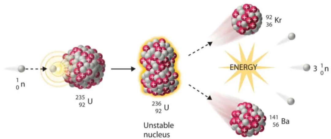
Since 1970, different sources have been used for generating neutrons, namely, accelerators, neutron generators, isotopic neutron sources and nuclear reactors. The most important source of neutrons is the nuclear reactor which is based on the fission process of 235U. Thermal neutrons have high cross section of 586 b for this process. Fission of 235U produces 2 to 3 neutrons together with two large fission fragments. The fission reaction can be expanded by the equation (2-37). 𝑈 92 235 + 𝑛 0 1 → 𝑋 𝑍1 𝐴1 + 𝑌 𝑍2 𝐴2 + 𝑣 𝑛 0 1 (2-37)
Figure 2-5 shows fission process of 235U.
Figure 2-5 Fission reaction (taken from [22])
The 2 to 3 neutrons generated through fission of uranium are fast neutrons which need to be thermalized to start another fission reaction. Therefore they have to be thermalized by the moderator. Moderators are usually light elements like hydrogen, carbon and oxygen. The choice of moderators can affect the thermal and epithermal neutron ratio. In nuclear reactors with light water as a moderator, an epithermal neutron flux can be 20-50 times lower than a thermal neutron flux.
Figure 2-6 Cumulative chain yield for the fission of 235U as a function of mass number (taken from [23])
Figure 2-6 shows the yield of uranium products with respect to the mass number. As interpreted from Figure 2-6, two large segments produced by uranium fission have masses around 90–100 and 133–143. If the sample that needs to be analysed contains uranium, there will be some light rare earth elements in the sample which are produced by 235U fission. This can be a major source of error in NAA when determining rare earth elements in the samples containing 235U [23, 35]. With the decommissioning of the reactors, there are six research reactors currently remaining in Canada. Research reactors are much smaller than the reactors used in a nuclear power plants. They have been used for research, analytical purposes and production of radioactive substances for medical and industrial uses [36].
2.3.2 The counting system
The gamma-spectroscopy system used is composed of high-purity germanium (HPGe) detectors and pulse-processing electronics. The electronic system consists of a high voltage power supply, amplifier, analogue to digital converter (ADC) and Multi-Channel Analyzer (MCA). Their role can be summarized by collecting the electrons produced by the incident gamma-rays and sorting them by energy. This procedure can be summarized as follows [23, 37]:
The gamma photons interact with the detector crystal which leads to the production of electrons
Voltage is applied to sweep electrons from the crystal Electrons produced make a current which forms signal pulse Preamplifier is required to increase the pulse size
The amplifiers are used to boost the signal registered in the detector in order to reach a high signal-to-noise ratio
ADC is used to convert signal intensity to numerical value to be sent to MCA MCA sorts the signals as a function of their energy
The evaluation of the spectra is done by the analyst with a software
2.3.3 Detectors
One of the most important parameters that represents a characteristic of a detector is efficiency. Absolute efficiency can be defined as the observed counts in the detector per unit of time divided by the absolute photon rate emitted by the source. Efficiency depends on sample-detector geometry and the distance between the sample and the detector.
Another concept used in the detection efficiency is relative efficiency which is defined as the relative photopeak efficiency of a detector compared to that of a 3 in. × 3 in. NaI (Tl) detector at an energy of 1333 keV (60Co) and a distance of 25 cm between source and detector.
The relative efficiency increases with the volume of the detector. On the other hand, efficiency decreases with a gamma energy proportional to E-0.5 and at energies above about 300 keV. A
typical germanium detector has a maximum efficiency at 100 keV and decreases by about one order of magnitude at 1333 keV.
Another characteristic of the detectors is its resolution defined as its ability to separate the closely spaced peaks. It is reported as FWHM (full width at half maximum) which is the width of a peak at half of its maximum intensity. For planar Ge detectors resolution is reported for the 121.8 keV peak of 152Eu or the 122.1 keV γ-peak of 57Co. For large HPGe detectors, resolution is usually specified for the 1333 keV line of 60Co. Planar Ge detector is better choice for detecting gamma energies below ≈150 keV because ‘high-energy gamma rays are much less likely to be absorbed in a planar detector than in a high-volume Ge detector’ so the Compton background is reduced [23, 35].
2.3.3.1 Interaction of electromagnetic radiation with matter
The absorption of gamma-rays or X-rays by matter follows equation (2-38)
𝐼 = 𝐼0× exp (−𝜇𝑑) (2-38)
Where I0 is the intensity of the photon before travelling through a distance of d (cm) in the matter.
The 𝜇 (𝑐𝑚)is the absorption coefficient which is the sum of three effects including the photoelectric effect, the Compton effect and the pair-production effect.
2.3.3.1.1 Photoelectric effect
In the photoelectric effect, total energy of the photon is transferred to an electron’s orbital and in about 80 % of cases leads to a K electron and in 20 % to an L electron. The energy of the electron emitted will be the energy of the photon minus the binding energy of that electron. Immediately, the gap is filled with an electron from the next higher shell, and a characteristic X-ray is emitted accordingly.
2.3.3.1.2 Compton effect
The Compton effect is the result of an elastic scattering between a gamma-ray and an electron, which creates an energetic recoil electron and a scattered gamma-ray photon. Only part of the energy of the photon is transferred to the electron which is dependent on the scattering angle [38].
The scattered photon may be absorbed by the photoelectric effect, undergo more Compton effect or escape from the detector. In case the energy of the photon is absorbed by the detector, it contributes to the Compton continuum, which referred to a region with an undesired high background in a gamma spectrum. As for 60Co with a gamma energy of 1333 keV, by calculating the energy of the electron we get the value of 1119 keV which is called Compton edge, illustrated in Figure 2-7.
Figure 2-7 Compton effect for NaI detector vs. Ge(Li) detector, (taken from [23])
2.3.3.1.3 Pair-production effect
When the photon is in the strong electromagnetic field near the nuclei of the absorbing material, it may interact with an absorber nucleus and produce an electron-positron pair. This refers to a pair production effect and it occurs at very high energies. The minimum energy of a gamma that can cause pair production is equal to the sum of the rest masses of the electron and positron which is 1022 keV (511 keV each). The remaining part of the energy of the incident photon will turn into a kinetic energy for an electron and positron. When the positron has lost this energy, it annihilates by reacting with another electron and consequently generating two 511 keV γ-rays [23]. These gamma energies can be absorbed to the detector or undergo Compton effect [23, 38].
CHAPTER 3
SPECIFIC OBJECTIVES AND METHODOLOGICAL
ASPECTS
Neutron activation analysis has been used for the determination of rare earth elements in geological samples. With the advent of Ge(Li) detectors in 1963, Gordon et al.[39] were able to determine La, Ce, Sm, Eu, Tb, Tm, Tb and Lu in standard rock samples but with cooling times up to a few months. In 1978, Duffield et al. [40] applied a radiochemical separation after the irradiation in order to obtain the concentration of rare earth elements in the rocks. They were able to determine all the 14 rare earth elements with a shorter cooling time of 12 days.
Many studies have been done to determine the REE distribution in rocks, sediments, meteorites using NAA [11, 41-44]. Danko et al. [45] have conducted a study on REE content in biological materials by NAA with pre- and post-irradiation separation. They were able to assess the concentration of 13 REE (excluding Gd) in 4 weeks.
Several studies have been done in order to assess the REE content with k0-NAA [15-18].
Ravisankar et al. [16] determined the La, Ce, Sm, Eu, Tb, Yb content in beach rock samples with a longer cooling time of 30-50 days. Silachyov et al. [46] compared internal standard method and single comparator method for determining rare earth elements in rock samples. They were able to measure La, Ce, Nd, Sm, Eu, Tb, Yb, Lu with decay time of 7 days and 30 days. Xiao et al. [18] investigated the uranium fission interference on the measurement of Nd, Ce and La and were able to determine La, Ce, Nd, Sm, Eu, Tb, Yb and Lu in ore reference material.
The accurate analysis of REEs in mineral matrices with high contents of REEs in short turnaround times poses several challenges in terms of analytical aspects which can lead to systematic error or uncertainty in the measurements. In the previous works, this has been avoided by radiochemical separation or long cooling times. In this study we have investigated the possible sources that can bring systematic error to the analysis, with the aim of reducing the turnaround time while conserving the accuracy.
3.1 Sources of error
First objective of this study is to verify the validity and the efficiency of the libraries used at Polytechnique Montreal for determination of rare earth elements.
3.1.1 Nuclear data, detection efficiency
Ecole Polytechnique Activation Analysis (EPAA) software is used as part of the k0-NAA analysis
at SLOWPOKE laboratory. The libraries associated with this software are generated based on the k0 method and detection efficiency model which can be summarized in the sensitivity factors (B) [47]. 𝐵 =𝑁𝐴𝑣𝜃𝐴𝑢𝜎0,𝐴𝑢𝐼𝐴𝑢 𝑀𝐴𝑢 𝑘0(1 + 𝑄0(𝛼) 𝑓 )𝜀 (3-1) Where NA Avogadro number 𝜃𝐴𝑢 Au isotopic abundance
𝜎0,𝐴𝑢 Au radiative cross section at 2200 m.s-1 𝐼𝐴𝑢 Au 411.8 keV gamma-ray intensity 𝑀𝐴𝑢 Au atomic mass
𝑄0(𝛼) resonance integral (1/E1+α) to 2200 m.s-1 cross-section ratio f ratio of thermal to epithermal flux
ε peak relative detection efficiency
The accuracy of k0-NAA depends on the method’s core parameters which are k0 and Q0 factors. Since introducing the first generation of k0 values [28, 48-51], each decade an updated version is published but there are still some values that have not been re-determined since 30 years ago. There have been several studies at Polytechnique Montreal in order to verify these values [32, 33] yet not all of the rare earth elements are among the re-measured values.
Along with the k0 standardization method, the efficiency model is included in the library data, thus:
𝜀 = 𝜀250𝑚𝑚 𝜀𝑑
Where
𝜀250𝑚𝑚 Efficiency curve evaluated at 250 mm from the detector 𝜀𝑑 Efficiency at distance d
𝑓𝑠𝑎𝑚𝑝𝑙𝑒𝑠𝑖𝑧𝑒 Correction for sample size
𝑎𝑡𝑎𝑏𝑠𝑜𝑟𝑏𝑒𝑟𝑠 Correction for gamma-ray attenuation in absorbers 𝑎𝑡𝑠𝑎𝑚𝑝𝑙𝑒 Correction for gamma-ray attenuation in sample 𝐶𝑂𝐼 Coincidence summing correction factor
COI in the detection efficiency refers to the correction factor for true-coincidence summing. Gamma-rays detected by the detector are usually part of a cascading photons produced in deexcitation processes of an unstable nuclei so they are accompanied by other gamma-rays. By increasing the efficiency of detectors, the simultaneous detection of two photons belonging to the same decay process becomes more probable. If the lifetime of the intermediate levels in the nuclear decay are shorter than the resolving time of the spectrometer, it cannot differentiate between both peaks and the response in the detector would give the same result for the combined peaks of a single pulse. That being said, the total count rate is not affected by the true-coincidence summing [25].
True-coincidence summing has to be taken into account especially when the sample is counted close to the detector.
3.1.2 Interferences
3.1.2.1 Spectral interferences
When analysing a specific energy for each radio nuclide, one can be interfered by gamma-rays emitted by other radio-nuclides. The interfering gamma-rays can be close to each other in terms of energy or even completely overlapped. By using a high resolution germanium detector, some of these interferences can be reduced. In other cases this is corrected by analyzing another peak of the interfering nuclide. By knowing the ratio between the intensity of the peaks we will be able to subtract them from the peak area of the radio-nuclide of interest. For some of these
interferences, corrections are considered in the library for only some of the counting positions. Therefore it is necessary to measure these factors for possible interferences in all counting positions.
This kind of interference is significant especially when both radio-nuclides have similar half-lives or the concentration of the interfering nuclide is high enough to affect the results of the element of interest.
3.1.2.2 Uranium fission interference
Uranium fission interferences are considered as part of nuclear interferences. As explained in the nuclear reactor section, some elements can be produced from fission of 235U such as 140La, 141Ce, 153Sm or 147Nd. If the uranium concentration is in the same range or higher than the concentration of the target radio-nuclide, correction for this interference is necessary. This is dependent on the fission yield, activation cross section and isotopic abundance of the target radio-nuclide. The interference can be calculated roughly from equation (3-3) [52], that is:
𝐼𝑛𝑡 = 4.18𝑦𝑖𝑀𝑥
238.03𝜃𝜎(𝑛, 𝛾) (3-3)
Where
𝑦𝑖 fission yield of the radio-nuclide 𝑀𝑥 atomic weight of target element
𝜃 isotopic abundance of the target element
These factors are included in EPAA’s libraries. Measurements were done to determine new correction factors.
3.1.2.3 Neutron self-shielding
During the irradiation, the neutron flux can be perturbed inside the sample. Self-moderation and neutron self-shielding are among the main causes of the neutron flux deviations [25].
Self-moderation: Neutrons can reduce their energy by collision with atoms. By scattering on the
light atoms, fast and epithermal neutrons can be thermalized. This phenomenon is more probable in the presence of hydrogen [25].
Neutron self-shielding: A considerable decrease in the neutron flux is observed due to the
absorption of neutrons undergoing a neutron capture reaction. If the samples contain high concentrations of elements that strongly absorb thermal neutrons, the inner layers of the sample will see a lower neutron flux. This flux depression is referred to as neutron self-shielding [25, 53, 54]. As an example, mean absorption cross sections for naturally occurring samarium, europium, gadolinium, and dysprosium are 5600, 4300, 49000, and 1100 barns, respectively, indicating that these elements are subject to the neutron self-shielding effect. This phenomenon can also occur for epithermal neutrons in case of elements with strong resonances of the absorption cross section in the epithermal region.
Case et al.[55] , Dwork [56] and Nisle [57] proposed the first algorithms for neutron self-shielding correction mainly focusing on thermal neutrons. Later on, Stewart and Zweifel derived an expression in which they assume that the neutron flux is isotropic [53, 58]. Algorithms were compiled by Gilat et al. [59], Flemming [60] and integrated in k0-standardazation by De Corte.
To correct the self-shielding effect in a cylindrical sample with an unknown composition, Chilian et al. [54] introduced a new iterative approach. They proposed equation (3-4) for correcting thermal and epithermal self-shielding.
0.06 + M h r r k N m + 1 0.94 Q f Q M m h r r k N + 1 1.00 Q f f = G at ep abs ep Av 2 0.8 i ati i abs i th Av eff
( ) ( ) ) ( ) ( ) ( , 0 0 964 . 0 , , 0 (3-4) Wheremi mass of element i in the sample
NA Avogadro’s number
r, h radius and height of the sample
kth, kep thermal and epithermal self-shieling constants
𝜎𝑎𝑏𝑠,𝑖 thermal neutron absorption cross section for element i 𝜎𝑎𝑏𝑠,𝑒𝑝 epithermal neutron absorption cross section
Mat,i atomic mass of element i 3.1.2.4 Gamma ray self-attenuation
Not all the gamma rays that are emitted by the sample reach the detector. A fraction of photons is absorbed or scattered by the material itself and cannot contribute to the peak count-rate. This fraction can cause a considerable error in the analysis especially when dealing with low energy gamma-rays in samples containing heavy elements. This phenomena is referred to as gamma ray self-attenuation and affects the quantification of isotopes such as 141Ce, 147Nd, 153Sm, 165Dy and 166Ho with low energy gamma-rays. Gamma ray self-attenuation effect will increase since the attenuation is a function of energy and the atomic number.
Self-attenuation is dependent on a number of factors such as the sample geometry and the linear attenuation coefficient. The linear attenuation coefficient (𝜇𝑥) is a function of the sample’s composition, material density and photon energy. For gamma-rays with an intensity of I0, passing
through a length of x in the material, the emerging radiation transmitted by the sample can be expressed as the Beer-Lambert law which is presented in equation (3-5) [61-63]:
![Figure 1-1 The lanthanide contraction (taken from [5])](https://thumb-eu.123doks.com/thumbv2/123doknet/2322276.29349/20.918.213.709.231.534/figure-the-lanthanide-contraction-taken-from.webp)
![Table 1-1 Selected end-uses of rare earth elements, (adapted from [8])](https://thumb-eu.123doks.com/thumbv2/123doknet/2322276.29349/21.918.95.821.177.964/table-selected-end-uses-rare-earth-elements-adapted.webp)
![Figure 2-2 Decay process of radioactive 140 La to stable 140 Ce, (taken from [23])](https://thumb-eu.123doks.com/thumbv2/123doknet/2322276.29349/28.918.228.731.223.776/figure-decay-process-radioactive-la-stable-ce-taken.webp)
![Figure 2-3 Relation between the neutron cross section and neutron energy for 103 Rh (n, γ), (taken from [1])](https://thumb-eu.123doks.com/thumbv2/123doknet/2322276.29349/30.918.173.750.129.534/figure-relation-neutron-cross-section-neutron-energy-taken.webp)
![Figure 2-6 Cumulative chain yield for the fission of 235 U as a function of mass number (taken from [23])](https://thumb-eu.123doks.com/thumbv2/123doknet/2322276.29349/42.918.209.703.130.543/figure-cumulative-chain-yield-fission-function-number-taken.webp)
![Figure 2-7 Compton effect for NaI detector vs. Ge(Li) detector, (taken from [23])](https://thumb-eu.123doks.com/thumbv2/123doknet/2322276.29349/45.918.165.751.334.673/figure-compton-effect-nai-detector-ge-detector-taken.webp)
![Figure 3-1 Gamma-ray attenuation (adapted from [64])](https://thumb-eu.123doks.com/thumbv2/123doknet/2322276.29349/52.918.217.725.122.494/figure-gamma-ray-attenuation-adapted-from.webp)
