Any correspondence concerning this service should be sent
to the repository administrator: [email protected]
This is an author’s version published in:
http://oatao.univ-toulouse.fr/22526
Open Archive Toulouse Archive Ouverte
OATAO is an open access repository that collects the work of Toulouse
researchers and makes it freely available over the web where possible
To cite this version:
Ortega Espluga, Lorenzo and Poulliat, Charly and
Boucheret, Marie-Laure and Aubault, Marion and Al Bitar, Hanaa Advanced
co-design of message structure and channel coding scheme to reduce the time
to CED and to improve the resilience for a Galileo 2nd Generation new signal.
(2018) In: ESA Workshop on Satellite Navigation Technologies and European
Workshop on GNSS Signals and Signal Processing (NAVITEC 2018), 5
December 2018 - 7 December 2018 (Noordwijk, Netherlands).
Advanced Co-Design of Message Structure and Channel Coding Scheme to Reduce the Time
to CED and to Improve the Resilience for a Galileo 2nd Generation New Signal
Lorenzo Ortega Espluga(1), Charly Poulliat (2), Marie-Laure Boucheret(2), Marion Aubault (3), Hanaa Al Bitar(4) (1)
TéSA, Toulouse, France ([email protected] )
(2)
INP Toulouse, Toulouse, France
([email protected],[email protected] )
(3)
CNES, Toulouse, France ([email protected] )
(4)
Thales Alenia Space, Toulouse, France ([email protected] )
ABSTRACT
Reducing the Time To First Fix (TTFF) and improving the resilience of future Galileo signals are two important characteristics, especially when considering urban environments. To reach these goals, we studied two new advanced techniques based on the co-design of the message structure and the channel coding scheme. The first technique proposes a reduction of time needed to retrieve the data by reinforcing the parity check matrix structure constraints. The second technique provides an enhancement of the retrieved data error rate in parallel to a reduction of the time needed to retrieve the data thanks to a new co-design requirement based on a family of codes inspired from the rate-compatible root LDPC codes. The results obtained are promising, since the time to retrieve the data (and thus the TTFF) is significantly reduced, while keeping a good level of demodulation performance.
I-INTRODUCTION
Designing a new GNSS signal is always a trade-off between improving performance while keeping a reasonable complexity level of the system. Recent researches [1],[2],[3] have shown the interest of improving the current GNSS system performance in both, the reduction of the Time-To-First-Fix (TTFF) and the enhancement of the resilience of the broadcasted data, in particular the Clock and Ephemeris Data (CED). The advanced scheme for co-designing the message structure along with a structured channel coding proposed throughout this paper can jointly reach these usually conflicting objectives.
In previous works [2], co-designs of message structure and channel coding scheme were already presented in order to reduce the time to retrieve the CED, also called Time-To-Data (TTD), without losing resilience of the CED under low C/N0 environments. In particular, a new message structure based on block fading channel model, along with a so-called
root LDPC codes [4] channel coding scheme was proposed. These ½ rate root LDPC codes provide well desired coding properties such as: Maximum Distance Separable (MDS) [4], and full diversity under the well-known Belief-Propagation (BP) decoding algorithm. Such properties result in reducing the time to retrieve the CED under good channel conditions and enhancing resilience under low C/N0 environments. This scheme is further combined with a
Cyclic Redundancy Check (CRC) in order to provide data integrity [1] [3].
In this paper, two new advanced methods to co-design jointly the message structure and the channel coding scheme are proposed.
The first one consists in reinforcing the design constraints of the root-LDPC parity check matrix structure in order to provide a reduction of the TTD (compared to the previous works based on a co-design message structure with a root-LDPC code channel scheme of rate ½ [2]). This can be achieved by introducing an independent erasure decoding algorithm which reduces the TTD by easing the retrieval of the data to decode the CED.
A second advanced technique is proposed in order to increase the resilience of the signal (in enhancing the CED Error Rate (CEDER) performances) in parallel to the reduction of the TTD. This technique is different from the methodology to co-design the structure of the message and the channel coding scheme proposed in previous works. It rather looks for a channel coding scheme with a coding rate lower than ½. Of course, the fact of decreasing the coding rate could involve an increase of the TTD. Therefore, the new message structure has to be adapted to this new channel coding rate
in order to avoid increasing the TTD. In order to address the new co-design requirements, a family of codes inspired from rate compatible root LDPC codes [8], is considered.
The paper is organized as follows. Section II presents the proposed advanced techniques to reduce the TTD and to enhance the error correction performances. Their performances are presented and analyzed in Section III. Conclusions are finally drawn in Section IV.
II- ADVANCED TECHNIQUES TO CO-DESIGN THE MESSAGE STRUCTURE AND THE CHANNEL CODING SCHEME
First method: reinforce design constraints of the root LDPC parity check matrix
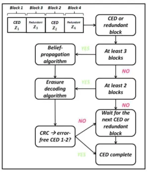
It is proposed here to increase the constraints on the Root-LDPC parity check matrix structure in order to speed up the CED information decoding. To this aim, an independent erasure decoding algorithm is introduced. The new root-LDPC code structure is modeled in n=4 independent blocks of information (2 blocks of systematic CED blocks and 2 data redundant blocks). Thanks to the erasure decoding algorithm, the retrieval of the systematic information is possible once k=2 error free blocks are retrieved, whether the error free block is systematic or redundant. Moreover, since these codes belong to the root-LDPC codes family:
· Firstly, in some cases the retrieval of the systematic information can be directly obtained by running the BP decoding algorithm instead of the erasure decoding algorithm.
· Secondly, the good error correcting performances under low C/N0 environments are kept.
Let’s present the regular root-LDPC parity check matrix [4]:
!= " #$% 0&% #$' 0 (&' (1)
where # represents an identity matrix, $% and $' represent Quasi-Cyclic (QC) matrices [6] of Hamming weight 2 and
&% and &' represents QC matrices of Hamming weight 3. Moreover, subindexes) and * represent respectively the systematic and the redundant information. Following the block fading channel model [4], subindexes1 and 2 represent each of the fading block where the informationwill be sent.
In order to compute the generator matrix (generating the redundant symbols), the parity check submatrix corresponding to the redundant bits must be full rank. Let’s re-structure the parity check matrix by inserting the systematic information in the first columns as it is illustrated in (2).
!= " #$% #$' 0 &'
&% 0 ( = ( - . )
(2)
The parity check matrix shown in (2) can be divided into two submatrices: A and B. Let’s denote 3̅ = [56 *̅] as the codeword generated by the generator matrix, where 56 is the systematic information bits vector and *̅ is the parity bits vector. Since 3̅7 = -567 + .*̅7 = 0, for binary codes we can obtain the parity bits from (3).
*̅7 = (.9%)-567 (3)
As long as B is an invertible matrix, the encoding can be accomplished by using (3) with linear complexity as a function of the length of parity bits. However, there is one main concern to obtain .9%:
· .9% may not be invertible
From the precedent statement, we conclude that B must be full rank in order to have inverse.
In order to reduce the TTD, an independent erasure decoding algorithm is proposed. This algorithm requires an extra constraint in the design of the root-LDPC parity check matrix structure. The extra constraint is provided along with the erasure decoding algorithm in the following subsection.
MDS erasure decoding algorithm:
As it is explained, the Root-LDPC code structure is modeled in n=4 independent blocks of information. Let’s define the receiver blocks of information as :$ with ) ∈ (1,2,3,4), where ) represents the index of the blocks; the transmitted block of information as @$ and the error block as A$ such as :$= @$+ A$ . Let’s calculate the syndromes as:
BC= :%+ $':'+ &':D (4)
B%= $%:%+ :'+ &%:E (5)
The erasure blocks indexes are defined by F and G with 1 ≤ F < G ≤ 4. It is clear that if G = 4 and:
- F = 3 → the systematic information has been already retrieved, since it is included in blocks 1 and 2. - F = 2 → the systematic information is decoded with the BP algorithm.
- F = 1 → B%= $%A% and A%= ( $%)9%B% if G = 3 and:
- F = 2 → BC= $'A' and A'= ( $')9%BC
- F = 1 → the systematic information is decoded with the BP algorithm. if G = 2 and F = 1:
- This situation never happens since the information is sent in the following order: 3̅ = [:%, :E, :', :D]
In order to compute the precedent algorithm $% and $' must be invertible over KL(2). Once these requirements are considered in the construction of the Root-LDPC parity check matrix structure, the CED can be retrieved faster. The block diagram of the decoding algorithm is described in figure 1.
Fig. 1. Decoding Scheme Associated with First Method
Second method: coding rate < ½, and family of codes inspired from rate compatible root LDPC codes
A second method inspired from the rate compatible root LDPC codes [8] is proposed in order to enhance the robustness of the received signal and to reduce the time to retrieve the CED. This technique changes the paradigm of the co-design of the message structure and the channel coding scheme proposed in both, the first method and in early studies. In order
to enhance the system resilience, a new methodology based on channel coding schemes (rate compatible root LDPC codes) with coding rates lower than ½ is proposed.
This family of code has the following properties:
· The MDS property, which allows to retrieve k data units of systematic information from any k free error information units (no matter if it is systematic or redundant information).
· The full diversity, which allows creating error correction code structure with good error correction capabilities. The last property derives from rate compatibility. Assuming a Root-LDPC code of rate 1/n, with just k blocks of information (no matter if it is systematic or redundant information) we can achieve the error correction capabilities of a Root-LDPC code of rate 1/k. As example, if we have a Root-LDPC code of rate 1/3 with k = 2 blocks of information, we can retrieve the error correction capabilities of a Root-LDPC code of rate 1/2.
In order to construct the codes structure and consequently the structure of the message, the erasure channel model [5] used in the construction of Root-LDPC codes with coding rate lower than 1/2 is considered. As an example, we introduce a Root-LDPC code rate 1/3 [4], whose construction method is based on QC matrices [6]. The data and the redundant data are divided in a quantity of blocks equal to the coding rate (for instance, in this case, as the coding scheme is of rate 1/3, the CED and the redundant data is divided in 3 blocks, 1/3 of the CED is send in each block along with 1/3 of the redundant data).
The message is proposed to be structured as follows.
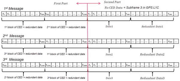
First, the message is split in two parts: the first part carries the CED as well as its redundant data, the second part (equivalent to subframe 3 of the GPS L1C message) carries additional data (refer to figure 2). The first part can carry three different messages, described as follows (considering as an example that the CED represents 600 bits):
· The first message sends the first and the second blocks of CED and redundant data. With this information, we are able to retrieve the CED with the same resilience as a Root-LDPC code of rate 1/2.
· The second message sends the third and the first blocks of CED and redundant data. With this information we are capable to retrieve the CED with the same resilience as a Root-LDPC code of rate 1/2. Moreover, if we have already received the first message, we can enhance the resilience of the data since we have data equivalent to a channel coding scheme of 1/3.
· The third message sends the second and the third blocks of CED and redundant data. With this information we are capable to retrieve the CED with the same resilience as a Root-LDPC code of rate 1/2. Moreover, if we have already received the second message, we can enhance the resilience of the data.
The former example is illustrated in figure 2.
Let’s present the rate compatible root LDPC parity check matrix for a code rate 1/3: !
=
⎝
⎜
⎜
⎛
#
%%0
0
D% P% Q%0
0
0
#
%'0
0
0
0
0
R' S' T' %E 'E EE#
DE0
0
0
0
0
0
0
0
#
DD0
0
RD SD TD %P 'P EP0
0
0
#
RP0
0
0
0
0
DQ PQ QQ#
RQ0
0 ⎠
⎟
⎟
⎞
(6)where #$,X are identity matrices , $,X are a combination of QC matrices [5] with different Hamming weights and subindexes ) and F represent the column and row position inside the matrix. It must be remarked that the 3 first columns represent the information sent in the first block fading (first part of the 1st message and second part of the 2nd message), the columns 4-6 represent the information sent in the second block fading (second part of the 1st message and first part of the 3rd message) and the columns 7-9 represent the information sent in the third block fading (first part of the 2nd message and second part of the 3rd message).
As it happened for the root codes, in order to compute the generator matrix, the submatrix corresponding to the redundant data must be full rank. Let’s re-structure the parity check matrix by inserting the systematic information in the first columns as it is illustrated in (7).
!
=
⎝
⎜
⎜
⎛
#
%% D%0
0
0
P% Q%0
0
#
%'0
R'0
0
0
0
S' T' %E#
DE0
'E EE0
0
0
0
0
#
DD RD0
0
0
0
SD TD %P0
#
RP 'P EP0
0
0
0
0
DQ#
RQ0
0
PQ QQ0
0 ⎠
⎟
⎟
⎞
=(
- .)
(7)where - represents the 3 first columns of the matrix and . represents the reminder information of the matrix (corresponding to the parity information bits).
The decoding algorithm for the rate compatible root LDPC codes follows the same methodology as the Root-codes [2], [4]. Thanks to the MDS property under the BP algorithm, once one block of information is retrieved, the BP algorithm can be used to decode the information and to retrieve the CED.
IV- RESULTS
In order to compare the performances of the error correcting solutions proposed in section III with previous works, the TTD (and thus indirectly the TTFF) and the retrieved CED Error Rate (CEDER) are evaluated in an Additive White Gaussian Noise (AWGN) propagation channel model.
Time To Data (TTD)
The following analysis considers the subsequent assumptions: · The Time of Week (TOW) is known.
· The results are expressed in terms of the TTD values.
In order to obtain the TTD values, we need to define the Probability Density Function (PDF) of the TTD. The TTD can then be obtained from the Cumulative Distribution Function (CDF) defined in (9).
@\L(^77_) = ` a\L(b)cb 7dde
9f = g
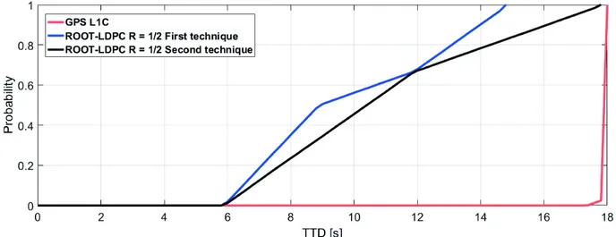
where x describes the percentage of confidence needed in order to represent the time needed by the receiver to retrieve the CED. The new advanced co-design technique schemes are compared in Figure 3 with the GPS L1C CED error correcting scheme and with the former proposed Root-LDPC code scheme of rate ½ under the AWGN channel assumption.
Simulation results show a reduction of 50 % of TTD for at least 50 % of the time under C/N0 = 45 dBHz channel
conditions compared to the current GPS L1C subframe 2 message thanks to the first advanced technique. This is mainly due to the use of an erasure decoding algorithm and to the reinforcement of the design constraints of the Root-LDPC matrix). In case of the second technique, the same performances than the former root LDPC scheme (black line) under high C/N0 channel conditions are observed, however a huge increment of the error correction capabilities can be
accomplished once three blocks of information are received.
Fig. 3. Cumulative Distribution Function under AWGN Channel with C/N0= 45 dBHz
Retrieved CED Error Probability
In order to evaluate the error correcting algorithms capabilities, the CEDER, which is equivalent to the evaluation of the probability of retrieving the CED under one specific C/N0 value, is calculated under the AWGN channel assumption.
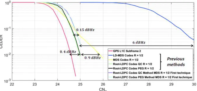
For the first method (reinforce design constraints of the root LDPC parity check matrix), we assume that the entire GPS L1C subframe 2 (600 bits of systematic information and 600 redundant bits) has been retrieved. In Figure 4 the CEDER in terms of C/N0 for the first method along with the CEDER of channel coding schemes proposed in [2] (lowest density
maximum distance separable (LD-MDS) codes, maximum distance separable (MDS) codes, root LDPC QC codes and root LDPC Progressive Edge Grown (PEG) codes) are illustrated.
Simulation results show that root LDPC codes obtain the best demodulation threshold compared with LD-MDS and MDS codes (demodulation threshold gain of 6 dBHz and 0.9 dBHz respectively for a targeted error probability of 109'). In addition, it’s important to notice that a small difference in the error correcting performance between the
Root–LDPC and the first advanced technique with the current GPS L1C message (just 0.4 dBHz and 0.55 dBHz) along with the MDS property, can provide a channel coding scheme which accomplishes a major reduction in the TTD (leading to a major reduction in the TTFF) without degrading the demodulation threshold.
Moreover, a small gap of 0.15 dBHz between the Root-LDPC codes and the codes developed for the first advanced technique can be appreciated. This small reduction of the performance stems from the increment of the parity check matrix structure requirements. However, thanks to the extra requirement along with the new erasure decoding algorithm a reduction of the TTD can be achieved.
Fig. 4. CEDER under AGWN Channel The same study is done for the second advanced technique.
· CEDER simulation results from the second technique codes of rate 1/3 after retrieving 2 blocks of data (corresponding to the curves in purple, cyan and blue) illustrate a demodulation threshold almost equal to the Root-LDPC code of rate ½ (gap of 0.15 dBHz) for a targeted error probability of 109'.
· CEDER simulation results from the second technique codes of rate 1/3 after retrieving 3 blocks of data (corresponding to the curve in yellow) illustrate a demodulation threshold gain of 1.6 dBHz and 1.2 dBHz compared to the Root-LDPC code of rate 1/2and GPS L1C for a targeted error probability of 109'.
In order to enhance the TTD reduction capability, the demodulation threshold gain (finally involving a reduction of the time to acquire the data) can be viewed as a counterpart to the decreasing of the data rate (which corresponds to the increasing of the number of redundant bits).
Fig. 5. CEDER under AWGN Channel
V- CONCLUSIONS
To sum up, two advanced techniques in the co-design of the message structure and the channel coding are proposed in order to reduce the TTFF and to enhance the demodulation performances. The first technique proposes to reinforce the
parity check matrix constraints of a root LDPC code of rate 1/2 along with the design of an erasure decoding algorithm in order to reduce the TTD. A reduction of the TTD is appreciated under good channel condition without undermining the CEDER results. The second advance technique proposes a change in the paradigm of how to co-design the message structure and the channel coding scheme thanks to a new family of codes inspired in the rate compatible root LDPC codes. Thanks to this new methodology of design, the resilience of the CED is highly enhanced compared to former schemes of co-designing (such as GPS L1C subframe 2). This is achieved thanks to the new message structure, which allows coding rates lower than 1/2 and provides higher robustness under harsh environments (low C/N0).
REFERENCES
[1] Birgit E. Schotsch, Marco Anghileri, Thomas Burger, Mahamoudou Ouedraogo, “Joint Time-to-CED Reduction and Improvement of CED Robustness in the Galileo I/NAV Message”. "Proceedings of the 30th International Technical Meeting of The Satellite Division of the Institute of Navigation (ION GNSS+ 2017), Portland, Oregon, September 2017.
[2] Lorenzo Ortega Espluga, Charly Poulliat, Marie-Laure Boucheret, Marion Aubault, Hanaa Al Bitar. Co-design of message Structure and Channel Coding Scheme to Reduce the Time to CED and to Improve the Resilience for a Galileo 2nd Generation New Signal. ION GNSS+, Miami, Florida, USA, 24/09/2018-28/09/2018,
[3] Lorenzo Ortega Espluga, Charly Poulliat, Marie-Laure Boucheret, Marion Aubault, Hanaa Al Bitar. New Solutions to Reduce the Time-To-CED and to Improve the CED Robustness of the Galileo I/NAV Message. ION POSITION LOCATION AND NAVIGATION SYMPOSIUM (PLANS 2018), Monterey, California, USA, 23/04/2018-26/04/2018
[4] J. Boutros A. Guillen i Fabregas E. Biglieri G. Zemor "Low-density parity-check codes for Nonergodic Block-Fading Channels” IEEE Trans. Inf. Theory vol. 56 no. 9 pp. 4286-4300 Sep. 2010.
[5] E. Biglieri J. Proakis S. Shamai "Fading channels: Information-theoretic and communication aspects" IEEE Trans. Inf. Theory vol. 44 pp. 2619-2692 October 1998.
[6] Y. Li and M. Salehi "Quasi-cyclic LDPC code design for block-fading channels " in Information Sciences and Systems (CISS) 2010 44th Annual Conference on pp. 1-5 Mar 2010.
[7] A. G. D. Uchoa C. Healy R. C. de Lamare and R. D. Souza "Design of LDPC Codes Based on Progressive Edge Growth Techniques for Block Fading Channels "IEEE COMMUNICATIONS LETTERS VOL. 15 NO. 11 pp. 1221-1223 Nov. 2011
[8] Y. Fang Y. L. Guan G. Bi L. Wang F. C.M. Lau "Rate-compatible root-protograph LDPC codes for quasi-static fading relay channels" IEEE Trans. Veh. Technol vol. 65 no. 4 pp. 2741-2747 Apr. 2016.