To link to this article:
DOI : 10.1016/j.wear.2016.11.007
URL :
http://dx.doi.org/10.1016/j.wear.2016.11.007
This is an author-deposited version published in:
http://oatao.univ-toulouse.fr/
Eprints ID:
19713
To cite this version:
Delebarre, Corentin and Wagner, Vincent and Paris, Jean-Yves and
Dessein, Gilles and Denape, Jean and Gurt-Santanach, Julien Tribological
characterization of a labyrinth-abradable interaction in a turbo engine
application. (2017) Wear, vol. 370-371. pp. 29-38. ISSN 0043-1648
O
pen
A
rchive
T
oulouse
A
rchive
O
uverte (
OATAO
)
OATAO is an open access repository that collects the work of Toulouse researchers and
makes it freely available over the web where possible.
Any correspondence concerning this service should be sent to the repository
administrator:
[email protected]
Tribological characterization of a labyrinth-abradable interaction in a
turbo engine application
C. Delebarre
a,n, V. Wagner
a, J.Y. Paris
a, G. Dessein
a, J. Denape
a, J. Gurt-Santanach
b aLaboratoire Génie de Production, INP-ENIT, Université de Toulouse, Tarbes, FrancebSAFRAN HELICOPTER ENGINES, Avenue Joseph Szydlowski, 64510 Bordes, France
Keywords: Labyrinth seal Thermal spray coatings High speed interaction Tribological circuit Wear dynamics Interaction life cycle
a b s t r a c t
To enhance the efficiency of a turbo engine, one solution is reducing the clearance between the rotary parts in the secondary air system. This clearance reduction causes direct interactions in the secondary air system of a turbo engine when a rotary seal, called a labyrinth seal, rubs against the turbo engine casing as a result of successive starts and stops, thermal expansions and vibrations. To protect sealing systems from severe damage, abradable coatings are used on the inner periphery of the casing. The purpose of the present paper is to study the labyrinth-abradable interaction during high speed contacts through a detailed tribological characterization. The labyrinth-abradable interaction experiments were conducted on a dedicated test rig that was able to reproduce representative turbo engine operating conditions. A complete tribological analysis based on a third body approach and on accommodation flows was in-vestigated using high speed imaging of the interaction. A schematic description of the interaction, with the addition of images extracted from recorded videos, is proposed to define two types of third body formation and their evolution during labyrinth-abradable interactions. Finally, the labyrinth-abradable interaction life cycle was used as a basis to discuss the coating subject to a labyrinth tip speed increase.
1. Introduction
Minimizing the interfering leakage between the rotating as-sembly and stationary parts of a turbo engine is crucial for im-proving the efficiency of engine modules ([1]). Secondary turbo engine air sealing systems are composed of a particular type of rotary seal called the labyrinth seal. The control of pressure dif-ferences and levels of cooling between the engine modules is provided by the clearance control between the rotating labyrinth teeth and surrounding casing. The rotary seals are primarily composed of several teeth, which are integral parts of the motor shaft. This constraint requires the turbo engine designers to de-posit a sacrificial abradable coating on the casing that is specially designed to protect the integrity of the seal components ([2,3]). One of the most important properties of this coating is to ac-commodate incursions of the labyrinth teeth that might occur during turbo engine operation ([4]). Indeed, a turbo engine is subjected to successive start and stop cycles, thermal expansions, vibrations, and mechanical loading creating undesirable rotor-stator displacements leading to labyrinth seal interactions ([5,6]). The coating abradability and the turbo engine operating
environment imposes requirements in coating design that are the result of a compromise among various coating properties ([7]). Knowledge and control of the wear behaviour of abradable coat-ings are required to maintain an optimum seal for the proper functioning of engines ([8]).
Research on the labyrinth seal behaviour has mainly focused on sealing performance. Many numerical studies aimed to char-acterize the sealing performance according to various tooth parameters ([9]), seal geometry ([10]), rate of leakage caused by the rub-groove left by the teeth on the coating ([11–13]) and so on. Very few studies have attempted to reproduce the labyrinth-abradable interaction using a dedicated test rig to study the be-haviour of the coatings. A first full-scale facility, based on a grinding machine, has been developed by Dowson et al. ([14,15]) to study the behaviour of several abradable coatings (silicone rubber, tetrafluoroethylene (TFE), aluminium silicon-polyester, nickel graphite). The authors established an abradability condition based the ratio between the rub-groove penetration depth in the coating and the wear of the labyrinth seal to discuss their beha-viour. Visual descriptions of the rub-grooves left by the labyrinth seal on the coating are used to describe the quality of the rub-groove (edges and sides), presence of cracking caused by thermal effects and increase in the coating hardness. Later, Whalen et al. ([16]) summarized all of the studies on the development of poly-mer coatings for centrifugal compressors and developed new
n
Corresponding author.
labyrinth seal design geometries, such as labyrinth seals that in-corporate teeth on the stator. In addition, the companies Sulzer Innotec and Sulzer Metco worked closely to develop coatings that were specially adapted for labyrinth-abradable applications ([17]). More recently, Delebarre et al. ([18]) developed a new high speed test rig based on a milling machine that was dedicated to stimu-lating interactions between labyrinth seals and abradable coatings under similar turbo engine operating conditions. A contact as-sessment under different turbo engine operating conditions has been carried out between an Al-Si 6% coating and a nickel alloy (Alloy718) labyrinth seal.
In a more precise understanding of the wear mechanisms in-volved, Delebarre et al. ([19]) studied interactions as a function of the incursion depth parameter to obtain a first chronological contact evolution under severe operating tribological conditions. Using a suitable instrument, macrographic and micrographic rub-groove observations are used to describe the wear process using a preliminary third body approach. Two different varieties of parti-cle production have been identified providing two different types of third body and two different material flows. Finally, the authors demonstrated that the evolution of the third body and its life cycle during contact have a major impact on the final rub-groove mor-phology. This approach is reflected in several studies concerning interactions encountered between compressor blade casings in the primary turbo engine air system ([20,21]). The mechanisms of incursion accommodation were investigated using dynamic data and a post mortem analysis of the rubbed coating and wear debris. The authors proposed a schematic description of the accom-modation mechanisms ([21]).
The present paper proposes a complete tribological analysis of the labyrinth-abradable interaction based on the description of the contact life cycle interaction. The test rig presented in previous papers ([18,19]), is used to simulate in-service interactions with respect to the full scale, integrating dedicated high speed imaging of the interaction. Our efforts are focused on conducting a tribo-logical analysis of a specific interaction condition (“the severe wear condition” ([19])) between an Al-Si 6% coating and a stainless steel labyrinth seal. This experiment is representative of the most substantiated contact condition that occurs in turbo engine life in terms of the materials used, relative rotor/stator speeds (labyrinth tip speed of17 m s· −1) and kinematic interactions of the labyrinth
seal (incursion speedVinc=9.41 m·s−1). The high speed imaging of
this specific condition and results of a previous study ([19]) are used to define an accurate interaction life cycle based on a third
body approach and on the definition of a tribological circuit. The labyrinth-abradable interaction life cycle will be used as a basis to discuss the behaviour of a coating subjected to a labyrinth tip speed increase to reach a conclusion regarding the coating behaviour.
2. Labyrinth-abradable interaction 2.1. Test rig
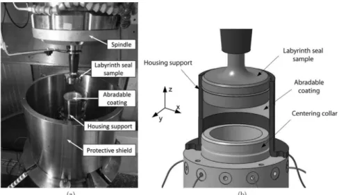
To simulate the interaction dynamics between labyrinth seals and abradable coatings, a dedicated test rig, discussed in detail in previous papers ([18,19]), was used in this study. The test rig configuration remains unchanged and allows the test rig to re-produce labyrinth seal interactions under operating conditions similar to those of a turbo engine. As shown in Fig. 1a, a 5-axis milling machine from Mikron and a special device fitted on the machine tool table are used to reproduce the working in-service kinematics of the labyrinth seal. A labyrinth seal sample, re-presentative of an actual motorshaft section part, shrinks on the HSK-50 tool holder instead of the cutting tool. A simplified geo-metry was chosen for the labyrinth seal sample using a single tooth configuration with respect to full-scale turbo engine com-ponents. The labyrinth tip speed Vtis generated by spinning the
labyrinth seal sample through a magnetic bearings spindle ([22]). A tube sample, representative of a turbo engine housing, is coated in the inner periphery with an abradable material. Once the la-byrinth seal sample is precisely positioned inside the housing support (Fig. 1b), the CNC capabilities of the 5-axis milling ma-chine (machining program executed by the CNC) are used to make labyrinth-abradable contacts under realistic and controlled oper-ating conditions. The contact is generated by a translation of the housing support and is defined by an incursion speed Vincand a
penetration depth Dpin the coating, generating a particular
in-teraction area that is induced by the radial incursion of a circular tooth (with a trapezoidal section) in a tube.
The first investigations of the labyrinth-abradable interactions were achieved using the in-situ instrumentation that was specially developed on the test rig ([18,19]). The labyrinth seal tooth tip penetration depth Dpin the coating and the interaction time t are
estimated through a contact tracking sensor (voltage circuit gen-erated by the opening and closing of the circuit between the la-byrinth seal tooth and coating). A continuous acquisition of this
Fig. 1. (a) Overview of the dedicated test rig that was specially developed to simulate labyrinth-abradable interactions; (b) closer view of the labyrinth seal sample precisely positioned inside the housing support.
sensor, at a sampling frequency of 15 kHz, also allows us to observe the effects of the labyrinth seal tooth tip geometrical defects during contact (rotor unbalance). Moreover, a built-in dynam-ometer has been developed to estimate the interaction contact forces. The control current signals of the magnetic bearings spin-dle are post-processed to estimate the normal fn, the tangential ft
and the axial fzcomponents of the interaction forces (Fig. 2). The
details of the special instrumentation were discussed and de-scribed in a previous study ([18]). However, these in-situ mea-surements are not sufficient and have to be complemented by the contribution of the high speed imaging of the interaction.
2.2. High speed imaging test rig configuration
A high-speed camera (PHOTRON Fastcam SA1, objective (X100)) with a capture capacity of 5000 frames s·−1was set up to investigate the dynamics of the wear mechanisms and labyrinth seal tooth motion during the interaction (Fig. 3a). However, be-cause of the contact confinement, significant modifications were made to the test rig configuration, especially on the housing support design, to observe the complete interaction. The use of a half section of the housing support was selected to obtain a con-tact that had an open geometry, offering the possibility of partially observing the labyrinth-abradable interaction (Fig. 3b).
The observation area is focused on the Al-Si 6% coating section, which had previously been precisely cut at the maximum tooth penetration depth Dp(Fig. 4). The labyrinth seal rotational
direc-tion is set to guide the particles ejected from the contact to the high speed camera lens. Although the contact confinement and its influence are not representative of real interactions, the rotational direction and contact configuration allow the observation of the wear mechanisms from the labyrinth tooth entry during contact to the maximum penetration depth Dp.
2.3. Operating conditions
2.3.1. General in-service interaction conditions
To study the tribological behaviour of the Al-Si 6% abradable coating, conventional parameters, such as the labyrinth tip speed Vt, the incursion speed Vinc and the penetration depth Dp
(pre-viously defined in papers) were used to simulate in-service la-byrinth-abradable interactions ([18]). The penetration depth Dpof
the labyrinth tooth in the coating is kept constant, defining an imposed wear interaction, which is an important contact feature. The coupling of control parameters (Vt, Vincand Dp) and the
var-ious tested values (listed inTable 1) cover a range of various in-teraction conditions that are encountered during the functioning of the turbo engine. Among these conditions, a specific condition, identified as the most substantiated contact condition for the la-byrinth-abradable system, was chosen for detailed analysis. The coupling of a high incursion speed (Vinc=9.41 mm s· −)
1
and a low labyrinth tip speed (Vt=17 m s· −)
1
defines this specific condition and is the result of a transient dynamic of the turbo engine mo-torshaft (during the start-up and shutdown phases), which is caused by the resonance frequency of a vibration mode. Based on the results of this specific condition, an increase of the labyrinth tip speed Vtwas investigated to cover the range of service
in-teraction conditions. In this way, the test matrix was conditioned by a single incursion speed Vinc, generating a specific interaction
kinematic that required precise characterization (cfSection 2.3.2). 2.3.2. Interaction kinematics of the specific condition
Despite the precise machining of the labyrinth seal specimen, the kinematics of the labyrinth seal tooth tip (main contact surface with the coating) are disturbed by the geometric defects of the rotating labyrinth seal specimen. The high speed imaging of the
5 10 15 20 25 30 35 40 45 50 0 10 20 30 5 10 15 20 25 30 35 40 45 50 0 10 20 30 Interaction forces (N) 5 10 15 20 25 30 35 40 45 50 0 10 20 30 Time (s)
f
nf
tf
zFig. 2. Typical signals of the interaction force components ( fn,ftandfz).
Fig. 3. (a) Test rig configuration enabling the high speed imaging of the interaction; (b) schematic description of the interaction area observed. Fig. 4. Example of the camera field of view.
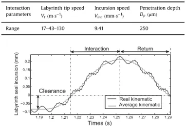
labyrinth seal in rotation highlighted an axial and radial runout (respectively 20 m andμ 36 m) of the tooth tip, which has sig-μ nificant importance for the contact kinematics.Fig. 5presents the real interaction kinematic (of the labyrinth seal tooth tip) super-imposed on the average kinematic (translation of the labyrinth seal specimen) for the specific condition. The real kinematic is affected by a sine wave with a period of one labyrinth seal rotation and an amplitude equal to the value of the radial runout. The re-sulting sinusoidal profile (function of the labyrinth tip speed Vt
value) added to a translation displacement at a high incursion speed (Vinc=9.41 mm s·−)
1
generates a specific set of contact con-ditions that are marked by tooth returns in the direction opposite to the incursion. The contact condition is described as permanent for the specific condition (Vinc=9.41 mm s·−1, Vt=17 m s· −1 and
= μ
Dp 250 m) because the effect of the radial runout is compen-sated by a high incursion speed, Vinc. Moreover, the axial runout
generates a slide turning of the abradable coating during the in-cursion, which is considered for the result of the study. A tribo-logical study considering these observations is described in the following section.
3. Tribological analysis of the labyrinth-abradable dynamics A tribological approach based on the concepts of the third body ([23]), tribological triplet ([24,25]) and tribological circuit ([26]) is used to study the specific interaction to precisely define the life of the contact. The concept of the third body, considering an inter-mediate element between two materials in contact, was in-troduced in ([23]) and adds an important parameter to the study of friction and wear mechanisms ([27]). A tribological system is then composed of a three-level subsystem: the tribological triplet. 3.1. Tribological triplet
The tribological triplet applied to the labyrinth-abradable in-teraction is defined in this study by a test device (the test rig) consisting of the milling machine and, more particularly, of the magnetic bearings spindle and machine tool table (Fig. 6). The test device requires knowledge of the operating conditions (interaction kinematic, incursion speed Vinc, penetration depth Dp, runout etc.)
and transmits the load and type of stress. The first bodies (contact elements) are defined as the labyrinth seal tooth and abradable coating, Al-Si 6%. These two bodies undergo the device conditions
that are generated by responding to volumetric or superficial transformations. Finally, a third body is defined as a dynamic element located at the interface between the two first bodies. The third body transmits the load from one solid to another and be-tween contact elements and flows that accommodate most of the speed difference between the two solids.
According to the post mortem observations of the rubbed coating and analysis of the interaction signals, performed in a previous study ([19]), two types of third body were identified:
!
The first type of third body represents the pulverulent fine powder particles ejected from the contact by the majority abrasion mechanism of Al-Si-6% ([19]).!
The second type of third body consists of an adhering layer at the interface between the tooth and coating in the smooth and cohesive rub-groove bottom, which is formed by abrasion par-ticles of Al-Si 6% trapped (confinement) in contact ([19]). A schematic description of the interactions, along with some images extracted from the recorded videos, is proposed in the following section to define the formation of the two types of third body and their evolution during the interaction.3.2. High speed imaging under specific conditions
This section presents the results of high speed imaging under the specific conditions ( Vinc=9.41 mm s·−
1
, Vt=17 m s· −
1
and = μ
Dp 250 m) that were used to focus on the Al-Si 6% wear me-chanism dynamics. An extracted image from the video is pre-sented inFig. 7a and shows the side view of the contact between the labyrinth seal and coating. The analysis of the resulting video allowed the precise identification of:
!
the actual incursion depth Dpof the labyrinth seal tooth into thecoating during the interaction by measuring the position of the tooth tip surface compared to the abradable coating surface (Fig. 7a),
!
the continuous ejection of a large amount of fine particles (≃10 m) in the form of a small amount of cohesive powder thatμ was mainly formed by an abrasion mechanism of Al-Si 6% in the direction of the labyrinth seal rotation (Fig. 7b),!
the initial Al-Si 6% deformation mechanism around the tooth atTable 1
Test parameters defining the test matrix.
Interaction Labyrinth tip speed Incursion speed Penetration depth parameters Vt(m s·−1) V
inc(mm s·−1) Dp(μm)
Range 17–43–130 9.41 250
Fig. 5. Interaction kinematic of the specific condition ( Vinc=9.41 mm s·−1, = ·−
Vt 17 m s1andDp=250 mμ ).
Fig. 6. Schematic description of the tribological triplet applied to the labyrinth-abradable interaction.
the beginning of the interaction, creating a material accumula-tion on either side of the rub-groove (Fig. 8). This initial deformation illustrates the high Al-Si 6% ductility, which is enhanced by the pressure from the labyrinth seal tooth on the coating,
!
the formation and evolution of the adhering layer at the inter-face between the tooth and Al-Si 6% coating. This layer is in-itially formed by a mechanism showing a high level of con-finement of abrasion particles induced by the labyrinth seal tooth tip surface (Fig. 8),!
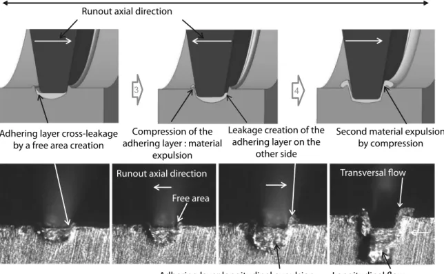
different material flows of the adhering layer in two directions during the labyrinth seal tooth incursion (Fig. 9): a longitudinal flow characterized by a material ejection in the direction of the labyrinth seal rotation (toward the lens of the camera) and a transverse flow along the inclined flange of the tooth. The transverse flow is generated by the expulsion of the adhering layer using a free space generated by the axial runout of the labyrinth seal tooth.!
the influence of axial runout compressing the adhering layer and creating a material expulsion (Fig. 9).Fig. 8describes the three main steps of adhering layer formation at the interface between the labyrinth seal tooth and Al-Si 6% coating occurring at the beginning of the interaction. These steps are illustrated using images from recorded videos during the specific test condition.
Once the adhering layer was created under the tooth, according to the combined action of the abrasive particles trapped by the tooth and the high pressure (confinement) exerted by the high incursion speed Vincin the coating, major changes of the adhering
layer were observed during a full rotation of the tooth and are illustrated inFig. 9. Moreover, a recycling phenomenon of abrasion particles was identified by performing an additional test that has the particularity of reversing the direction of rotation of the la-byrinth seal. This test configuration allowed us to study either the output or contact entry of the interaction and to observe Al-Si 6% adhesive transfer on the labyrinth seal tooth.Fig. 10 shows the ejection of Al-Si 6% fragments (in the direction of the lens) that were initially transferred to the tooth and stopped by the sharp edge offered by the coating section. These fragments demonstrate the adhesive behaviour of Al-Si-6% during the interaction, leading to a recycling phenomenon during contact.
3.3. Tribological circuit
The presence of a third body in the contact caused by the es-tablishment of a velocity gradient produced an accommodation phenomenon between the two first bodies. Berthier et al. ([26]) modelled the life of debris in the contact using a tribological system combining different material flows that were associated with third body circulation. Previous observations allowed the labyrinth-abradable tribological circuit to be defined according to
Fig. 7. High speed imaging under a specific test condition (Vinc=9.41 mm s·−1,Vt=17 m s·−1andDp=250 mμ ): a) identification of the actual penetration depth Dp and b)
ejection of pulverulent particles by abrasion phenomenon.
two different contact perspectives. A cross sectional view of the interaction (Fig. 11a) and a longitudinal section (Fig. 11b) are used to fully describe the third body circulation. The three main ma-terial flows that regulate the interaction are illustrated in detailed diagrams.
!
Source flows (Qs) are defined as particles that are generated from Al-Si 6% wear (Qscoat) and/or from the tooth (Qstooth) andquantify the material input contribution toward the creation of the third body. In the case of the specific conditions studied here, the tooth wear Qstoothis insignificant. Therefore, the source
flow Qs is equal to Qscoat. The source flow Qscoat supplies the
contact by particles from the abrasion mechanism of the Al-Si 6% coating.
!
An internal flow Qiquantifies the third body circulation. At theinterface between the labyrinth seal and tooth, the third body circulation is primarily composed of Al-Si 6% particles (adhering layer). Two different types of internal flow are highlighted using
Fig. 9. Evolution of the adhering layer on the rub-groove bottom during a full labyrinth seal tooth rotation. (The thickness of the coatings shown in the images is 1 mm).
Fig. 10. Al-Si 6% adhesive transfer on the labyrinth seal tooth, demonstrating a recycling phenomenon during the interaction (The width of the tip incursion marks in Fig. 9 and 10 is 350 mm).
high speed imaging of the interaction: a longitudinal flow Qi1
characterizing the adhering layer ejection in the direction of rotation of the tooth and a transverse flow Qi2illustrating the
expulsion of the adhering layer along the inclined edges of the tooth.
!
An external flow Qeis representative of the debris ejection ofAl-Si 6% powder, largely stemming from the third body abrasion mechanism caused by tooth rotation. A portion of the particles from the external flow Qe feeds into recycling flow Qr,
char-acterized by a third body transfer of the tooth (Al-Si 6% transfer) and by powdered particles that are trapped due to a high con-finement. Finally, the wear flow Quincludes all of the Al-Si 6%
particles from the external flow Qeto be ejected from the
con-tact.
The identification of these different flows, which are in agreement with the tribological circuit, enables us to establish a mass balance of the specific interaction (Eq.(1)). As described above, each type of flow could be divided into two components (Eqs.(2),(3)and(4)):
( ) = ( ) + ( ) ( ) Q ts Q ti Q te 1 = + ( ) Qs Qscoat Qstooth 2 = ( ) + ( ) ( ) Qi Qi1longitudinal Qi2transversal 3 = + ( ) Qe Qr Qu 4
Knowing the interaction time t, a quantitative estimation of the different flows (m s3· −1) could be proposed by calculating the
material volumes associated with the various defined flows. In spite of difficulties and the feasibility of quantifying certain material volumes during the interaction, only a flow proportion estimate (%) is possible using images from high speed imaging, from a sectional view, of the rub-groove at the end of the interaction (Fig. 9). In this way, a first estimate of different flow proportions is proposed, particularly between the internal flow Qi (volume of material
flowing, Eq. (6)) and the external flow Qe (removed material
volume, Eq. (7)), defining the source flow Qs(Eq. (5)). Only the
estimate of the recycling flow proportions is arbitrarily fixed (not visible on images) to integrate its influence into the equation (Eq.
(7)). A first estimation of the mass balance of the specific condition is proposed with an accuracy of 710 (Eq.(8)).
( ) = = ( ) + ( ) ( ) Q ts Qscoat 0.3Q ti 0.7Q te 5 = + ( ) Qi 0.5Qi1 0.5Qi2 6 = + ( ) Qe 0.9Qu 0.1Qr 7 = = + + + ( ) Qs Qs 0.15Q 0.15Q 0.63Q 0.07Q 8 rev i1 i2 u r
3.4. Contact life cycle
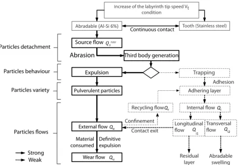
The tribological approach of the labyrinth-abradable interac-tion is used to methodically describe the wear mechanism dy-namics that are involved in the contact and the corresponding tribological circuit. The diagram shown inFig. 12summarizes the labyrinth-abradable life cycle applied to a specific test condition. This organizational chart integrates a quantitative estimate of the strong (solid arrows) or low (dashed arrows) presence of the highlighted phenomena.
According to our results, a gradual increase in the labyrinth tip speed Vt is investigated in the following section to study its
in-fluence on the contact life cycle.
4. Additional tests at a higher labyrinth tip speed
This section primarily concerns the influence of the labyrinth seal tip speed Vton the Al-Si 6% coating behaviour in terms of the
interaction of forces that are generated by contact and of contact life cycle evolution using high speed imaging of the interaction. Two additional tests have been performed with two faster labyr-inth tip speeds Vt(Vt=43, 130 m s· −)
1(cf.Section 2.3.1), and with an
identical incursion depth Dp=250 mμ and incursion speed = · −
Vinc 9.41 mm s 1. The results of the interaction are compared to the specific test condition previously studied (Vinc=9.41 mm s·−1,
= ·−
Vt 17 m s 1andDp=250 mμ ).Fig. 13shows the interaction force
profiles (normal fn, tangential ftand axial fzcomponents) aand the
labyrinth seal tooth incursion depth Dprecorded during the
in-teraction. The force signal profiles are similar, leading to a com-parison of the maximum interaction forces that are reached for each component during the interaction. An increase in the labyr-inth tip speed leads to a significant reduction of forces generated during the interaction, inducing changes in the Al-Si 6% behaviour, which may be produced by the decrease in the adhesive behaviour of Al-Si 6% (the smaller adhering layer proportion) or the increase of the abrasion wear mechanism (higher particle ejection).
Observations from the high speed imaging of the overall in-teractions were correlated with the interaction forces to identify the phenomenon that caused the decrease in contact forces. Images from the recorded videos confirmed that the ejection of Al-Si 6% pulverulent particles from the contact is more important at a maximum speed ofVt=130 m s· −1(Fig. 14a and b). The brightness and contrast of the images are deliberately increased to fully dis-cern the ejection of particle. Post mortem images (Fig. 15) from the recorded videos of the three test conditions that simulated a la-byrinth tip speed test increase from Vt=17 m s·−
1 (Fig. 15a), = ·− Vt 43 m s 1(Fig. 15b) to = · − Vt 130 m s
1(Fig. 15c) show the
evo-lution of different material flows and their associated proportions. The abradable adhering layer thickness at the interface between the tooth and abradable coating decreases when the labyrinth tip speed Vtincreases. AtVt=43 m s· −1, the amount of material ejected
toward the lens of the camera reveals a decrease in the proportion of longitudinal flow compared to Vt=17 m s· −
1
(Fig. 15b). This observation is identical to that of the transverse flow generated by the expulsion of the adhering layer on both sides of the
rub-Fig. 12. Organizational chart of the labyrinth-abradable interaction life cycle ap-plied to a specific test condition ( Vinc=9.41 mm s·−1, Vt=17 m s·−1 and
= μ
Fig. 13. Components of the interaction forces (fn normal, fttangential, fzaxial) and associated penetration depth Dp profiles: a) Vt=17 m s·−1, b) Vt=43 m s·−1, c)
= ·−
Vt 130 m s 1.
Fig. 14. Images of the influence of the labyrinth tip speed Vton the ejection of pulverulent particles of Al-Si-6%: a)Vt=17 m s·−1, b)Vt=130 m s·−1. (The thickness of the
coatings shown in the images is 1 mm).
Fig. 15. Images of the influence of the labyrinth tip speed Vton the material flows: a)Vt=17 m s·−1, b)Vt=43 m s·−1, c)Vt=130 m s·−1. (The thickness of the coatings shown in
groove. In the case of the test performed at Vt=130 m s· −
1, the
proportions of internal flow are significantly reduced and the rub-groove morphology is more “clear cut” (Fig. 15c). The increase of the abrasion performance of the labyrinth seal tooth (by increasing the labyrinth tip speed Vt) allows the generation of a large amount
of ejected particles from the contact (pulverulent particles) and thereby reduces the formation of the adhering layer. The long-itudinal and transverse flows are substantially reduced.
The organizational chart shown inFig. 16summarizes the im-pact of the labyrinth tip speed Vt increase on the
labyrinth-abradable contact life cycle. An increase of the tooth speed high-lights the preponderance of the third body expulsion circuit compared to the formation of an adhering layer at the tooth/ coating interface. This chart may also be illustrated by the mass balance (Eq.(9)), expressed by variations of different flow pro-portions that compose the overall mass balance of the specific condition.
= = ↘ + ↘ + ↗ + ↘ ( )
Qs Qsrev Qi1 Qi2 Qu Qr 9
These results suggest that for a labyrinth tip speed ≥ ·−
Vt 130 m s1, the adhering layer formation circuit becomes in-significant compared to particle expulsion outside the contact. Thus, this result would lead to a simplified mass balance (Eq.(10)).
= = ( )
Qs Qsrev Qu 10
5. Conclusions
To enhance turbo-engine efficiency by reducing the mechanical clearance between rotary parts, a precise understanding of the dynamics of the wear mechanisms, encountered during labyrinth seals and abradable coatings interactions, are necessary. This re-quirement was studied by simulating an interaction between a labyrinth seal and an abradable coating in turbo-engine with re-spect to full scale components and using representative in-service test conditions. A specific test condition was analysed in detail to identify the dynamics of the wear mechanisms using high speed imaging of the interaction. The dynamics of the wear mechanisms of the abradable Al-Si 6% coating were investigated by means of a tribological analysis based on a third body approach and on the
accommodation flows. A schematic description of the interaction in addition to images extracted from recorded videos are proposed describing the most important new findings of this work:
!
two types of third body formation and their evolution during the interaction have been highlighted,!
six different material flows (two source flows associated witheach contacting material; two internal flows divided into longitudinal and transversal flows; and two external flows (corresponding to minor recycling flows and a major wear flow)) have been identified,
!
a general tribological circuit and the contact life cycle of the specific interaction have been proposed to generate a first as-sessment of the mass balance of the interaction based on a flow proportion estimate.According to our results, the labyrinth-abradable interaction life cycle has been used as a basis to discuss the behaviour of a coating subjected to a labyrinth tip speed increase:
!
the increase of the labyrinth tip speed Vtamplified the abrasivemechanism of Al-Si 6%, leading to a large amount of fine par-ticles of Al-Si 6% being ejected from the contact,
!
internal flows were significantly reduced meaning that the la-byrinth tip speed has a significant influence on the rub-groove morphology,!
the higher the labyrinth tip speed, the more the behaviour ofthe Al-Si 6% coating is improved (preponderance of the third body expulsion circuit compared to the formation of an adher-ing layer at the tooth/coatadher-ing interface).
Acknowledgements
These investigations were supported by the European Com-mission through the FP7 E-BREAK project under grant agreement no. 314366 and by SAFRAN HELICOPTER ENGINES. The study also received financial support of the Agence Nationale de la Recherche et de la Technologie (ANRT). The support of these organisation is gratefully acknowledged.
References
[1]M. Dorfman, U. Erning, J. Mallon, Gas turbines use abradable coatings for clearance-control seals, Seal. Technol. 97 (1) (2002) 7–8.
[2] W. Dalzell, S. Sanders, G. Crawford, F. Walden, W. Woodard, Abradable seal having improved properties,uS Patent 6, 352, 264, 2002.
[3]R. Rajendran, Gas turbine coatings: an overview, Eng. Fail. Anal. 26 (0) (2012) 355–369.
[4] R. Schmid, F. Ghasripoor, M. Dorfman, X. Wie, An overview of compressor abradable thermal sprays, in: Surface Engineering International Thermal Spray Conference ITSC, 2000, pp. 406–412.
[5]G. Jacquet-Richardet, M. Torkhani, P. Cartraud, F. Thouverez, T.N. Baranger, M. Herran, C. Gibert, S. Baguet, P. Almeida, L. Peletan, Rotor to stator contacts in turbomachines. review and application, Mech. Syst. Signal Process. 40 (2) (2013) 401–420.
[6]V. Nezym, A statistical model for the effect of casing treatment recesses on compressor rotor performance, Exp. Therm. Fluid Sci. 31 (8) (2007) 1165–1176. [7] E. Lugscheider, J. Zwick, M. Hertter, D. Sporer, Control of Coating Properties of
Abradable Seals by On-line Process Diagnostics.
[8] R. Chupp, Y. Lau, F. Ghasripoor, D. Baldwin, C. Ng, T. McGovern, D. Berkeley, Development of higher temperature abradable seals for gas turbine applica-tions, ASME Turbo Expo 2004: Power for Land, Sea, and Air 4, 2004, pp. 221– 229.
[9]A. Gamal, J. Vance, Labyrinth seal leakage test: tooth profile, tooth thickness, and eccentricity effects, ASME J. Eng. Gas Turbines Power 130 (2008) 11 (pages).
[10]J. Xu, M. Ambrosia, D. Rhode, Effect of rub-groove wall angle on the leakage of abradable stepped labyrinth seals, Tribology Trans. 48 (4) (2005) 443–449. [11] D. Collins, The effects of wear on abradable honeycomb labyrinth seal, (Ph.D.
thesis), Cranfiel University, 2006.
[12]X. Jinxiang, D. Rhode, Rotordynamics of impeller eye seals with wear-damaged teeth in centrifugal compressors, Tribol. Trans. 49 (3) (2006) 328–337. [13]D. Collins, J. Teixeira, P. Crudgington, The degradation of abradable honeycomb
labyrinth seal performance due to wear, Seal. Technol. (2008) 7–10. [14] P. Dowson, M. Walker, A. Watson, Developpement of abradable and rub
tol-erant seal materials for application in centrifugal compressors and steam
turbines, in: Proceeding of the Thirty Third Turbomachinery Synopsium, 1991. [15] P. Dowson, S. Ross, C. Schuster, The investigation of suitability of abradable
seal materials for application in centrifugal compressors and steam turbines, in: Proceedings of the Twentieth Turbomachinery Symposium, 1991. [16] J. Whalen, E. Alvarez, L. Palliser, Thermoplastic labyrinth seals for centrifugal
compressors, in: Proceeding Proceedings of the Thirty Third Turbo Sympo-sium, 2004.
[17] S. Wilson, Ensuring tight seals, Tech. rep., Sulzer Technical Review 2, 2007. [18]C. Delebarre, V. Wagner, J. Paris, G. Dessein, J. Denape, J. Gurt-Santanach, An
experimental study of the high speed interaction between a labyrinth seal and an abradable coating in a turbo-engine application, Wear 316 (2014) 109–118. [19]C. Delebarre, V. Wagner, J. Paris, G. Dessein, J. Denape, J. Gurt-Santanach, The wear mechanisms occurring in a labyrinth seal/abradable contact depending on the incursion depth parameter, Mech. Ind. 17 (6) (2016) 601.
[20] J. Vincent, Experimental study of the high speed blade-abradable interactions: influence of the material and of the microstructure, (Ph.D. thesis), Uni-versitéde Lorraine, 2015.
[21] R. Mandard, Y. Desplanques, G. Hauss, J. Fabis, J. Witz, J. Meriaux, Mechanisms of incursion accommodation during interaction between a vibrating blade and an abradable coating, Wear 330 à 331, 2015, pp. 406–418.
[22] J. Gurt-Santanach, F. Crabos, S. Vaillant, P.E. Jactat, G. Dessein, Test bench and test method for a dynamic sealing system, wO Patent App. PCT/FR2013/ 052,204 (apr 10 2014).
[23] M. Godet, The third body approach: mechanical view of wear, Wear 100 (1984) 43–452.
[24] Y. Berthier, L. Vincent, M. Godet, Velocity accommodation sites and modes in tribology, Eur. J. Mech. A Solids 11 (1992) 35–47.
[25] J. Denape, Y. Berthier, L. Vincent, Wear particle life in a sliding contact under dry conditions: third body approach, in: Fundamentals of Tribology and Bridging the Gap Between the Macro-and Micro/Nanoscales, Springer, 2001, pp. 393–411.
[26] Y. Berthier, Maurice godet’s third body, in: The Third Body Concept Inter-pretation of Tribological Phenomena, Vol. 31 of Tribology Series, Elsevier, 1996, pp. 21–30.