HAL Id: tel-01139357
https://pastel.archives-ouvertes.fr/tel-01139357
Submitted on 4 Apr 2015HAL is a multi-disciplinary open access archive for the deposit and dissemination of sci-entific research documents, whether they are pub-lished or not. The documents may come from teaching and research institutions in France or abroad, or from public or private research centers.
L’archive ouverte pluridisciplinaire HAL, est destinée au dépôt et à la diffusion de documents scientifiques de niveau recherche, publiés ou non, émanant des établissements d’enseignement et de recherche français ou étrangers, des laboratoires publics ou privés.
irradiation damage
Aurélien Villani
To cite this version:
Aurélien Villani. A physics modelling framework to describe the behaviour of nano-scale multi-layer systems undergoing irradiation damage. Materials and structures in mechanics [physics.class-ph]. Ecole Nationale Supérieure des Mines de Paris, 2015. English. �NNT : 2015ENMP0002�. �tel-01139357�
T
H
È
S
E
INSTITUT DES SCIENCES ET TECHNOLOGIES
´
Ecole doctorale 432: Sciences des m´etiers de l’ing´enieur
TH`
ESE
pour obtenir le grade de docteur d´elivr´e par
L’´
Ecole Nationale Sup´
erieure des Mines de Paris
Sp´ecialit´e: “Sciences et G´enie des mat´eriaux”Pr´esent´ee et soutenue publiquement par:
VILLANI Aur´elien
le 12 f´evrier 2015
A Multi-Physics Modelling Framework to
Describe the Behaviour of Nano-Scale
Multilayer Systems Undergoing Irradiation
Damage
Mod´
elisation Multiphysique de
l’Endommagement par Irradiation de
Lamin´
es Nanocristallins
Directeurs de th`ese: Esteban P. BUSSO Samuel FOREST Jury:
Pr. Fionn Dunne, Imperial College London Rapporteur
Pr. Marc G.D. Geers, Technische Universiteit Eindhoven Rapporteur
Dr. Laurent Capolungo, Georgia Tech Lorraine Examinateur
Pr. Mohammed Cherkaoui, Georgia Tech Lorraine Pr´esident
Dr. Lionel G´el´ebart, CEA Examinateur
Pr. Esteban P. Busso, ONERA Directeur de th`ese
Pr. Samuel Forest, Ecole des Mines de Paris Directeur de th`ese
Mines ParisTech Centre des Mat´eriaux
Abstract
Radiation damage is known to lead to material failure and thus is of critical importance to lifetime and safety within nuclear reactors. While mechanical behaviour of materials under ir-radiation has been the subject of numerous studies, the current predictive capabilities of such phenomena appear limited. The clustering of point defects such as vacancies and self interstitial atoms gives rise to creep, void swelling and material embrittlement. Nanoscale metallic multi-layer systems have be shown to have the ability to evacuate such point defects, hence delaying the occurrence of critical damage. In addition, they exhibit outstanding mechanical properties. The objective of this work is to develop a thermodynamically consistent continuum frame-work at the meso and nano-scales, which accounts for the major physical processes encountered in such metallic multilayer systems and is able to predict their microstuctural evolution and behaviour under irradiation. Mainly three physical phenomena are addressed in the present work: stress-diffusion coupling and diffusion induced creep, the void nucleation and growth in multilayer systems under irradiation, and the interaction of dislocations with the multilayer interfaces.In this framework, the microstructure is explicitly modeled, in order to account accurately for their effects on the system behaviour. The diffusion creep strain rate is related to the gradient of the vacancy flux. A Cahn-Hilliard approach is used to model void nucleation and growth, and the diffusion equations for vacancies and self interstitial atoms are complemented to take into account the production of point defects due to irradiation cascades, the mutual recombination of defects and their evacuation through grain boundaries. In metallic multilayers, an interface affected zone is defined, with an additional slip plane to model the interface shearable character, and where dislocations cores are able to spread.
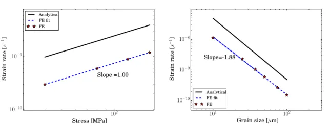
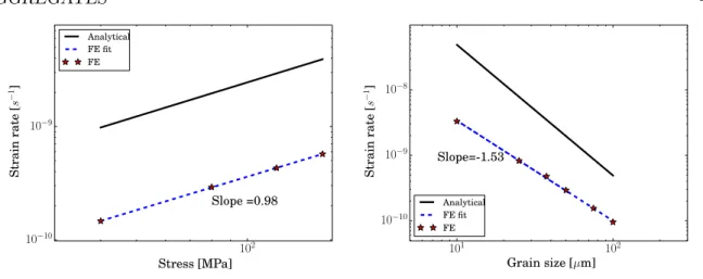
The model is then implemented numerically using the finite elements method. Simulations of biaxial creep of polycrystalline aggregates coupled with vacancy diffusion are performed for the first time, and predict strongly heterogeneous viscoplastic strain fields. The classical macroscopic strain rate dependence on the stress and grain size is also retrieved. Void denuded zones close to the multilayer interfaces are obtained in irradiation simulations of a multilayer, in agreement with experimental observations. Finally, tensile tests of Cu-Nb multilayers are simulated in 3D, where it is shown that the effect of elastic anisotropy is negligible, and evidencing a complex deformation mode.
Keywords: stress-diffusion coupling, creep, voids, Cahn-Hilliard, multilayers, irradiation. i
Preface
Le jour est court, le travail est grand et les travailleurs sont paresseux, mais la r´ecompense est immense et notre maˆıtre nous exhorte `a nous hˆater. Frank Herbert
La citation, qui aurait pu ˆetre de Samuel, est l’œuvre de mon auteur de science fiction pr´ef´er´e, et convient tout `a fait `a l’ouvrage de SF qu’est ce manuscrit. Il est bien ´evident qu’elle est `a prendre au second degr´e; du moins, concernant la r´ecompense. Samuel r´ep`ete toujours, `a juste titre, que ce qu’on fait est “tout `a fait passionnant”. Je suis bien d’accord, mˆeme si certains de ses th´esards, moi en tˆete, semblons nous acharner `a le d´emotiver par nos pitreries et nos ´elucubrations sans queue ni tˆete.
Merci mille fois donc, Samuel, pour m’avoir support´e pendant 3 ans, pour avoir partag´e vos connaissances, pour m’avoir appris `a me faire mieux comprendre lors des pr´esentations, et pour m’avoir donn´e un aper¸cu du monde de la recherche. J’esp`ere sinc`erement garder le contact pour de futurs travaux. Je remercie grandement Esteban pour ses conseils avis´es, ses relectures attentives, et pour m’avoir permis d’am´eliorer mon cot´e relationnel. Je n’aurai pas pu participer `
a un projet Europ´een sans vous.
J’ai eu la chance, pendant ces derni`eres ann´ees, d’avoir pu cˆotoyer les chercheurs du centre, mais aussi d’ailleurs. En particulier, Benoˆıt Appolaire, dont j’appr´ecie l’humour et le franc parler autant que le savoir-faire, et Marc Geers, qui a toujours su me consacrer un peu de son temps et m’a permis de travailler sur des sujets compl´ementaires tr`es int´eressants.
Il y a ´egalement dans cette th`ese beaucoup de Victor de Rancourt, le binˆome id´eal, toujours prˆet `a d´ebattre de n’importe quel probl`eme, `a me faire perdre mon temps sur des questions farfelues, et `a m’en faire gagner en r´epondant aux miennes.
Et puis, p`ele mˆele, merci `a tout les autres: Djamel, Kais et Nikola¨ı, sans qui Zebulon aurait eu ma peau; mes compagnons de bagne en B127, toujours prˆets `a creuser avec nous quand on touchait le fond; Arina, et sa langue bien pendue; Vlad, toujours humble et prˆet `a aider ; Marie-H´el`ene Berger, pour avoir choisi une formidable stagiaire; et tous ceux qui ont contribu´e `
a cette th`ese de pr`es ou de loin.
Contents
Abstract i Preface iii Contents v 1 Introduction 1 1.1 Context . . . 21.2 The Radinterfaces project . . . 4
1.3 Objectives . . . 6
1.4 Methodology . . . 7
1.5 Outline . . . 8
1.6 General notation . . . 9
2 Stress diffusion coupling 11 2.1 Introduction . . . 13
2.2 Continuum thermodynamic coupled diffusion-stress theory . . . 14
2.2.1 Balance equations . . . 14
2.2.2 Constitutive equations . . . 14
2.2.3 Equilibrium composition field . . . 17
2.3 Finite element implementation of the coupled formulation . . . 19
2.4 Analytical and numerical solutions to some boundary values problems . . . 21
2.4.1 Rotating disc . . . 21
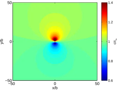
2.4.2 Vacancy diffusion around the core of an edge dislocation . . . 23
2.4.3 Perforated plate subject to a far-field tensile stress . . . 26
2.5 Conclusions . . . 28
3 Field theory and simulation of creep in polycrystalline aggregates 31 3.1 Introduction . . . 33
3.2 Kinetics of vacancy diffusion induced creep in crystals . . . 34
3.2.1 Definition of a material point in the presence of diffusion . . . 34 v
3.2.4 Linearized theory . . . 38
3.3 Balance laws and constitutive equations in elasto-viscoplasticity . . . 38
3.3.1 Balance laws . . . 38
3.3.2 Constitutive equations . . . 38
3.4 Simulation of diffusional creep in a polycrystalline aggregates . . . 40
3.4.1 Grain boundary description . . . 40
3.4.2 Problem description . . . 43
3.4.3 Results . . . 44
3.5 Conclusions . . . 52
4 Modeling radiation damage: a stress-diffusion - Cahn-Hilliard framework 53 4.1 Introduction . . . 55
4.2 The Cahn-Hilliard equation . . . 56
4.3 Choice of homogeneous free energy . . . 58
4.3.1 Polynomial energy . . . 59
4.3.2 Logarithmic form . . . 60
4.4 Choice of mobility . . . 60
4.4.1 Summary . . . 62
4.5 Elementary solutions to the Cahn Hilliard equations . . . 62
4.5.1 Identification of interface width and energy . . . 62
4.5.2 Critical wavelength . . . 66
4.6 Application of the micromorphic approach to the Cahn-Hilliard equation . . . 67
4.7 Stress-diffusion coupled Cahn-Hilliard framework for nuclear reactors applications 68 4.7.1 Balance laws . . . 69
4.7.2 Constitutive equations . . . 69
4.8 Choice of parameters . . . 73
4.9 Single void growth . . . 76
4.10 Damage evolution in an irradiated Fe polycrystal . . . 78
4.11 Concluding remarks and future work . . . 78
5 Mechanical and irradiation behaviour of nano-crystalline multilayers 83 5.1 Introduction . . . 85
5.2 Modeling approach . . . 87
5.3 Application: mechanical behaviour of Cu-Nb systems . . . 89
5.3.1 Interface orientation relationship influence on the macroscopic mechanical behaviour . . . 89
5.3.2 Effect of elastic anisotropy . . . 94
5.3.3 Hard and shearable interfaces . . . 96
5.4 Void nucleation and evolution under irradiation . . . 98
5.5 Conclusions and recommendations for future work . . . 99
6 Conclusions and prospects for future work 103 6.1 Coupling stress, strain, and diffusion of point defects . . . 104
6.2 Void nucleation and growth in irradiated crystalline materials . . . 105
6.3 Mechanical behaviour of Cu-Nb multilayers . . . 106
CONTENTS vii
A Derivation of open system elastic constants 109
B Finite element derivatives 111
B.1 Terms Ku X . . . 111
B.2 Terms KciX . . . 111
B.3 Terms KcvX . . . 112
B.4 Terms KcχX . . . 112
C Cahn Hilliard framework 115 C.1 Normalisation . . . 115
C.2 Derivatives needed for numerical implementation . . . 116
C.2.1 Diffusion potential . . . 116 C.2.2 Free energy . . . 119 C.2.3 Misc . . . 121 D Code samples 123 Bibliography 125 Index 137
Chapter
1
Introduction
R´
esum´
e
Entre 2005 et 2020, la demande ´energ´etique aura crˆu de 50%, satisfaite en grande partie grˆace aux ´energies fossiles. L’´energie nucl´eaire, fission ou fusion, repr´esente une part importante du mix ´energ´etique du futur. Dans ces centrales, les mat´eriaux subissent des conditions de service extrˆemes: tr`es haute pression et temp´erature, corrosion, irradiation. De la g´en´eration III `a la g´en´eration IV, ces conditions ne feront qu’empirer: la temp´erature maximum passera de 325◦C `
a 600◦C, la dose d’irradiation doublera, etc. Le coeur du r´eacteur ne peut ˆetre remplac´e et conditionne donc la dur´ee de vie de toute la centrale.
L’endommagement par irradiation commence toujours avec la cr´eation de d´efauts ponctuels, tels que les lacunes et les auto-interstitiels, g´en´er´es par les collisions entre les atomes du r´eseau cristallin et les particules ´energ´etiques incidentes (h´elium, neutrons, . . . ). Ces d´efauts diffusent dans le mat´eriau, et s’agr`egent en structures 2D et 3D, modifiant consid´erablement ses pro-pri´et´es, provoquant fluage, gonflement, et fragilisation. La dose d’irradiation s’exprime souvent en d´eplacements par atome: 40 dpa pendant 40 ans signifie qu’au cours de cette p´eriode chaque atome aura ´et´e d´eplac´e 40 fois.
La vocation premi`ere des mat´eriaux pour le nucl´eaire est donc d’offrir des capacit´es de tol´erance `a l’irradiation importante. L’´emergence de nouveaux concepts, s’appuyant sur les nanotechnologies, promet d’augmenter ces capacit´es de mani`ere significative. Du fait d’une haute densit´e d’interface, ces nano-mat´eriaux sont capables de s’auto-r´eparer et de pi´eger les d´efauts d’irradiation, ralentissant consid´erablement l’endommagement. L’approche pr´esent´ee dans cette th`ese s’inscrit dans le projet Europ´een Radinterfaces, dont l’objectif est d’´etudier et caract´eriser le comportement sous irradiation de multi-couches nanom´etriques, via une ap-proche multi-´echelle. Les objectifs de cette th`ese sont, dans le cadre de la m´ecanique des milieux continus, les suivants:
• Les d´efauts ponctuels sont les premiers types de d´efauts d’irradiation. Il est donc critique de mod´eliser pr´ecis´ement leur diffusion dans un champ de contraintes h´et´erog`ene, dans un mat´eriau complexe.
d´etaill´ee du champ de d´eformation dans un polycristal.
• Du fait de leur densit´e d’interface ´elev´ee, les m´echanismes de d´eformation des nano-mat´eriaux sont souvent pilot´es par les interactions entre les interfaces et les d´efauts 1D, 2D, et 3D. Il est donc n´ecessaire d’´etudier comment le type d’interface et l’orientation relative des cristaux influencent la r´esistance m´ecanique.
• Enfin, si le mat´eriau est incapable d’´evacuer les d´efauts ponctuels suffisamment vite, ceux-ci se rassemblent en clusters et cavit´es. Un cadre thermodynamique est donc mis en place afin d’identifier les propri´et´es du nano-mat´eriau permettant de retarder au mieux ces ph´enom`enes d´el´et`eres.
Dans l’approche consid´er´ee dans cette th`ese, la microstructure est explicitement mod´elis´ee, afin de traiter au mieux l’interaction d´efauts/interfaces. De plus, il est connu que la force motrice pour la diffusion est fortement affect´ee par les joints de grains, via un couplage chimie-m´ecanique. Leur mod´elisation explicite permet donc d’obtenir un flux de lacunes, et donc une d´eformation de fluage, r´ealiste dans le polycristal. Le mod`ele vient combler un foss´e pr´esent dans la litt´erature, dont les travaux soit n´egligeaient le caract`ere coupl´e de la force motrice, soit limitaient la d´eformation de fluage aux joints de grains. Le cadre de mod´elisation est ensuite ´etendu afin de prendre en compte l’interaction entre les d´efauts d’irradiation, ainsi que la formation de cavit´es via un mod`ele de type Cahn-Hilliard, coupl´e `a la plasticit´e
cristalline.
Contents
1.1 Context . . . 2
1.2 The Radinterfaces project . . . 4
1.3 Objectives . . . 6
1.4 Methodology . . . 7
1.5 Outline . . . 8
1.6 General notation . . . 9
1.1
Context
The need for energy in the world is ever-growing, +50% from 2005 to 2020, and will be mainly satisfied by fossil fuel in the near future [73]. However, nuclear power is considered as an important part of the energetic mix, taking into account efficiency and environmental impact. In these power plants, materials experience harsh service conditions: extreme pressure, thermal and chemical loading, and irradiation damage. Components have to preserve their integrity during the lifetime of the plant, typically planned initially 40 years. Those situated inside the concrete containment building, fig. 1.1, will sustain large irradiation dose [13].
In the generation III Pressurised Water Reactor (PWR), the reactor fuel is either uranium or plutonium. It is usually made up of low alloy steels, 20 cm thick, coated by a 5mm thin stainless steel to prevent corrosion. The core of the pressure vessel is cooled by the primary water circuit, with internal pressure of up to 150 bars. The water temperature is approximately
1.1. CONTEXT 3
Figure 1.1: Schematic layout of a typical pressurised water reactor [34]
290◦C at the entrance to the reactor itself and 325◦C at the exit. The reactor pressure vessel cannot be replaced, and hence controls the lifetime of the plant.
Irradiation damage starts with the production of point defects in the material, such as vacancies and self interstitials, due to the collision of lattice atoms by an incident energetic particle (neutron, helium, etc). These defects then cluster to form 2D and 3D structures, such as dislocation loops and voids. Macroscopically, this leads to void swelling and irradiation creep. As all types of lattice disorder, irradiation damage impedes or slows down the motion of dislocations. This results in an increase in the material strength and a decrease in its ductility. This embrittlement leads to a decrease in the critical principal stress at which brittle fracture can occur at a given temperature. In the nuclear industry, the empirical criteria for embrittlement rely on the reference temperature, defined as the temperature at which the material begins to exhibit a transitional behaviour from brittle to ductile [23]. During irradiation, this temperature increases; if it approaches the service temperature of the component, there is a risk of failure. The evolution of this transition temperature is calculated empirically as a function of the chemical elements in the steel linked to either impurities or reacting elements, the temperature and the maximum accumulated radiation dose [115]. The accumulated radiation dose is often expressed in displacement per atom (dpa). The notion of dpa quantifies the structural effects of elastic collisions, and is defined as the number of times where atoms have been ejected from their stable sites as a result of neutron collisions. The pressure vessel can reach 40 dpa over 40 years: this means that, in average, each atom has been displaced 40 times. Furthermore, some physical phenomena, mainly diffusion related ones, depend not only on the dpa but also on the dpa rate. Several technical solutions are being studied for the future generation of nuclear reactors (IV), which have to satisfy several criteria such as enhanced safety, waste minimisation and better economic efficiency. In PWR, only about 5% of the fuel is consumed before being replaced and removed from the reactor [73], which is different in a fast neutron reactors. In France, efforts
compared to PWR, are as follows:
• the distance from the fuel assembly to the pressure vessel walls is larger, hence leading to an almost negligible level of irradiation.
• the service temperature ranges from 350◦C in the primary circuit, to 650◦C in the fuel
assembly.
The design in the fuel pin has to be modified so as to minimise swelling since combustion rates will be relatively high (i.e. 100 dpa over 10 years). For the generation IV reactors, the main materials being considered are 316L steel, Ni alloys, oxide dispersed strengthening alloys, and 9% Cr steel. However, due to the high irradiation loads in the fuel assembly and relatively high temperatures, it is of crucial importance to explore alternative original material solutions.
1.2
The Radinterfaces project
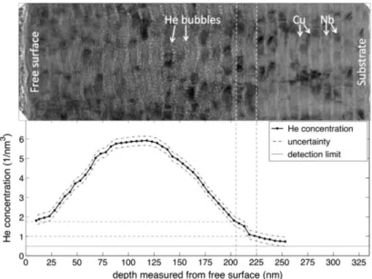
A common goal for materials in nuclear reactors, like containment vessels or fuel cladding ma-terials, is to exhibit the highest radiation tolerance. The emergence of new concepts using nanoscience in the design of bulk structural materials shows potential for providing the break-throughs needed for future nuclear energy systems. Regardless of the type of reactor (fusion or fission), and its generation, the irradiation damage first appears as point defects within the material: vacancies, self interstitial atoms (denoted SIA), or extrinsic defects such as hydrogen or helium. New advances in nano sciences allow for the design of self-healing materials, in par-ticular, carefully constructed interfaces have the potential to absorb defects, see for example He in Cu-Nb multilayers in fig. 1.2 [17, 59, 70]. If points defects are prevented from clustering,
Figure 1.2: A comparison between the TEM micrograph of a He3-implanted Cu–Nb multilayer (top) and the corresponding He concentration profile measured by Nuclear Reaction Analysis (bottom) reveals a critical depth at which no He bubbles are observed (indicated by dashed lines), even though the He concentration is not zero. [38]
1.2. THE RADINTERFACES PROJECT 5
extending the lifetime of the component. In order to unlock the full potential of nanoscience in designing materials for nuclear systems, it is necessary to develop an extensive physical and chemical understanding of defect production, diffusion, and trapping under extreme conditions of temperature, radiation, and stresses. Theory, modelling and simulation tools can provide de-tailed understanding and predictive capabilities for nanostructured functional materials applied to nuclear energy systems.
The study of such materials is by nature multiscale, both in time and space: the initial irradiation cascade lasts only a few picoseconds and is extremely localised, whereas the processes leading to creep and void swelling can take months and lead to large volume change in a reactor component. It is then necessary to understand the physics behind all these processes, starting from point defect production and diffusion, to void growth and mechanical failure. At each scale, physically sound parameters need to be determined and passed on to the upper scales, from atomistic to continuum mechanics, assisted by experimental observations.
The approach to be developed in this thesis will be applied to nanoscale metallic multilayer composites, whose interfaces have been studied extensively in the past few years, both exper-imentally and theoretically, with promising results [21, 124, 78]. The interfaces between two neighboring alloys has been observed to be preferential recombination zones for point defects. Since the density of interfaces in these nanomaterials is very high, this effectively allows for self-healing. Moreover, interfaces also modify the behaviour of dislocations in the layer, which may lead to outstanding mechanical properties.
The present PhD work is part of the European Radinterfaces project, involving nine uni-versities, fig. 1.3, which aims to control radiation damage in nanocrystalline materials through interface design using multiscale modelling concepts and techniques. The project was part of the seventh framework programme, and addressed the call “Modelling of degradation and reliability of crystalline materials”.
Figure 1.3: Academic partners of the Radinterfaces consortium
The multiphysics approach developed in the European project combined density functional theory (DFT) to characterise the interface structure at the electronic level, molecular dynamics, kinetic Monte Carlo and dislocation dynamics to study defect interactions at the atomistic and defect level, and continuum approaches to study void evolution and mechanical behaviour at the
radiation damage, using OKMC simulations, were realised by the IMDEA, the Polytechnic University of Madrid, and the University of Oviedo. The development of the multiphysics meso-scale framework predicting the evolution and effects of the irradiation damage was carried out by GeorgiaTech Lorraine and the Ecole des Mines de Paris. Finally, the multilayer processing and characterisation was assigned to the IMDEA and the Universities of Cagliari and Prague. An example of voids observed by the IMDEA team in a Cu-Nb sample is shown in fig. 1.4.
Figure 1.4: Voids in the copper layer of a Cu-Nb sample obtained by physical vapor deposition, observed by the IMDEA team by TEM after 1 dpa.
1.3
Objectives
The present work is focused on the meso and nano-scales. A continuum modelling framework is developed to predict the evolution of the irradiation damage and the material behaviour. The objectives are as follows.
• Point defects are the primary type of defects produced by irradiation damage. It is thus critical to model accurately their motion in complex material systems operating under severe loading and environmental conditions. The first objective is then to derive a con-tinuum stress-diffusion coupled framework at the macro and meso scale.
• As stated previously, irradiation produces many point defects, in particular, vacancies, whose diffusion leads to creep. In crystalline metallic materials, the driving force for vacancy diffusion is the difference between chemical potentials in the grain boundaries.The second objective of this work is thus to describe strain fields inside the grains arising from diffusion processes and dislocation slip in a polycrystal subjected to a constant applied mechanical load.
1.4. METHODOLOGY 7 • In nanoscale materials, the density of interfaces is very high, and the macroscopic mechan-ical behaviour is driven by interface processes. For instance, dislocation glide and climb is strongly impacted by the nanoscale features of the microstructure. It is necessary inves-tigate how the type of interface and the orientation of the crystals affect the mechanical resistance, in order to obtain the desired system properties.
• If the multilayer is unable to evacuate or recombine point defects at a sufficient rate, the defects form clusters and voids. It is then necessary to identify the multilayer properties leading to the best lifetime, such as interface orientation relationship, layer thickness, etc. The last objective is to develop a continuum framework to describe evolution of self interstitials and vacancies, and their interactions with interfaces, as well as void nucleation and growth in a multilayer.
1.4
Methodology
Most deleterious effects of irradiation on material properties - e.g. void swelling, irradiation creep, radiation-induced hardening and embrittlement - can be traced back to the formation and migration of the aforementioned point defects. It is well known that stresses influence the diffusion of point defects, and vice versa. The larger the inhomogeneities in stresses, the larger their influence on diffusion. The Cottrell atmospheres, which consist of the redistribution of point defects around a dislocation, is a well known example [64]. Recently, Cahn [25] published a paper on these atmospheres, to “correct the misconception in the literature that the solute distribution does not affect the stress field of the dislocation”.
It is then critical to lay out a fundamental thermodynamic framework, coupling stress and diffusion, on which to base the work of this thesis. Podstrigach and coworkers [101] were the first to develop a thermodynamic theory of stress diffusion coupling, relying on the choice of a free energy. Analytical solutions were proposed for a loaded plate with a void [102] and a bended plate [98]. Cahn and Larch´e [27] later developed a coupled stress-diffusion theory, where the coupling came from the mechanical constitutive laws. Indeed, the use of a concentration-dependent eigenstrain gives rise to a stress-dependent diffusion potential. Furthermore, Cahn and Larch´e presented a systematic procedure to solve stress diffusion coupled problems, provided an elastic behaviour was considered. It relies on open system elastic constants, or elastic constants derived at constant diffusion potential, in order to obtain a linearised version of the non-linear coupled problem. It is the latter approach that is developed in the work, and extended to elasto-viscoplastic behaviour, using internal variable concepts [16].
The previous framework describes the migration of point defects in a heterogeneous stress field, but their contribution to the deformation is reversible, while the diffusion of vacancies at high temperatures is known to induce creep deformation [63]. The associated driving force in polycrystals is the difference of the diffusion potential from one grain boundary to another, which is modified by the normal traction on the corresponding grain boundary surfaces. This is of interest for the present nanolayered material since the grain boundary volume fraction is large and since they are expected to operate at high temperatures. Furthermore, a detailed description of the grain boundary is necessary to accurately describe their interaction with radiation induced defects. It has been shown by molecular dynamics simulations that grain boundaries play a critical role in defects recombination [99, 106, 8, 60]. Hence, the previous framework will be extended to account for diffusion creep in an original and detailed manner. The work is conducted at the mesoscale, with an explicit geometrical description of grain and grain boundaries in order to model the change of diffusion potential at grain boundaries, and hence the vacancy diffusion driving force. Then, the viscoplastic deformation rate will be shown
[56, 117], or were confining the strain to the grain boundary region [14, 49]. The present model addresses these gaps, and enables the description of deformation fields inside the grains arising from diffusion processes and dislocation slip in a polycrystal subjected to constant applied loads. Up to this point, the proposed framework describes the point defects migration, with a strong coupling with stress. The natural next step is then to describe the formation of voids when the vacancy concentration becomes larger than a critical value. Phase field methods have proven useful for that purpose [105, 87], along with modified point defects balance equations to account for irradiation effects. Such phase field models have also been used to simulate the void denuded zones close to grain boundaries [86, 7]. However, previous work lack an explicit mechanical coupling with the stress. For instance in [11], it was proposed that, during creep, voids grow by receiving stress-driven vacancy fluxes from nearby grain boundary sources. The presently proposed framework, with its detailed description of grain boundaries, can then be complemented by a phase field model to study the influence of stress on the growth kinetics of voids.
Finally, nanoscale multilayers composed of alternate layers of two immiscible metals are considered. In such materials, the macroscopic behaviour is mainly driven by the interfaces between each layer [78, 59]. In the literature, most of the effort has been focused on experimental techniques and atomistic scale modelling, see for instance [18, 79]. Here, a continuum approach is followed at the nanoscale, whereby a diffuse interface-affected zone with specific properties is defined. Regarding mechanical properties, as molecular dynamics simulations reveal significant dislocation core spreading at interfaces [108], the latter are defined in the continuum model as a dislocation sink. Furthermore, the interface is treated as a crystallographic slip plane to model its shearable character [123]. Concerning interface interaction with point defects, the interface affected zone is modeled as a preferential defect recombination zone [70, 76].
1.5
Outline
The thesis is divided in four chapters, each corresponding to one of the above mentioned objec-tives.
First, a stress-diffusion coupled framework is presented in Chapter 2 based on the Cahn and Larch´e approach, complemented by the introduction of internal variables necessary to address plasticity. The model is implemented numerically into a finite element code and used to solve three boundary value problems. The numerical solutions are validated against analytical ones, and the influence of plasticity on the defect distribution is discussed.
Next, in Chapter 3, the creep kinetics is formulated. The diffusion creep strain-rate tensor is derived as the deviatoric symmetric part of the gradient of the vacancy flux. A crystal plasticity model is used to describe the inelastic strain arising from dislocation glide and climb. Then, a coupled framework, retrieving Herring Nabarro’s diffusion relation, is presented and used to predict creep behaviour of a polycrystal. The numerical results are in good agreement with the experimental ones, and detailed deformation fields inside the grains are obtained.
In order to model void nucleation and growth, a Cahn-Hilliard based framework is proposed in Chapter 4 and implemented numerically using a micromorphic approach [46]. The diffusion equations are modified to account for point defects recombination and evacuation in sinks such as interfaces. The stress diffusion couplings developed in the previous chapter are included in the framework, leading to a modified Cahn-Hilliard equation, where the kinetics is influenced by elastic energy in the solid. Two applications are presented: the point defect evolution in a
1.6. GENERAL NOTATION 9
polycrystal is studied first, using constant or dose dependent material parameters obtained by cluster dynamics simulation. Then, the influence of mechanical coupling on the growth kinetics of a void is investigated.
Finally, in Chapter 5, the mechanical behaviour and resistance to irradiation of nano mul-tilayers is investigated. Simulations using the finite element method are performed to compare the hard and shearable interface models in terms of macroscopic stress strain curves on Cu-Nb systems. Using the Cahn-Hilliard model developed in Chapter 4, the irradiation of a generic bilayer is simulated. Void nucleation and growth is observed in the bulk, while the interface affected zone remains void free. This model is combined with the previously developed stress diffusion coupled phase field framework to study the behaviour of an irradiated Cu-Nb bilayer.
1.6
General notation
A Cartesian coordinate system, with unit vectors e1, e2, e3, is used throughout the manuscript, unless specified otherwise. Following the Einstein summation convention, repeated indices are summed. The following notations are generally used in the present work.
Scalar a
Vector v
Second order tensor σ∼
Fourth order tensor C∼
∼ Tensor product c = a · b = aibi Open product ∼c= a ⊗ b = aibjei⊗ ej = cijei⊗ ej Concentration fields ci, cv, . . . Fluxes Ji, Jv,. . . Generalized stresses π, ξ Displacement u Strain tensors ε∼
Chapter
2
Stress diffusion coupling
Most deleterious effects of irradiation on material properties - e.g. void swelling, irradiation creep, radiation-induced hardening and embrittlement - can be traced back to the formation and migration of the point defects. It is well known that stresses influence the diffusion of point defects, but the effect of point defects on the stress field is often neglected. It is critical to lay out a fundamental thermodynamic framework, coupling stress and diffusion, on which to base the work of this thesis. This chapter is reproduced from [120].R´
esum´
e
Un cadre thermodynamique couplant la m´ecanique non lin´eaire et la diffusion est propos´e et impl´ement´e num´eriquement via la m´ethode des ´el´ements finis. Celle-ci est valid´ee sur des so-lutions analytiques, reposant sur la m´ethode de Cahn et Larch´e ´etendue `a la plasticit´e. Une attention particuli`ere est donn´ee aux constantes ´elastiques `a systeme ouvert, i.e. celles d´eriv´ees `
a potentiel de diffusion constant, puisqu’elles permettent d’obtenir la solution du probl`eme coupl´e complet uniquement `a partir d’une solution ´elastique ´equivalente. Enfin, les effets de la plasticit´e sur l’´equilibre global du syst`eme sont discut´es.
Summary
A macroscopic coupled stress-diffusion theory which account for the effects of non-linear material behaviour, based on the framework proposed by Cahn and Larch´e, is presented and implemented numerically into the finite element method. The numerical implementation is validated against analytical solutions for different boundary valued problems. Particular attention is paid to the open system elastic constants, i.e. those derived at constant diffusion potential, since they enable the equilibrium composition field for any generic chemical-mechanical coupled problem to be obtained through the solution of an equivalent elastic problem. Finally, the effects of plasticity on the overall equilibrium state of the coupled problem solution are discussed.
Contents
2.1 Introduction . . . 13
2.2 Continuum thermodynamic coupled diffusion-stress theory . . . 14
2.2.1 Balance equations . . . 14 2.2.2 Constitutive equations . . . 14 2.2.2.1 General theory . . . 14 2.2.2.2 Choice of potential and energy functions . . . 16 2.2.3 Equilibrium composition field . . . 17 2.2.3.1 Theory . . . 17 2.2.3.2 Methodology for deriving analytical solutions of a
stress-diffusion coupled problem . . . 19 2.3 Finite element implementation of the coupled formulation . . . 19
2.4 Analytical and numerical solutions to some boundary values problems . . . 21
2.4.1 Rotating disc . . . 21 2.4.2 Vacancy diffusion around the core of an edge dislocation . . . 23 2.4.3 Perforated plate subject to a far-field tensile stress . . . 26 2.5 Conclusions . . . 28
2.1. INTRODUCTION 13
2.1
Introduction
Problems involving diffusion in a stressed material system can be found in numerous applications generally concerned with high homologous temperatures, such as thin films in semiconductor devices and power plant and aero-engine components. The transport of matter by diffusion under stress can generally result in the gradual degradation of the material microstructure, leading to the nucleation of local damage (e.g., stable vacancy clusters or micro-voids, micro-cracks). The presence of such local damage events could impede the correct performance of the component or device and limit its targeted service life. It is thus critical to model accurately the motion of diffusing species and point defects in complex material systems operating under severe loading and environmental conditions.
Podstrigach and coworkers [101] were the first to develop as thermodynamic theory of stress diffusion coupling. It relies on the choice of a free energy, and analytical solutions are proposed for a loaded plate with a void [102] and a bended plate [98]. Cahn and Larch´e [27] later devel-oped a coupled stress-diffusion theory, where the coupling came from the mechanical constitutive laws. In their thermodynamic theory (see [28] for full details, and [9] for a broad discussion), the convenient concept of network is introduced, whereby all atoms are assumed to be capable of diffusing. In a crystal, for instance, the lattice itself can be assumed to act as the network and to remain coherent. Equilibrium can then be attained by considering a constant and ho-mogeneous diffusion potential. Cahn and Larch´e also introduced the concept of open system elastic constants, or elastic constants derived at constant diffusion potential, in order to obtain a linearised version of the non-linear coupled problem. Maugin [80] also addressed extensively the thermodynamic problem of a diffusive variable, without stress-coupling, albeit considering the first gradient of the concentration as well.
Other approaches have been used to model specific problems involving the coupling between stress and diffusion. For instance, the diffusion of vacancies within the heterogeneous stress field around an edge dislocation core has been treated in [104] using Bessel functions. In con-trast, boundary value problems involving coupled diffusion-stress phenomena have been solved analytically using Cosserat spectrum theory in [97]. In [130] and [131], finite element solutions involving stress-induced diffusion in a plate subject to different types of boundary conditions were reported. In [116], the authors relied on Lambert functions to derive an analytical solution of the chemical concentration in a loaded rod, and compared it to a coupled finite element for-mulation. Finally, Anand [6] developed a thermodynamical theory which accounts for diffusion of hydrogen and heat coupled with the mechanical problem.
The theory is implemented numerically using the finite element method and used to solve three elastic and elasto-plastic stress-diffusion boundary value problems, out of which two were never addressed in the literature before. The first one involves a coupled diffusion-stress for-mulation for a disc rotating at high speeds and temperature, i.e. at conditions similar to those encountered in gas turbine engine components. The second concerns the classical redistribution of vacancies around an edge dislocation, as described in [64], which can be related to a recent paper by Cahn [25]. Finally, a problem relevant to vacancy diffusion-driven cavitation in nuclear reactor components is studied, i.e. the redistribution of vacancies in a loaded perforated plate, influenced by plasticity.
The objective of the present paper is to provide a validation of the fully coupled implementa-tion against the systematic analytical soluimplementa-tion given by Cahn and Larch´e, complemented by the introduction of internal variables necessary to address plasticity. The introduction of plasticity in the constitutive equations allows for a direct extension of the solution of Cahn and Larch´e, given for an elastic behaviour. If the stress diffusion coupling had been dependant on the choice of free energy, it would have been less straightforward to obtain coupled analytical solution for
can be derived.
2.2
Continuum thermodynamic coupled diffusion-stress theory
2.2.1 Balance equations
The diffusing species are assumed to be solute atoms and vacancies. Their concentration obeys the mass balance equation, which relates the concentration, c, to the flux vector, J ,
˙c =−div J on V
j = J · n on ∂V (2.1)
where no source term is considered. The concentration is defined as the ratio between the lattice sites occupied by solute atoms or vacancies and the total number of lattice sites in the crystalline solid. The mechanical static equilibrium is defined by:
div σ∼+ f = 0 on V
t = σ∼· n on ∂V (2.2)
where σ∼ is the stress tensor, f is the body force vector in V and t the traction vector acting on ∂V .
2.2.2 Constitutive equations
2.2.2.1 General theory The total strain is partitioned as:
ε ∼= ε∼ e+ ε ∼ p+ ε ∼ ⋆(c) (2.3)
where ε∼e is the elastic strain tensor, ε∼p the plastic strain tensor , and ε∼⋆ the eigenstrain tensor, representing the volume change associated with the substitution of species in lattice sites. The latter typically depends on the concentration , c, as
ε
∼
⋆(c) = (c− c
ref)η∼+ ε∼⋆ref . (2.4)
Here, ε∼⋆,ref is the eigenstrain tensor corresponding to the reference concentration, cref, and the
tensor η ∼=
∂ε∼
∂c scales the concentration change. Recall the first law of thermodynamics: ∫ V ˙edV = ∫ V σ∼ : ˙ε∼dV (2.5)
where, e, is the internal energy density per unit volume and σ∼ the stress tensor. The second
law states that: ∫
V ˙sdV − ∫ ∂V µJ T · n dS ≥ 0 (2.6)
where, s, is the entropy density, T, the absolute temperature, and µ the diffusion potential1. The local form of the second law (2.6), for constant temperature, reads:
T ˙s− div (µJ ) ≥ 0 (2.7)
1
In the sense of Cahn and Larch´e: µ = µs− µh, where µs is the chemical potential of the species under consideration, and µhis the chemical potential of the host atoms
2.2. CONTINUUM THERMODYNAMIC COUPLED DIFFUSION-STRESS THEORY 15
Recalling ψ = e− T s, the free energy density per unit volume at constant temperature, then equation (2.7) yields the local form of the dissipation inequality:
D = σ∼ : ˙ε∼− div (µJ ) − ˙ψ ≥ 0 (2.8)
Here, the free energy volumetric density function is assumed to consist of a mechanical and a chemical part, which depend on several independent state variables, i.e. the elastic strain tensor
ε
∼e, an isotropic scalar hardening variable r, a traceless kinematic tensorial hardening variable,
α∼ [72], and the vacancy concentration, c. Then,
ψ(ε∼e, r, α∼, c) = ψmech(∼εe, r, α∼, c)+ ψchem(c). (2.9) The mechanical part of the free energy is defined as,
ψmech(ε∼e, r, α∼, c)= 1 2ε∼ e: Λ ∼∼(c) : ε∼ e+ ψmech,p(r, α ∼, c ) , (2.10)
where Λ is elastic moduli fourth order tensor, and ψmech,p(r, α∼, c) corresponds to the energy stored by work-hardening. The dissipation can then be expressed in terms of equations (2.8), (2.1) and (2.9) as: D = ( σ∼− ∂ψ ∂ε∼e ) : ˙ε∼e + ( µ + σ∼ : η ∼− ∂ψ ∂c ) ˙c − j · ∇ µ + σ∼ : ˙ε∼p−∂ψ ∂r ˙r− ∂ψ ∂α∼ : ˙α∼ ≥ 0 (2.11) The condition (2.11) depends linearly on the independent variables ˙ϵ∼e, ˙c, and the terms in brackets are independent of ˙ϵ∼e and ˙c. The state laws then follow for the stress and diffusion potential (Coleman-Noll argument):
σ∼ = ∂ψ
∂ε∼e, (2.12)
and the diffusion potential,
µ = ∂ψ
∂c − σ∼: η∼, (2.13)
The following thermodynamic forces can be inferred from equation (2.11). Thus, Rp =
∂ψ
∂r , X =
∂ψ
∂α∼ (2.14)
The dissipation inequality then simplifies to:
−j · ∇ µ + σ∼: ˙ε∼p− Rp˙r− X∼ : ˙α∼ ≥ 0 (2.15)
To ensure positiveness of the dissipation, the existence of a convex dissipation potential Ω(σ∼, Rp, X∼,∇ µ),
is assumed so that : ˙r =−∂Ω ∂Rp , α∼˙ =−∂Ω ∂X , ∼˙ε p = ∂Ω ∂σ∼ , j =− ∂Ω ∂∇ µ (2.16) In the case of rate-independent plasticity, which is of practical interest here for enabling analyt-ical solutions, two distinct potentials, Ωmech and Ωchem, are introduced such that
˙r =− ˙λ∂Ω mech ∂Rp , α∼˙ =− ˙λ∂Ω mech ∂X , ∼˙ε p = ˙λ∂Ωmech ∂σ∼ , j =− ∂Ωchem ∂∇ µ (2.17)
≥ 0, g ≤ 0. The consistency condition under plastic loading reads: ˙g = 0 = ∂g ∂σ∼ : ˙σ∼+ ∂g ∂X : ˙X + ∂g ∂Rp ˙ Rp , (2.18)
from which the plastic multiplier is obtained,
˙λ = ∂g ∂σ∼ : ∂2ψ ∂ε∼e2 : ˙ε∼+ ( ∂g ∂σ∼ : ∂2ψ ∂ε∼e∂c ) ˙c ∂g ∂σ∼ : ∂2ψ ∂ε∼e2 : ∂Ωmech ∂σ∼ + ∂g ∂Rp ∂2ψ ∂r2 ∂Ωmech ∂Rp + ∂g ∂X∼ : ∂2ψ ∂α∼2 : ∂Ωmech ∂X∼ . (2.19)
In the equation (2.19), ψmech,p is assumed to be independent of c. 2.2.2.2 Choice of potential and energy functions
The chemical free energy component in equation (2.9) is expressed in a standard form [35]: ψchem(c) = Efc
Ω0
+ R T Ω0
(c ln(c) + (1− c) ln(1 − c)) , (2.20) where, Ef, is the formation enthalpy of a mole of the considered species, T, is the absolute
temperature and, R, is the universal gas constant. The tensor η
∼ takes the form η∼= η1∼for the particular case of isotropy, where 1∼is the second order identity tensor and
η = 1 3
∆v Ω0
. (2.21)
In the above equation, ∆v, is the relaxed lattice volume after one mole of atoms is removed from the lattice, and Ω0, the volume occupied by a mole of atoms. Equation (2.4) then becomes,
ε
∼⋆(c) = η(c− cref) 1 + ε∼⋆ref. (2.22)
Finally, the diffusion potential is expressed as: µ = ∂ψ ∂c − σ∼ : η∼= RT Ω0 ( ln ( c 1− c ) + Ef RT ) − η tr(σ∼). (2.23)
Following [72], the plastic term in the free energy (2.10) is taken as: ψmech,p= R∞ ( r + 1 b[exp(−br) − 1] ) + 1 3Cα∼ : α∼ (2.24) where R∞, b and C are material parameters. The thermodynamic forces are expressed from equation (2.14) as: Rp = ∂ψ ∂r = R∞(1− exp(−br)) , X∼ = ∂ψ ∂α∼ = 2 3Cα∼ . (2.25)
The yield function, g(σ∼, X∼, Rp), is defined by:
g(σ∼, X∼, Rp) = σeq− Rp− σy , (2.26)
where σy is the initial yield strength, σeq is the effective equivalent stress, defined as:
J2(σ∼− X∼) =
√ 3 2(σ∼
dev− X
∼dev) : (σ∼dev− X∼dev) (2.27)
2.2. CONTINUUM THERMODYNAMIC COUPLED DIFFUSION-STRESS THEORY 17
For time-dependent plasticity, the dissipation potential is taken to be: Ω(Rp, σ∼,∇ µ) = Ka n + 1 ⟨ g(σ∼, X∼, Rp) Ka ⟩n+1 +1 2L∼(c) :∇ µ ⊗ ∇ µ (2.28) where Ka and n are material parameters. The term < a >= a if a > 0, else < a >= 0.
Using the functions introduced in this section, equation (2.16) becomes : ˙r =− ∂Ω ∂Rp = ⟨ σeq− Rp− σy Ka ⟩n ˙ε ∼ p = ∂Ω ∂σ∼ = ∂Ω ∂σeq ∂σeq ∂σ∼ = 3 2 ⟨ σeq− Rp− σy Ka ⟩nσ ∼dev− X∼ σeq ˙ α∼ =−∂Ω ∂X∼ =− ∂Ω ∂σeq ∂σeq ∂X∼ = 3 2 ⟨ σeq− Rp− σy Ka ⟩n σ∼dev− X∼ σeq = ˙ε∼p (2.29)
For time-independent plasticity, the dissipation potentials considered reads [72]: Ωmech= g(σ∼, X∼, Rp) , Ωchem=
1
2L∼(c) :∇ µ ⊗ ∇ µ, (2.30) The evolution of the plastic internal variable given by equation (2.17) becomes:
˙r =− ˙λ∂Ω mech ∂Rp = ˙λ ˙ε ∼p= ˙λ ∂Ωmech ∂σ∼ = ˙λ 3 2 σ∼dev− X∼dev σeq ˙ α∼ =− ˙λ∂Ω mech ∂X = ˙λ 3 2 σ∼dev− X∼dev σeq = ˙ε∼p (2.31)
It is assumed that, for the isotropic case,
L∼(c) = L(c)1∼= DΩ0
RT c(1− c)1∼, (2.32)
with D being the diffusivity. Then, substitution of equation (2.32) and the gradient of equation (2.23) into equation (2.17) leaves,
j =−D∇ c +1
3 D∆v
RT c(1− c)∇ (tr(σ∼)) (2.33)
Equation (2.33) clearly reveals the two main driving forces controlling the vacancy flux: the concentration gradient term arising from inhomogeneities in the composition, and the mechanical contribution via the stress gradient.
2.2.3 Equilibrium composition field
2.2.3.1 Theory
In this part, it will be shown that, provided that an elastic solution of the purely mechanical problem is known, an equilibrium composition field can be obtained taking the two-way coupling into account. The plastic deformation field, ε∼p, will be assumed to be known in the whole body and to be constant.
alone. An expression for the equilibrium chemical concentration is obtained in terms of the corresponding diffusion potential, µeq, from equation (2.23) assuming that c ≪ 1 For the fully
anisotropic case (where η
≁= η1∼): ceq= exp ( Ω0 RTµeq− Ef RT ) exp ( Ω0 RTη∼: σ∼ ) . (2.34) Let us define ∂µ ∂c σij=0 = 1 χ , (2.35)
Using (2.23) and (2.35) for small values of c implies that χ = Ω0 RTc (2.36) Denoting c0 = exp ( Ω0 RTµeq− Ef RT )
, the composition field is linearized in the form given by [28]: ceq= c0+ χη
∼: σ∼ (2.37)
where χ has been evaluated for c = c0. Using (2.37) in (2.4), at equilibrium:
ε ∼ ⋆= (c eq− cref)η∼+ ε∼⋆ref = (c0− cref)η ∼+ χη∼⊗ η∼: σ∼+ ε∼ ⋆ ref (2.38)
According to Hooke’s law, σ∼ = Λ∼
∼ : (ε∼− ε∼
⋆(c)− ε
∼p), and using (2.38), the total strain tensor can be expressed as, ε ∼= ( S∼ ∼ + χη∼⊗ η∼ ) : σ∼+ ε∼p+ ε∼⋆ref+ (c0− cref)η ∼ (2.39) where S = Λ∼ ∼
−1. In the above equation, the term in parenthesis is called the open system
compliance2 by Cahn and Larch´e [28]: S0
ijkl= S∼∼ijkl+ χηijηkl. (2.40)
The remaining equation to be solved is the mechanical balance equation , which now takes the form: div σ∼+ f = div ( S∼ ∼ −1 0 (ε∼− ε∼ p− ε ∼ ⋆ ref − (c0− cref)η∼) ) + f = 0 (2.41)
The equilibrium mechanical-diffusion problem is now equivalent to solving the purely elastic problem (2.41) for a given fictitious compliance field, S∼
∼0.
For an elastic isotropic material, the compliance components are
S∼ ∼ijkl=− ν Eδijδkl+ 1 2G(δikδjl+ δilδjk) , (2.42) so that equation (2.40) gives,
S∼ ∼ 0 ijkl = ( −ν E + χη 2)δ kl+ 1 2G(δikδjl+ δilδjk). (2.43)
2.3. FINITE ELEMENT IMPLEMENTATION OF THE COUPLED FORMULATION 19
The above expression for S∼ ∼
0
ijkl can be further simplified if it is expressed in terms of the
corre-sponding open system elastic constants defined as
ν0=
ν− χη2E
1 + χη2E, E0 = E
1 + χη2E, G0= G , (2.44)
so that equation (2.43) becomes,
S∼ ∼ 0 ijkl = − ν0 E0 δijδkl + 1 2G0 (δikδjl+ δilδjk) . (2.45)
If the concentration, c, and the coupling parameter, η, are small, then the open system constants reduce to the standard elastic constants.
2.2.3.2 Methodology for deriving analytical solutions of a stress-diffusion coupled problem
Consider a bodyB, with boundary ∂B. Furthermore, let ∂B be sub-divided into ∂B = (∂B)m1∪ (∂B)m2
∂B = (∂B)c1∪ (∂B)c2
(2.46)
For the mechanical sub-problem, either a displacement or a force should be applied on the boundaries (∂B)m1 and (∂B)m2, respectively. Similarly for the chemical sub-problem, either a
concentration or a flux should be applied on (∂B)c1 and (∂B)c2.
Suppose that the analytical stress solution to the associated uncoupled mechanical problem, represented by (2.2) and (2.46)1, is known. Given the modified mechanical balance (2.41), then
the same stress solution for the coupled problem as that for the uncoupled one can be used provided that the modified elastic constants are employed.
Then the equilibrium value, µeq (2.23), can be inferred from the boundary conditions of the
coupled problem. For an extensive discussion on the possible cases, the reader is referred to [28]. Finally, the concentration field ceq can be obtained from equation (2.37).
2.3
Finite element implementation of the coupled formulation
The coupled formulation described in the previous section has been implemented into the finite element code Z-set in a fully coupled way, using the methodology described in [16] . The nodal variables are the concentration c and the displacement u . The tensors σ∼ and ε∼, are written in columnar format as:{˜σ} = σ11 σ22 σ33 √ 2σ12 √ 2σ23 √ 2σ31 , {˜ϵ} = ϵ11 ϵ22 ϵ33 √ 2ϵ12 √ 2ϵ23 √ 2ϵ31 (2.47)
{N} = {N1, N2, . . . , Nn} [ ˜ N ] = N1 0 N2 0 . . . Nn 0 0 N1 0 N2 . . . 0 Nn (2.48)
The corresponding 2D gradient operators are:
[B] = ∂N∂x11 . . . ∂Nn ∂x1 ∂N1 ∂x2 . . . ∂Nn ∂x2 [ ˜ B ] = ∂N1 ∂x1 0 ∂N2 ∂x1 0 . . . ∂Nn ∂x1 0 0 ∂N1 ∂x2 0 ∂N2 ∂x2 0 . . . ∂Nn ∂x2 1 √ (2) ∂N1 ∂x2 1 √ (2) ∂N1 ∂x1 1 √ (2) ∂N2 ∂x2 1 √ (2) ∂N2 ∂x1 . . . 1 √ (2) ∂Nn ∂x2 1 √ (2) ∂Nn ∂x1 (2.49)
The equation (2.2) is multiplied by a test function v and integrated to obtain the weak form: ∫ V (−σ∼ : ε∼(v ) + f · v )dV + ∫ ∂V t· v dS = 0 (2.50)
where it is recalled that t is the traction on the surface ∂V , and ε∼(v ) = 12(∇ v + ∇ vT). The virtual test function {v} and the physical field {u} are discretised using the shape functions N as
{v} =[N˜]{ˆv} , {u} =[N˜]{ˆu} (2.51) The virtual and real strain fields are:
{˜ϵ} ({v}) =[B˜]{ˆv} , {˜ϵ} ({u}) =[B˜]{ˆu} (2.52) Equation (2.50) has to hold∀ {ˆv} and thereby reduces to the discretized mechanical equilibrium residual: {ru} = ∫ V (− {˜σ}T [ ˜ B ] + [ ˜ N ] {f})dV + ∫ ∂V [ ˜ N ] {t} dS (2.53)
The mass balance (2.1) is multiplied by a test function c⋆ and integrated to obtain the weak
form: ∫ V ( ˙c c⋆− {j} {∇w})dV + ∫ ∂V {j} {n} c⋆ dS = 0 (2.54)
The virtual and real concentration fields, c⋆ and c, are discretized as:
c⋆={N} {ˆc⋆} , c = {N} {ˆc} (2.55)
The equation (2.54) is expressed as the discretised concentration residual as: {rc} = ∫ V ({N} {N}T { ˙ˆc}− [B]T {j})dV + ∫ ∂V {N} j dS , (2.56)
In order to solve the non linear sets of equations represented by (2.53) and (2.56) with a Newton-Raphson algorithm, a global tangent stiffness matrix, K∼, is needed. Four terms are identified in the stiffness matrix:
[K] = [Kuu] [Kuc] [Kcu] [Kcc] (2.57)
2.4. ANALYTICAL AND NUMERICAL SOLUTIONS TO SOME BOUNDARY VALUES PROBLEMS 21 with components [Kcc]ij = ∂{rc}i ∂ˆcj = ∫ V NiNj 1 ∆t− Bik ∂jk ∂ˆcj dV [Kcu]ij = ∂{rc}i ∂ ˆuj = ∫ V −Bik ∂jk ∂ ˆuj dV [Kuu]ij = ∂{ru}i ∂ ˆuj = ∫ V − ˜Bik ∂ ˜σk ∂ ˆuj dV [Kuc]ij = ∂{ru}i ∂ˆcj = ∫ V − ˜Bik ∂ ˜σk ∂ˆcj dV (2.58)
It can be shown that the stiffness matrix derivatives need to be consistent with the choice of free energy made in Section 2.2.2.2 :
∂jk ∂ˆcj =−Nj ∂L ∂c ∂µ ∂xk − LNj ∂3ψ ∂c3 ∂c ∂xk − L ∂2ψ ∂c2 ∂Nj ∂xk ∂jk ∂ ˆuj = 0 ∂ ˜σk ∂ ˆuj = [ ∂2ψ ∂ϵ∼∂ϵ∼ ] ki ˜ Bij ∂ ˜σk ∂ˆcj = [ ∂2ψ ∂c∂ϵ∼ ] k Nj (2.59) where: ∂µ ∂xk = ∂ 2ψ ∂c2 ∂c ∂xk − Hmn ∂2ψ ∂ϵmn∂ϵpq ∂ϵpq ∂xk (2.60) Concerning local integration of the resulting equations, classical procedures are used in the Z-set code [16]. In the above equation, and in the calculation of the flux (2.33), the gradient of the total strain tensor is needed. To avoid the use of particular elements, the strain is extrapolated from the Gauss points to the nodes and its gradient is computed with the use of the derivatives of the shape functions. This method is the same as the one used by Thomas and Chopin [116] and Abrivard et al [2].
2.4
Analytical and numerical solutions to some boundary
values problems
In this section, the steady state concentration field in three examples is determined solving the coupled problem both numerically and analytically. The analytic equilibrium solution is obtained by solving directly the coupled equation driving the system for the first example, and the procedure described in the Section 2.2.3 for the other two.
2.4.1 Rotating disc
The first problem is a disc with an initial homogeneous vacancy concentration, c0, which is
rotating at a constant velocity, ω. Only elasticity is taken into account. An illustration of the rotating disc is given in Figure 2.1. The boundary conditions are chosen so that an exact solution can be found in an axisymmetric setting. The vanishing flux on top and bottom surfaces (z = 0 and z = h) enforces a quasi-1D character (radial only) to the solution. The numerical parameters chosen for the calculations are given in Table 2.1. The dimension of the disc are
c0 T Ω0 E ν η ω
[.] [K] [mm3.mol−1] [GPa] [.] [.] [rad.s−1]
1.10−4 900 6, 6.103 200 0.34 -0.05 2, 09.103
d = 400 mm and h = 10 mm. The parameter χ from equation (2.36) is evaluated for c = c0 in
the analytical treatment: the boundary condition on the external surface (at r = d) represents a chemical reservoir, where a constant concentration is maintained. From equations (2.1) and (2.17), it can be seen that the rate of change of the concentration is given by:
˙c =−div j = div (L∇ µ) = 0 . (2.61)
Furthermore, the stress state at a generic radial position, r, of the disc can be expressed in polar coordinates in terms of its outer radius, d, its mass density, ρ, the angular velocity ω, and open system Poisson’s ratio, ν0,
σrr = (3 + ν0) 8 ρ ω 2(d2− r2) , (2.62) and σθθ = ρω2 8 [ (3 + ν0)d2− (1 + 3ν0)r2) ] . (2.63)
The corresponding trace of the stress tensor is then, tr(σ) = ρω 2 4 [ (3 + ν0) d2− 2 r2(1 + ν0) ] . (2.64)
The equilibrium solution to the boundary value problem can be found by combining equations (2.61) with (2.33) and (2.64), i.e.
0 = div (L∇ µ) = D∂ 2c ∂r2 + D ( ∆vρω2(1 + ν0) 3RT r + 1 r ) ∂c ∂r + 2D ∆vρω2(1 + ν0) 3RT c . (2.65) Leading to the following differential equation:
∂2c ∂r2 + ( Ar + 1 r ) ∂c ∂r + 2 A c = 0 . (2.66)
Figure 2.1: Definition of the rotating disc set-up: geometry, boundary conditions and mechanical loading.