O
pen
A
rchive
T
OULOUSE
A
rchive
O
uverte (
OATAO
)
OATAO is an open access repository that collects the work of Toulouse researchers and
makes it freely available over the web where possible.
This is an author-deposited version published in :
http://oatao.univ-toulouse.fr/
Eprints ID : 19348
To link to this article :
URL :
http://dx.doi.org/10.1002/pssa.201600930
To cite this version :
Chimowa, George and Matsoso, Boitumelo and Coville, Neil J. and
Ray, Suprakas Sinha and Flahaut, Emmanuel and Hungria, Teresa
and Datas, Lucien and Mwakikunga, Bonex W. Preferential
adsorption of NH3 gas molecules on MWCNT defect sites probed
using in situ Raman spectroscopy. (2017) Physica Status Solidi A,
vol. 214 (n° 10). pp. 1-7. ISSN 1862-6300
Any correspondence concerning this service should be sent to the repository
administrator: [email protected]
Preferential adsorption of NH
3
gas
molecules on MWCNT defect sites
probed using in situ Raman
spectroscopy
George Chimowa*,1,2
, Boitumelo Matsoso3
, Neil J. Coville3
, Suprakas Sinha Ray1,4
, Emmanuel Flahaut2
, Teresa Hungria5
, Lucien Datas2,5
, and Bonex W. Mwakikunga**,1
1
DST/CSIR National Centre for Nano-Structured Materials, Council of Scientific and Industrial Research, P.O. Box 395, Pretoria 0001, South Africa
2
CIRIMAT, Universit!e de Toulouse, CNRS, INPT, UPS, UMR CNRS-UPS-INP N85085, Universit!e Toulouse 3 Paul Sabatier, B^at. CIRIMAT, 118, route de Narbonne, 31062 Toulouse cedex 9, France
3
DST-NRF Centre of Excellence in Strong Materials and the Molecular Sciences Institute, School of Chemistry, University of the Witwatersrand, Johannesburg, Wits 2050, South Africa
4
Department of Applied Chemistry, University of Johannesburg, Doornfontein 2028, Johannesburg, South Africa 5
UMS 3623, Centre de microcaract!erisation Raimond Castaing, Universit!e de Toulouse, 3 rue Caroline Aigle, 31400 Toulouse, France Received 8 December 2016, revised 14 April 2017, accepted 30 May 2017
Published online 00 Month 2017
Keywords adsorption, carbon nanotubes, gas sensing, Raman spectroscopy
*Corresponding author: e-mail[email protected],[email protected], Phone:þ33 61556970, Fax: þ33 5 61556163 **e-mail[email protected]
The preferential adsorption of NH3 gas molecules on multi-walled carbon nanotubes (MWCNTs) was studied using in situ Raman spectroscopy. It was observed that the full widths at half maximum of the G band and the intensity ratio I2D/IGof the MWCNTs decreased significantly during NH3 gas adsorption at elevated temperatures. These observations were explained in terms of suppressed second-order-defect associ-ated Raman vibrations resulting in a lower disorder Raman band due to ammonia adsorption on the defect sites. Another
corresponding effect was a temporary increase in electron doping levels due to ammonia adsorption. This behaviour was accompanied by a drop of ca. 2% in the resistance of the MWCNTs corresponding to the occupancy of most of the defect sites. We suggest preferential adsorption of ammonia gas molecules on the thermally activated defect sites of MWCNTs as an appropriate gas sensing mechanism. This knowledge can be used to design and tune the selectivity of ammonia gas sensors.
1 Introduction Earlier and current research efforts in chemical sensing have been dominated by the use of metal oxide nano-materials as sensors for the detection and monitoring of toxic and hazardous environmental gases [1–-4]. The reason is that these nano-materials demonstrate desirable qualities such as excellently high responses, low cost, ease of miniaturisation and relatively fast recovery times at elevated temperatures. However, the high-operating temperatures and poor selectivity of these metal oxides have led to new attempts to use carbon nano-materials such as carbon nanotubes (CNTs) and graphene as alternatives in gas sensors, as well as hybrid materials of metal oxides and
CNTs [5–12]. However, to date these new carbon materials have not yet managed to find a significant industrial use. Some of the challenges of using carbon-based materials have been the weak signal-to-noise ratio when compared to metal oxides, poor material stability, and above all, the lack of a proper understanding of the gas sensing mechanism, particularly with regards to CNTs [13–15]. Many research opportunities thus remain to be explored, to develop an understanding and to improve the observed poor sensor responses, especially in multi-walled CNTs (MWCNTs) [16]. A number of review articles have highlighted these weaknesses, and the perception is that
these novel materials need much more work prior to their commercial gas sensing applications [17, 18].
We note, however, that CNT-based gas sensors may offer some positive contributions (such as room temperature operation, very fast response and recovery times) that are not possible with metal oxides [19]. The issue of poor selectivity remains a common problem for all nano-materials, and the key to solving this problem is an understanding of the gas adsorption mechanism. It is against this background that this work, which focuses on the adsorption of ammonia gas on MWCNTs, was undertaken in an attempt to understand the interaction between gas molecules and a CNT surface.
Inhalation of ammonia gas can lead to breathing problems in humans, and chemical plants are typically monitored for NH3to ensure that workers are protected. The objective of this work is to determine the NH3adsorption mechanism on MWCNTs so that a foundation can be laid to tune the selectivity of MWCNTs (and other carbon nano-materials) towards ammonia and eventually other gases such as carbon monoxide (CO). Since carbon-based sensors have relatively fast recovery times compared to metal oxides at lower temperatures, they provide the potential for making ideal sensors that have fast response times at room temperature.
Raman spectroscopy is a powerful and non-destructive tool also used to study carbon materials, but it has not been fully explored to understand the surface gas adsorption processes on CNTs perhaps due to availability of other options; although it has been used to study metal oxides such as tungsten, vanadia and titanium oxides [20, 22]. The unique optical and spectroscopic properties of MWCNTs resulting from their 1D confinement provides a window for understanding the phonon and electronic structure and sample imperfections of MWCNTs using Raman spectroscopy.
The Raman spectra of CNTs are generally characterised by the D, G and RBM peaks (from first order Raman scattering) and the 2D bands (due to second-order Raman scattering) [16]. The RBM peaks are unique to single-walled CNTs but may be observed in individual MWCNTs with a limited number of walls, which was not the case in this work. Close monitoring of the Raman band positions, shape, line width [or full widths at half-maximum (FWHM)], and band intensity ratios during in situ experiments could reveal important information on the surface reactions or interactions of CNTs, e.g. electron-phonon coupling (EPC) with NH3.
In this study, the use of in situ Raman spectroscopy, supported by electrical characterisation and gas sensing response measurements, showed that ammonia gas mole-cules are preferentially adsorbed on the defect sites of CNTs at 2508C but not at room temperature (25 8C). The effect of the NH3 molecule physisorption process resulted in the phonon vibrations responsible for the G band phonon stiffening. It also led to a temporary increase in the electron doping levels on the CNT surface, which resulted in a significant increase in the electrical conductance when most
of the defect sites were occupied. A similar but weak electrical response was also observed for CO (see supplementary data, Fig. S1).
2 Experimental MWCNTs were purchased from Sigma–Aldrich, SA and were characterised using high-resolution transmission electron microscopy (HRTEM, JEOL JEM-ARM200F microscope operated at 80 kV) equipped with a probe Cs corrector, and scanning electron microscopy (SEM, Auriga ZEISS at 3 KeV). The MWCNT were washed using 3M of HCl and 2M of HNO3 acid solutions to remove any residual metal catalyst. Gas sensing devices were prepared by dispersing the purified MWCNTs in ethanol and drop-coating them on alumina substrates (size: 2" 2 mm2
) having two platinum electrodes on their top surfaces and a micro-heater attached to their bottom surfaces, see Fig 2. To remove the organic solvent, the deposited films were heated at 80 8C for 30 min in an oven. To ensure repeatability and reproducibility of the devices a constant concentration of 0.04 mg L#1of CNTs in ethanol was used and two drops were put on each device using a micro-pipette. Four different devices were tested per each sample batch.
In situ Raman spectroscopy was performed in four stages using a Bruker Senterra Raman spectrometer (Bruker, SA). All the spectra were accumulated using a 532 nm excitation laser and a laser power of 0.2 mW to avoid any laser-induced heating of the samples. In stage one, the analyses were performed at room temperature; in stage 2 the Raman spectra of the nanotubes were accumulated at 2508C. For stage 3, the NH3gas precursor (solid ammonium acetate) was heated at around 1508C for 15 min while the sample heater was kept at 2508C and the gas was allowed into the sample container; Raman spectra were then collected. Finally, in stage 4, both the sample and gas precursor heaters were turned off, and after 5 min of cooling (to reach room temperature; 258C), the final Raman spectra of the samples were collected. The same sequence of steps that was used to collect the in situ Raman spectral data were adapted for the current–voltage characterisation studies using a Keithley 4200 semiconductor analyser.
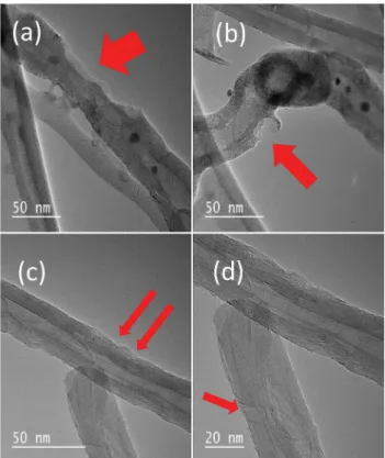
NH3 gas sensing resistance measurements were performed at room temperature and 2508C using a KSGAS6S gas sensing station (KENOSISTEC, Italy) that had a Keithley 6487 picoammeter/voltage source meter attached. A flow-through technique, with a constant flow rate of 250 mL min#1, was used to test the electrical and NH3gas sensing properties of the sensing films. A constant flux of synthetic air (0.5 L min#1) was used as a carrier gas into which the desired concentration of NH3gas was mixed. 3 Results and discussion Structural characterisa-tion of the MWCNTs was performed using HRTEM and SEM techniques. Figure 1(a–d) shows the TEM images of CNTs indicating defects on the walls of the CNTs of different shapes and sizes, which we believe play a significant role in the gas sensing mechanism. Furthermore,
from these HRTEM analyses, the average shell thickness was found to be approximately 7 nm, and the inner diameter approximately 15 nm. The SEM image in Fig. 2 shows the CNTs on an interdigitated substrate (see also the top left inset in Fig. 2) and a higher magnification image of the CNTs (see top right inset in Fig. 2) for one of the devices that
was used for the gas sensing and in situ Raman measure-ments. The top right inset in Fig. 2, shows a highly agglomerated sample and this is one of the major setbacks of CNT-based devices. This agglomeration makes it difficult to ensure 100% reproducibility, as all the devices tested had different resistances. However, in our setup we minimised this effect by using the same concentration of the CNT – solvent suspension and using two drops every time on each device. As such the devices had resistances with the same order of magnitude and gave the similar response (see Fig. 3; (a) calibration curves for two different samples and (b) calibration curves for four samples from the same batch). Dispersion of these materials in solvents like DMF helps to disentangle the tubes to produce more uniform devices. Despite this draw-back, the many entangled tubes ensure that a poor contact effect with the substrate for these devices was minimised.
The gas sensing responses of the MWCNTs to ammonia at 25 and 2508C for samples A1 and A2 are shown in Fig. 4 (a, i–iii). Samples A1 and A2 were taken from different batches but treated the same way to check reproducibility of the sample and device fabrication. Good reproducibility was observed as the results were comparable (see also Fig. 3(b) which shows the results of another three samples from batch A1). What is evident from this graph is that all devices have different resistance values (but with the same order of magnitude) as highlighted earlier. This is expected as it is
Figure 1 HRTEM images of MWCNTs showing defects of different shapes and sizes (a–d) shown by the red arrows.
Figure 3 (a) Calibration curves showing the variation of resistance with ammonia concentration for samples from different batches, (b) for samples from the same batch.
Figure 2 SEM image of one of the devices containing MWCNTs on the interdigitated substrate; upper-left inset shows the optical image of the substrate and upper-right shows a high-magnification image of MWCNTs.
currently impossible to ensure that every device has the same number of identical CNTs. The trends in resistance changes are similar showing that we achieved good reproducibility.
At 258C (Fig. 4(a) (i)), the sensor response is poor, and there is no clear transition in resistance as the gas concentration increases. We, however, notice a general increase in resistance at low NH3 concentrations below 40 ppm. We attribute this to the influence of oxygen in synthetic air used to dilute the ammonia gas. Synthetic air has about 23% oxygen and 77% nitrogen. At low ammonia concentrations, the influence of oxygen becomes significant. When the temperature was increased to 2508C, a clear drop in resistance was observed after the gas concentration exceeded 40 ppm (see red line in Fig. 4(a) ii and iii). The blue line in the graph shows the concentration of ammonia in ppm. The gas response improved after this transition, showing a faster recovery (ca. 80 s – recovery in resistance after NH3gas flow was stopped for each cycle) compared to that at 258C (ca. 130 s). The improved response and response rate is thus related to a thermally activated process. The first 40 ppm of NH3appears to play a significant role in the conductivity transition (see discussion below).
Due to the toxic nature of ammonia, levels of 40 ppm in the environment can be considered as high [23] and so this device based on MWCNTs gives an ammonia sensor for high concentration levels of ammonia such as found in
chemical manufacturing plants. However, with good calibration, low levels of ammonia can be detected. Figure 3, shows typical calibration curves of resistance vs ammonia concentration for the two MWCNT devices, A1 and A2. It can be seen from the calibration curves that the resistance decreased with ammonia concentration.
To obtain further information on the adsorption process, in situRaman studies were performed in four different steps, as outlined in the experimental section. The Raman spectra of MWCNTs are characterised by three well-known bands: a disorder induced D band at 1349 cm#1; a graphite G-band at ca. 1580 cm#1, which has a weakly asymmetric characteristic line shape and usually shows a pronounced splitting in individual tubes; and a second overtone of the D band at 2700 cm#1, which is known as the 2D band.
The results from the Raman measurements are shown in Fig. 4 (b and c). Little information was obtained from the intensity variation of the Raman spectra shown in Fig. 4 (b and c). The intensity is a measure of the phonon modes/molecular vibrations involved in the resonant Raman process [24]; hence, the intensity variations may differ solely because of differences in the amount of material at a particular spot on the device. However, other parameters such as the FWHM and intensity ratios (e.g. ID/IGor I2D/IG) can provide information about the intrinsic bonding, structural integrity or doping levels on the surface of the material.
The high frequency E2gRaman-allowed optical phonon (G) band at 1580 cm#1 and the two-phonon double resonance (2D) band at 2700 cm#1 are the most sensitive to silent defects such as intercalants, charge impurities and uni- or bi-axial strain [24]. On the other hand, the D band, which results from an A1g breathing mode at the Brillouin zone boundary, is activated by point defects and substitu-tional doping [25]. In this system (after device fabrication), the influence of point defects can be constant, and substitutional effects are unlikely to be noticed as the material recovers after the measurement process. The G and 2D bands carry much valuable information on the electron-phonon coupling (EPC), molecule intercalations and charge doping on the material surface [24].
The FWHM of the G band is known to be a measure of the structural disorder in carbon materials and when the G band position shifts to higher wavelengths the electron or hole doping is known to decrease [24]. Tight binding and density functional theory calculations have shown that EPC contributes significantly to the broadening of the G band [26]. This offers an alternative way to measure the EPC. From the Fermi golden rule, the EPC contribution to the FWHM of the G band is given by [24];
gEPC0 ¼ ffiffiffi 3 p a2 0 4M EPC G" 2# v2F ð1Þ
where M is the carbon mass, a0 is the graphite lattice
spacing, vF is the Fermi velocity and EPC G2
"
# represents the phonons around G in the K space. Taking a0¼ 2.46 Å,
Figure 4 (a) (i) Gas sensing response of MWCNT device A1 to ammonia gas at ca. 258C. (a) (ii and iii) Response to ammonia gas at 2508C of MWCNT devices A1 and A2; a clear transition in resistance is marked with a red line, (b) typical in situ Raman spectra of MWCNT device A1 measured at four steps in the experiment. (c) Typical in situ Raman spectra of MWCNT device A2 measured at four steps in the experiment.
vF¼ 8 " 105m s#1, and a Raman instrument resolution of
1.5 cm#1, we can estimate that the the EPC after gas exposure at some spots could decrease by about 20 (eV/Å)2 or rise by about 30 (eV/Å)2 during gas adsorption or recovery, respectively. The EPC determines the ultimate mobility of charge carriers; therefore, a decrease in the EPC improves the mobility, whereas an increase does the opposite. In this system, this behaviour translates to improved electrical conductivity during gas adsorption on defect sites.
The ratio I2D/IGcan be used to monitor the doping level because the G band always stiffens owing to doping effects (holes or electrons), whereas the 2D band responds differently to hole and electron doping; holes result in 2D phonon stiffening, and electrons have the opposite effect [24]. From the repeated Raman measurements on different samples, the average Raman data for each sample was fitted with five Gaussian peaks, as shown in Fig. 5 (a) [27]. The intensity ratios and FWHMs were then extracted and are shown in Fig. 5(b).
Figure 5(b# bottom graph) shows that the introduction of heat (stages 1–2) to the samples results in an increase in disorder (FWHM) probably due to increased lattice vibrations because of thermal energy effects. Comparison of stages 1 and 4 show that the samples do not fully recover in the 15 min time used during the Raman measurements. This effect is unlikely to be due to an irreversible process because the samples did recover fully after a longer recovery time.
From Fig. 5(b), it was observed that when the NH3gas was adsorbed on the material surface (stage 3), both the I2D/ IG and the FWHM of the G band intensity decreased. As mentioned earlier, a lower ratio means a higher electron doping level, which is also supported by a shift in the G band position to lower wavelengths by about 2–5 cm#1. From the
drop in the FWHM and using Eq. (1), the EPC aroundG was also shown to decrease. As mentioned earlier, the EPCs limit the ultimate mobility of carriers in the CNTs.
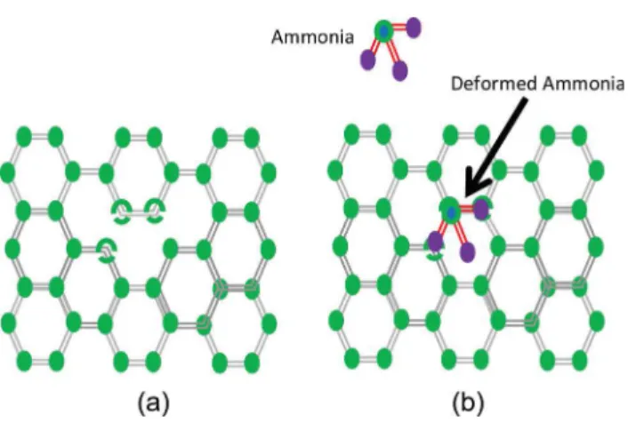
This result is initially surprising because the expecta-tion is that any foreign element attached to the surface should increase the disorder, and the opposite result would then be expected. However, if ammonia gas molecules are adsorbed on defect sites on the CNTs, this would suppress the second-order-defect associated Raman vibrations, resulting in a lower D band intensity. The adsorbed ammonia molecules appear to have a healing effect on the structural defects, which would explain why the FWHM also decreased when the gas was adsorbed on the surface. The schematic diagram in Fig. 6, illustrates one possible healing effect that could enhance the structural integrity of the CNT surface. This effect is favourable for small defects and at high temperatures probably because that is when the bond angles can easily be modified to accommodate foreign small molecules.
In stage 4, after the heating process was discontinued and the NH3 flow was stopped, the material started to recover, indicating that this effect is temporary and hence involves a reversible physisorption process. The observed changes in the intensity ratio and the FWHM values suggest that the gas response in Fig. 4(a) ii and iii, is due to ammonia gas molecules preferentially adsorbing on the defect sites of the MWCNTs. Attachment of the ammonia molecule via its lone pair of electrons would result in a drop in the resistance as the carrier density was increased. The improved gas response, after this temporary absorption, may be due to the better carrier mobility (as indicated by a decrease in the EPC) since the structural integrity of the material improved, as evidenced by the lower FWHM. The minimum amount of NH3required to occupy almost all the defect sites appears to be about 40 ppm, after which a significant drop in resistance is noted.
Figure 5 (a) Fitted Raman spectra from Fig. 4(b and c) for three of the experimental stages, (b) top graph shows the changes in the I2D/ IG ratio at the four stages of the experiment; the bottom graph shows the variation of the FWHM for the two samples. (lines used to guide the eye).
Figure 6 (a) Schematic view of a defective CNT wall (b) ammonia molecule being attached on the defect site and because of the large bond angles of the C–C– wall the ammonia molecule is strained.
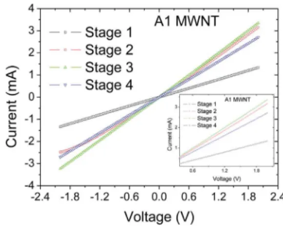
The improvement in carrier density is further supported by the results of current–voltage (I–V) characterisation studies. The data show an increase in conductivity when the ammonia gas molecules are adsorbed onto the surface of the MWCNTs. Figure 7 shows the I–V characterisation results for the CNTs during the four stages used in the experiment. An advantage of using many CNTs is that the I–Vresults show linear behaviour about the zero bias point, indicating near-perfect Ohmic contacts on the devices [21]. In stage 3, when the gas is passed over the sensor (with the heater on) the current flow increases by about 6% at a bias voltage of 1.8 V. This clearly indicates that the adsorbed gas molecules have improved the electrical properties of the material. The increase in conductivity between stages 1 and 2 is explained in terms of improved coupling between the electrodes and the CNTs. Changes between stage 3 and 4, are attributed to the desorption of the ammonia gas molecules from the CNT surface leading to a drop in conductivity.
An attempt was made to extend the studies to other gas molecules (NO/CO). However, no changes in conductivity were found for NO. A similar effect was observed for CO gas (see supplementary data), but the response was very weak. This would suggest that the MWCNTs are interacting with different gases in a selective manner and that NH3may be detected in the presence of these gases.
4 Conclusions In conclusion, defect sites on MWCNTs are proposed to be the preferred sites for interaction with gaseous ammonia molecules at 2508C. This thermally activated adsorption of NH3 gas molecules on such sites is seen to improve the electrical and gas response behaviour of the CNTs towards ammonia. A similar but smaller effect was observed for CO gas. This observation implies that gas molecule adsorption on CNTs may have a healing effect on the structural integrity of the material, which is enhanced at elevated substrate temperatures. This
work has provided some insight on the effect of temperature on ammonia adsorption on multiwalled carbon nanotubes, which might be used to tune selectivity.
Supporting Information Additional supporting information may be found in the online version of this article at the publisher’s web-site.
Acknowledgements GC, SSR and BM thank the De-partment of Science and Technology and the Council for Scientific and Industrial Research for a postdoctoral fellowship programme that funded this work under project number HQER27S. We also thank Dr Baban Dhonge for running the gas sensing experiments.
References
[1] K. Wetchakun, T. Samerjai, N. Tamaekong, C. Liewhiran, C. Siriwong, V. Kruefu, A. Wisitsoraat, A. Tuantranont, and S. Phanichphant, Sens. Actuators B 160, 580 (2011).
[2] R. Kumar, O. Al-Dossary, G. Kumar, and A. Umar, Nano-Micro Lett. 7, 97 (2015).
[3] S. Basu and P. K. Basu, J. Sens. 2009, 861968 (2009). [4] B. W. Mwakikunga, S. Motshekga, L. Sikhwivhilu, M.
Moodley, M. Scriba, G. Malgas, A Simo, B Sone, M. Maaza, and S. S. Ray, Sens. Actuators B: Chem. 184, 170–178 (2013).
[5] S. Some, Y. Xu, Y. Kim, Y. Yoon, H. Qin, A. Kulkarni, T. Kim, and H. Lee, Sci. Rep. 3, 1868 (2013).
[6] M. Sithiya, A. S. Prakash, K. Ramesha, J. M. Tarascon, and A. K. Shukla, J. Am. Chem. Soc. 133, 16291 (2011). [7] G. Chimowa, Z. P. Tshabalala, A. A. Akande, G. Bepete, B.
Mwakikunga, S. S. Ray, and E. M. Benecha, Sens. Actuators B: Chem. 247, 11–18 (2017).
[8] V. M. Aroutiounian, A. Z. Adamyan, E. A. Khachaturyan, Z. N. Adamyan, K. Hernadi, Z. Pallai, Z. Nemeth, L. Forro, A. Magrez, and E. Horvath. Sens. Actuators B 177, 308 (2013). [9] A. A. Khaleed, A. Bello, J. K. Dangbegnon, M. J. Madito, F. U. Ugbo, A. A. Akande, B. P. Dhonge, F. Barzegar, D. Y. Momodu, B. W. Mwakikunga, and N. Manyala, J. Mater. Sci. 52, 2035–2044 (2017).
[10] G. F. Ndlovu, W. D. Roos, Z. M. Wang, J. K. O. Asante, M. G. Mashapa, C. J. Jafta, B. W. Mwakikunga, and K. T. Hillie, Nanoscale Res. Lett. 7, 1–8 (2012).
[11] R. Taziwa, E. L. Meyer, E. Sideras-Haddad, R. M. Erasmus, E. Manikandan, and B. W. Mwakikunga, Int. J. Photoenergy 2012, Article ID 904323, 9 pages (2012).
[12] Y. Wang and J. T. W. Yeow, J. Sens. 493904 (2009). [13] J. Liu and G. Li, Sensors 13, 8814 (2013).
[14] O. K. Varghese, P. D. Kichambre, D. Gong, K. G. Ong, E. C. Dickey, and C. A. Grimes, Sens. Actuators B 81, 32 (2001). [15] M. S. Dresselhaus, G. Dresselhaus, R. Saito, and A. Jorio,
Phys. Rep. 409, 47 (2005).
[16] E. Llobet, Sens. Actuators B 179, 32 (2013).
[17] T. Zhang, S. Mubeen, N. V. Myung, and M. A. Deshusses, Nanotechnology 19, 332001 (2008).
[18] H. Chang and J. D. Lee, App. Phys. Lett. 79, 3863 (2001). [19] M. Boulova, A. Gaskov, and G. Lucazeau, Sens. Actuators B
81, 99 (2001).
[20] T. Pagnier, M. Boulova, A. Galerie, A. Gaskov, and G. Lucazeau, Sens. Actuators B 71, 134 (2000).
Figure 7 Current–voltage (I#V) characteristics of the MWCNT device A1 at four stages in the in situ experiments. The inset shows an expanded view of the same data showing the effect of the gas on the response.
[21] S. W. Gay and K. F. Knowlton, Virginia Cooperative Extension, publication 442, 110 (2005).
[22] B. W. Mwakikunga, M. Maaza, K. T. Hillie, C. J. Arendse, T. Malwela, and E. Sideras-Haddad, Vib. Spectrosc. 61, 105–111 (2012).
[23] A. C. Ferrari, Solid State Commun. 143, 47 (2007). [24] L. G. Cancado, A. Jorio, and E. H. M. Ferreira, Nano Lett. 11,
3190 (2011).
[25] A. C. Ferrari, J. C. Meyer, V. Scardaci, C. Casiraghi, M. Lazzeri, F. Mauri, S. Piscanec, D. Jiang, K. S. Novoselov, S. Roth, and A. K. Geim, Phys. Rev. Lett. 79, 187401 (2006). [26] M. Bradley, Multiplying Productivity: The Nicolet iZ10
module, Thermo Fisher Scientific, Madison, WI, USA. [27] Z. L. Wang, Nanowires and Nanobelts, Materials, Properties
and Devices, Metals and Semiconductor Nanowires (Springer, Atlanta, 2003), vol. 1, p. 57.