O
pen
A
rchive
T
OULOUSE
A
rchive
O
uverte (
OATAO
)
This is an author-deposited version published in :
http://oatao.univ-toulouse.fr/
Eprints ID : 19942
To link to this article : DOI:10.1109/ECMSM.2017.7945866
URL :
http://dx.doi.org/10.1109/ECMSM.2017.7945866
To cite this version : Jodin, Gurvan
and Scheller, Johannes
and
Rouchon, Jean-François
and Braza, Marianna
On the
multidisciplinary control and sensing of a smart hybrid morphing
wing. (2017) In: 2017 IEEE International Workshop of Electronics,
Control, Measurement, Signals and their application to Mechatronics
(ECMSM), 24 May 2017 - 26 May 2017 (Donostia-San Sebastian,
Spain).
Any correspondence concerning this service should be sent to the repository
administrator:
[email protected]
OATAO is an open access repository that collects the work of Toulouse researchers and
makes it freely available over the web where possible.
On the multidisciplinary control and sensing of a
smart hybrid morphing wing
Gurvan JODIN
∗, Johannes SCHELLER
†, Jean-Franc¸ois ROUCHON
‡, Marianna BRAZA
‡∗LAPLACE laboratory and IMFT institute, Toulouse, FRANCE
Email: [email protected]
†MIT and IMFT institutes, 77 Massachusetts Ave, Cambrigde, MA 02139, USA
Email: [email protected]
‡LAPLACE laboratory, 2 Rue Charles Camichel, BP 7122, F-31071 Toulouse, FRANCE
Email: [email protected]
§IMFT institute, 1 All´ee du professeur Camille Soula, 31400 Toulouse, FRANCE
Email: [email protected]
Abstract—Morphing wing technology is of great interest for improving the aerodynamic performance of future aircraft. A morphing wing prototype using both surface embedded Shape Memory Alloys (SMA) and piezoelectric macro fiber composite (MFC) actuators has been designed for wind tunnel experiments. This smart wing is a mechatronic system that contains embed-ded sensors to measure the surrounding flow and control the actuators. This article will focus on the control of the cambering system which is achieved using a group of nested control loops as well as on the perspective of a novel control strategy using in-situ temperature measurements. It will be shown that by exploiting the inherent hysteretic properties of the SMAs cam-bering a significant reduction in power consumption is possible by appropriately tailoring the control strategy. Furthermore, by comparing the post-processed pressure signals recorded during the wind tunnel experiments to the aerodynamic performance gains a perspective for a novel in-situ control will be shown.
I. INTRODUCTION
Nowadays the environmental compatibility of aircraft is an important issue. This leads to the design of more efficient aircraft. With respect to aerodynamic performance, current planes have their wings optimized for one cruise flight step. During flight, the altitude, the weight and the speed are changing so one fixed wing shape is sub-optimal. It has been shown that changing the shape of the wing can save several percents of fuel burn for a regional passenger aircraft [1]. The concept of real time wing shape adaptation is called morphing. While the benefits of morphing wings are known, the ways to obtain these benefits are a subject of intense research. Actuation system weigh, safety and reliability are examples of common issues. Some research focuses on relatively high Technology Readiness Level (TRL) targeting current indus-trial airliners at true scale. The European research project SARISTU [2] and the Adaptive Compliant Trailing Edge Flap [3] concept from the USA both address morphing wings for industrial airliners. Flight tests are currently in progress, demonstrating the effectiveness and airworthiness of the so-lutions. However, these new adaptive structures are actuated through conventional actuators like servomotors.
Recent advances in the field of smart materials show the potential to overcome difficulties to make a wing both stiff
enough to withstand the loads and flexible enough to be easily deformed [4]. As complex multidisciplinary approaches are needed, such technologies are primarily limited to laboratories, with low TRL. Considering electroactive materials, Shape Memory Alloys (SMAs) and piezoelectric materials are com-monly used. SMAs are characterized by thermomechanical behaviors, and most of applications use Joule heating to activate the SMAs. Diverse morphing concepts have been developed [5]. Typical applications are shape adaptation at low deformation speed. Some SMAs are able to carry more than 400 MPa and can recover strain of over 4%. Research shows the ability of SMAs to reach one million actuation cycles [6]. Piezoelectric materials’ electromechanical behavior is activated via the electric field [4]. The most used mate-rial is lead zirconate titanate (PZT). The developments of piezoelectric composites allows for a simple implementation; piezoelectric composite patches glued on the structure are often used as bending actuators that control the shape of a wing. Despite the brittle nature of the PZT ceramics they provide high frequency actuation with an excellent life cycle. The previously cited work generally achieves the desired functions using one specific smart material. A combination of both SMAs and PZT can enhance the global performance. The synergistic smart morphing aileron [7] is the combination of a SMA actuated hinge followed by a flexible piezoelectric driven trailing edge.
The French laboratories LAPLACE and IMFT have been focused on studying electroactive morphing for more than ten years in various collaborative research projects. A SMA actuated plate [8] and a NACA0012 wing with a vibrating trailing edge [9] are the precursors of a NACA4412 hybrid morphing wing [10]. This prototype both embeds SMAs and trailing edge piezoelectric fiber actuators [11]. This allowed both large deformations (∼10% of the chord) at limited frequency (≤ 1 Hz) and small deformations (several mm) at higher frequencies (≤ 100 Hz). It has been shown that the trailing edge vibration interacts with the shear layer. The wing’s wake energy has been reduced, leading to an improvement in aerodynamic performance [10].
pressure sensors
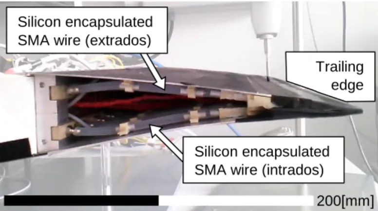
Fig. 1. Picture of the hybrid wing model on its stand out of wind tunnel.
To the authors’ knowledge, the originality of the present work is the study of the links between camber control, vibrating trailing edge and the airflow dynamics. Previous work has primarily targeted the Micro Air Vehicle (MAV) scale; now the purpose of the present work is the up-scaling towards commercial passenger airliners. In cooperation with Airbus, a first step is a reduced scale wing with an innovative electroactive hybrid morphing flap design. This paper firstly introduces the wing prototype. Secondly, a focus on the link between control law, power consumption and actuator design is provided. Thirdly, wind tunnel experimental results are presented; showing some answers on the use of embedded sensors to estimate morphing performances.
II. ELECTROACTIVE HYBRID MORPHING WING PROTOTYPE
A. Hybrid morphing
The airflow around a wing can be decomposed in two space-time domains: a global space-time averaged effect - influenced by large wing shape deformation at low frequencies - and small amplitude higher frequency dynamics - influenced by small amplitude but higher frequency actuation. These two different effects justify the use of two actuators based on two different electroactive materials. The here presented morphing wing embeds both camber control and Higher Frequency Vibrating Trailing Edge (HFVTE) actuators. Fig. 1 presents the hybrid morphing prototype. The chord length is 700 mm, the span is 590 mm.
B. Higher Frequency Vibrating Trailing Edge actuator The HFVTE actuation system is based on piezoelectric Macro Fiber Composite (MFC) patches which expand in length when subject to an electric field. Piezoelectric patches are glued on both sides of a metallic substrates. By alternat-ingly applying a voltage to the patches, the patches generate a bending moment which results in actuator vibration. To respect the shape of the airfoil, the HFVTE actuators are placed at the trailing edge, covered by a specifically designed silicone shell. As presented in Fig. 2, vibrations of 0.7 mm can be reached at frequencies up to 100 Hz. (See [12] and [13] for more details on the design.)
C. Camber control actuator
The camber actuation system is designed to bend the trailing edge structure while withstanding aerodynamic loads. The
ac-0 100 200 300 400 0 0.1 0.2 0.3 0.4 Actuation frequency Fa (Hz) Amplitude A (mm) 1/1000 chord 0.5/1000 chord
Fig. 2. Measured amplitude displacement A of the trailing edge, depending on the actuation frequency Fa. This frequency response measurement of the
actuator has been performed with 1 kV applied voltage on the MFC patches, using a high-speed camera.
tuator is based on surface embedded SMAs. Three SMA wires are embedded under the upper skin and three other SMA wires are embedded on the lower skin, as shown in Fig. 3. SMAs are characterized by a strongly non-linear thermomechanical coupling, which has been modeled and understood during the last decades [14]. The actuator has been modeled in [12] and [13]; to sum up the principle, cold SMA are pseudo-plastic and can be easily stretched thanks to a low stress plateau. The SMAs are heated through Joule heating generating strong forces to recover their initial shapes. To easily design the mock-up and as cold SMA are very flexible, the SMA stiffness is neglected. This creates a sub-optimal design with a large amount of SMA, but the design solution is reliable and stiff regarding to aerodynamic loads. The maximum trailing edge deflection is about -25 mm to +20 mm. This corresponds to a controllable camber modification range of 22% (from -10% to +12%) of the actuated chord.
III. CAMBER CONTROL:CONTROL LOOP AND PERFORMANCES
To precisely reach the desired deformations while control-ling 6 independent SMA wires, temperature and deformation sensors are implemented. One thermocouple per SMA wire
Trailing edge
Silicon encapsulated SMA wire (intrados) Silicon encapsulated
SMA wire (extrados)
200[mm]
−25 −20 −15 −10 −5 0 5 10 15 20 −25 −20 −15 −10 −5 0 5 10 15 20
True measured displacement (mm)
Reconstructed displacement
(mm)
Ideal response
Reconstructed displacement
Fig. 4. Characterization of the reconstructed displacement evaluated from embedded strain gauges.
is used. One strain gauge bridge is implemented per up and down SMA pair, to reconstruct the trailing edge displacement. Two strain gauges are glued on the upper skin and the other two are on the lower skin. This atypical gauges distribution has been calibrated using an external displacement sensor that measured the trailing edge displacement. A polynomial interpolation ensures an accurate trailing edge displacement reconstruction from the bridge’s signal. As shown in Fig. 4, the average absolute error is under 0.4 mm for trailing edge displacements up to 10 mm. Over 10 mm, hysteresis decreases the accuracy to 1 mm.
These sensors are used in two nested closed loops to control the camber. The reconstruct displacement is compared to a camber reference. Then a Proportional Integral (PI) controller send a SMA temperature reference to the temperature con-trollers. These controllers use temperature sensor information to provide heating and cooling commands via PI controllers. The control architecture is summed up in Fig. 5. Tempera-ture references are output from displacement controller, with limited slope, in order to ensure a uniform variation of every SMA actuator. The displacement controller has a custom anti-windup on the PI’s integrator in order to avoid over integration during the temperature slopes.
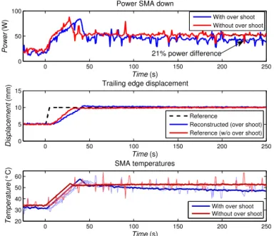
The performance of the nested-loop control is visible Fig. 6 for two displacement controller settings. A displacement step is applied on the controller. Rising the trailing edge displace-ment from 5 mm to 10 mm needs an increase of heating power to rise SMA temperature. The control strategy with displacement overshoot seems to be more efficient in steady
Current driver/ Air valve SMA structure Temperature controller
T°
ctrl Dispctrl Displacement controller Temperature sensor Displacementsensor and reconstruction
Camber Camber
ref.
Fig. 5. Nested control loop architecture of the camber control actuator.
0 50 100 150 200 250
0 50 100
Power SMA down
Time (s)
Power
(W)
With over shoot Without over shoot
0 50 100 150 200 250
0 5 10 15
Trailing edge displacement
Time (s)
Displacement
(mm)
Reference
Reconstructed (over shoot) Reference (w/o over shoot)
0 50 100 150 200 250 20 30 40 50 60 Time (s) Temperature (°C) SMA temperatures
With over shoot Without over shoot
21% power difference
Fig. 6. Control strategy influence of the camber control actuator. From top to bottom: instantaneous SMA power consumption, reconstructed displacement, SMA temperatures.
power consumption than the strategy without overshoot. Over-shoots in displacement lead the controller to decrease the final SMA temperature reaching the reference displacement. The overshoot effect is often seen as a control drawback; but due to the SMA activation temperature hysteresis, the final required temperature to obtain trailing edge position when decreasing the displacement is lower than the temperature needed to obtain the same position when increasing the displacement. This effect is clearly visible on Fig. 7, where temperatures are drawn depending on displacement for the same experiment as presented in Fig. 6. The required SMA temperature difference between the two strategies is over 6◦C. Finally, a simple change in the control strategy leads to a reduction of more than 20% of required heating power to maintain the displacement.
4 5 6 7 8 9 10 11 30 35 40 45 50 55 60 Temperature (°C) Displacement (mm)
With over shoot Without over shoot Final with over shoot Final without over shoot
Fig. 7. Control strategy influence of the camber control actuator. Temperature - displacement plane representation of the experiments.
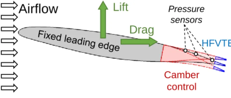
Camber control HFVTE Pressure sensors
Airflow
Lift
Drag
Fig. 8. Scheme of the wind tunnel experiment.
IV. WIND TUNNEL EXPERIMENTS
A. Experimental set-up
The wing model is tested in a subsonic wind tunnel. The test section is 592 mm width per 712 mm high. The wing chord c is 700 mm as previously mentioned. The wing is mounted at a maximal incidence of 10◦. As a result a blockage ratio of 18% is obtained. The blockage ratio effects are found to be acceptable in the present experiments which focus on the morphing effects. This is done by comparing a morphing configuration to the non-actuated case, both of which are subject to the same blockage ratio. The turbulence intensity of the inlet section is about 0.1% of the free stream velocity. Measurements are performed at ambient temperature (22◦C). Fig. 8 presents the experimental wind tunnel set up. An aerodynamic balance based on strain gauges has been designed to measure lift and drag force on the wing. Precautions in design and mounting have been taken to ensure the quality of the measures despite the vibrations and the wires coming from the embedded sensors and actuators. Three dynamic pressure transducers (MEGGIT 8507C-1) are implemented on the suc-tion surface (upper skin) of the prototype. They are lined up one behind the other. The respective locations of the sensor P1, P2 and P3 are closed to the trailing edge, i.e. respectively at 80%, 86% and 93% of the wing chord. An experimental campaign exploring the influence of free stream velocity, angle of attack, camber, HFVTE frequency and HFVTE amplitude is performed. Illustrations of the amplitude of deformations are given in Fig. 8. For every experimental morphing experiment, forces, pressures, wind conditions and actuator information are recorded for 20 s. This record time has been found long enough to ensure a good statistical convergence.
B. Morphing effects
1) Hybrid morphing – Camber and HFVTE coupled effects: To investigate the impact of all variables, thousands of runs are performed. Fig. 9 presents the results of 476 experiments, at incidence of 10◦and Reynolds number Re = 106(Re = U∞·c
ν
where U∞ is the free stream velocity – 21.5m/s here – and
ν is the kinematic viscosity). Lift coefficients are computed from time averaged aerodynamic force data on acquisitions for camber control that displace the trailing edge from -10 to +10 mm (i.e. +/ − 1.5%c) and trailing edge vibrations at frequencies from Fa= 0 − 250Hz (i.e. fa∗ =0 to 8.3), where
Fa is the HFVTE actuation frequency and the dimensionless
actuation frequency fa is defined by fa =FUa∞·c. The lift
coef-ficient surface is plotted as a function of camber and vibration frequency. Each experiment testing a HFVTE configuration is preceded by a reference measure with the same camber, the same velocity and the same incidence, but with no trailing edge vibration. This ensures the accuracy in capturing the higher frequency-low amplitude actuation effects. At a given camber, the additional modifications due to the HFVTE are represented by vertical bars. The colors of these bars indicate if the HFVTE actuation increases the lift (green bars) or decreases the lift (red bars) compared to the experiment at same camber without HFVTE actuation.
The first noticeable result is the well known effect of the camber on the lift. Positively increasing the camber raises the lift. Notice on one hand that up and down deformed shapes are different, leading to non-symmetrical lift effects for negative and positive cambers respectively. On the other hand, characterizing the effects of trailing edge vibrations is less evident. In fact, according to Fig. 9, a frequency range from 100 Hz to 250 Hz (fa∗∈ [3.3 · · · 8.3]) seems to be beneficial for
the lift, especially for large cambers. On the other side, at low cambers the effect of the vibration on the lift is reduced and the frequency range is shifted. The strong coupling between the camber and the vibrating trailing edge is complex. As the effects of camber have already been largely assessed (see for instance Ref. [15]), the following section focuses on the effect of the vibrating trailing edge on the baseline cambered airfoil. 2) HFVTE effects at initial cambered airfoil: Dedicated experiments focus on the influence of the trailing edge vi-brations on the flow, at fixed camber. For instance, Fig. 10 presents the processed data from 500 experiments, each during 20 s. HFVTE frequency range is 12 Hz to 450 Hz (i.e. fa∗ ∈ [0.8 · · · 30]); 5 amplitude levels are tested from 20% to 100% of the maximum amplitude of the actuators ; Reynolds number here is Re = 105. Particular attention has been payed to repeatability and accuracy of the measures. The order of the measures has been generated randomly, in order to prevent any memory or hysteresis effect from the sensors. Finally, one measure at a given HFVTE setting is compared to a previous and a following reference measure with no actuation.
Fig. 10 shows the variation of the lift coefficient in relation with the actuation frequency. The different actuation amplitude are drawn in different colors. Pale areas described the varia-tions of the measures between the two experiments whereas the darker lines are the average values. The experiments are re-peatable with +/ − 0.14% lift difference. The first observation is the effect of the amplitude. Generally, the larger the HFVTE amplitude the larger the gain. This clearly indicates that if the actuator could vibrates at larger amplitudes, more gains can be achieved. But increasing amplitude over a certain limit would decreases the gains, as reported in [16] for the forced active control of airflows. Secondly, a frequency threshold appears close to 100 Hz, separating low HFVTE effects area from higher gain area. This threshold is linked to the first resonance of the HFVTE actuator which can be seen by the 110 Hz
0 1 2 3 4 5 6 7 8 22 24 26 28 ∆ Cl /C l0 (% ) +1.5%C camber 0 1 2 3 4 5 6 7 8 −2 0 2 4 ∆ Cl /C l0 (% ) Initial camber 0 1 2 3 4 5 6 7 8 −9 −8 −7 −6 −5 −4 ∆ Cl /C l0 (% ) HFVTE frequency f∗ a −1.5%C camber
Fig. 9. Modification of the measured lift coefficient Clas a function of the dimensionless camber and the dimensionless actuation frequency. The percentage
lift modification is normalized to the measured lift coefficient without any morphing Cl0. Corresponding 2D plots of three selected cambers are presented
on the right. The blue areas around the data correspond to the 95% confidence level. Camber range is −10 to +10mm and frequency range is 0 − 250Hz. Reynolds number for this experiment is Re = 106.
peak in Fig. 2. Complex structural vibrations are detected with accelerometer on the wing, but the understanding of the coupling between wing structural resonance modes and the effects on flow is the purpose of next work.
Finally, it is worth noting that for the two tested velocity – i.e. the two Reynolds numbers Re = 106 or 5 · 105 – experimental gains above 2% have been identified, thanks to small vibrations of the trailing edge.
C. Morphing and sensing
Experimental morphing performance enhancements are characterized using an aerodynamic balance. This instrumental device cannot easily be embedded on aircraft. Other embedded sensors are needed. The three dynamic pressure sensors P1, P2 and P3 are used to this purpose.
The recorded pressure signals are useful. For instance they contain vortex signature in their frequency spectra that could be analyzed. A simpler analyze that can be used as morphing
Fig. 10. Impact of the HFVTE frequency and amplitude on the lift coefficient Cl. Reynolds number for this experiment is Re = 5 · 105.
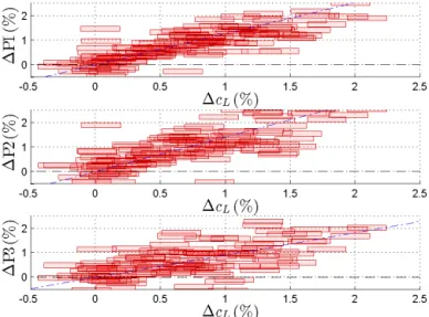
efficiency estimator is the evolution of time average pressures presented in Fig. 11. Indeed, an increase of the absolute value of the pressure increases the lift; as the lift is the vertical component of the resulting pressure forces. Notice that the measured pressures are strongly affected by the propagated vibrations in the structure, as the sensors are embedded into the structure. So the signal variance is more affected by the vibrations than the pressure variations. Nevertheless, the time average pressures of the three sensors in Fig. 11 are correlated to the lift gain. Then these sensors demonstrate the suitability for the detection of aerodynamic performance enhancement thanks to HFVTE actuation. Next work has to focus on the
Fig. 11. Lift coefficient evolution against time average pressure variations of the 3 transducers P1 to P3. The plotted data corresponds to all HFVTE actuated experiment at Re = 5 · 105 at initial camber.
signal processing to determine an accurate observer of the aerodynamic gains.
V. CONCLUSION
This article presented the multidisciplinary coupling be-tween an innovative mechatronic hybrid morphing wing proto-type and the aerodynamic forces. The different time scales of aerodynamic phenomena justify the use of two electroactive smart material based actuators. Integration of piezoelectric and shape memory alloy actuators in the prototype requires a multidisciplinary design approach to fulfill the design target during the construction and to achieve accurate control of the innovative prototype, before moving towards the dedicated wind tunnel experiments. It has been shown that the control law of the SMAs can decrease the steady power consumption by more than 21%. Also, the aerodynamic performance en-hancements are closely linked to the coupled actuator-structure dynamic behavior.
The camber modifications is able to change the lift by 23% and the drag by 35%, leading a lift over drag ratio enhance-ment of 16%. Additionally the actuated small vibrations of the trailing edge can increase the performances by 2% in addition to the camber gains. Embedded pressure sensors show the ability to estimate the morphing gains without needing external sensors.
The next step focuses on both the sensors and actuators. A better understanding of the fluid mechanism is needed to estimate in real time the gains with embedded sensors. A full scale flap demonstrator equipped with hybrid morphing actuator is currently under construction.
REFERENCES
[1] Z. Lyu and J. R. R. A. Martins, “Aerodynamic shape optimization of an adaptive morphing trailing edge wing,” Journal of Aircraft, vol. 52, p. 1951–1970, November 2015.
[2] I. Dimino, M. Ciminello, A. Concilio, R. Pecora, F. Amoroso, M. Magnifico, M. Schueller, A. Gratias, A. Volovick, and L. Zivan, Smart Intelligent Aircraft Structures (SARISTU): Proceedings of the Final Project Conference. Cham: Springer International Publishing, 2016, ch. Distributed Actuation and Control of a Morphing Wing Trailing Edge, pp. 171–186. [Online]. Available: http://dx.doi.org//10. 1007//978-3-319-22413-8 9
[3] S. Kota, P. Flick, and F. Collier, “Flight testing of the flexfloil tm adaptive compliant trailing edge,” in 54th AIAA Aerospace Sciences Meeting, 2016, p. 0036.
[4] S. Barbarino, O. Bilgen, R. M. Ajaj, M. I. Friswell, and D. J. Inman, “A review of morphing aircraft,” Journal of Intelligent Material Systems and Structures, vol. 22, no. 9, pp. 823–877, 2011.
[5] S. Barbarino, E. I. S. Flores, R. M. Ajaj, I. Dayyani, and M. I. Friswell, “A review on shape memory alloys with applications to morphing aircraft,” Smart Materials and Structures, vol. 23, no. 6, p. 063001, 2014. [Online]. Available: http://stacks.iop.org/0964-1726/23/i=6/a=063001 [6] J. M. Jani, M. Leary, A. Subic, and M. A. Gibson, “A review of shape
memory alloy research, applications and opportunities,” Materials & Design, vol. 56, pp. 1078–1113, 2014.
[7] A. M. Pankonien, C. T. Faria, and D. J. Inman, “Synergistic smart mor-phing aileron: Experimental quasi-static performance characterization,” Journal of Intelligent Material Systems and Structures, vol. 26, no. 10, pp. 1179–1190, 2015.
[8] M. Chinaud, J. Rouchon, E. Duhayon, J. Scheller, S. Cazin, M. Marchal, and M. Braza, “Trailing-edge dynamics and morphing of a deformable flat plate at high reynolds number by time-resolved {PIV},” Journal of Fluids and Structures, vol. 47, pp. 41 – 54, 2014, special Issue on Unsteady Separation in Fluid-Structure Interaction-l. [Online]. Available: http://www.sciencedirect.com/science/article/pii/ S0889974614000231
[9] J. Scheller, M. Chinaud, J. Rouchon, E. Duhayon, S. Cazin, M. Marchal, and M. Braza, “Trailing-edge dynamics of a morphing {NACA0012} aileron at high reynolds number by high-speed {PIV},” Journal of Fluids and Structures, vol. 55, pp. 42 – 51, 2015. [Online]. Available: http://www.sciencedirect.com/science/article/pii/S0889974615000158 [10] J. Scheller, K. J. Rizzo, G. Jodin, E. Duhayon, J. F. Rouchon, and
M. Braza, “A hybrid morphing naca4412 airfoil concept,” in Industrial Technology (ICIT), 2015 IEEE International Conference on, March 2015, pp. 1974–1978.
[11] J. Scheller, G. Jodin, K.-J. Rizzo, E. Duhayon, J.-F. Rouchon, M. Tri-antafyllou, and M. Braza, “A combined smart-materials approach for next-generation airfoils.” Solid State Phenomena, vol. 251, 2016. [12] Jodin, Gurvan and Scheller, Johannes and Rizzo, Karl-Joseph and
Duhayon, Eric and Rouchon, Jean-Francois and Braza Marianna, “Dimensionnement d’une maquette pour l’investigation du morphing ´electroactif hybride en soufflerie subsonique,” in Congr`es Franc¸ais de M´ecanique, Online AFM, Association Franc¸aise de M´ecanique, 2015, 2015.
[13] G. Jodin, J. Scheller, E. Duhayon, J.-F. Rouchon, M. Triantafylllou, and M. Braza, “Implementation of a hybrid electro-active actuated morphing wing in wind tunnel,” {To appear in} Solid State Phenomena, 2017. [14] C. Lexcellent, Shape-memory alloys handbook. John Wiley & Sons,
2013.
[15] I. Abbott and A. von Doenhoff, Theory of Wing sections. New York, NY: Dover Publication, Inc., 1949.
[16] S. S. Collis, R. D. Joslin, A. Seifert, and V. Theofilis, “Issues in active flow control: theory, control, simulation, and experiment,” Progress in Aerospace Sciences, vol. 40, no. 4, pp. 237–289, 2004.