Science Arts & Métiers (SAM)
is an open access repository that collects the work of Arts et Métiers Institute of Technology researchers and makes it freely available over the web where possible.
This is an author-deposited version published in: https://sam.ensam.eu Handle ID: .http://hdl.handle.net/10985/19569
To cite this version :
M. LI, Adil BENAARBIA, A. MORRIS, W. SUN - Assessment of potential service-life performance for MarBN steel power plant header under flexible thermomechanical operations - International Journal of Fatigue - Vol. 135, p.105565 - 2020
Highlights:
Strain-controlled LCF and CFI tests of MarBN are conducted over a range of temperatures.
The cyclic softening increases and fatigue life reduces due to the additional strain dwell periods.
A unified viscoplastic model is implemented into Abaqus code to capture the deformation mechanisms of a fossil-fired superheater header.
SWT approach is adopted to assess the service-life performance of MarBN component for future USC application.
1 2 3 4 5 6 7 8 9 10 11 12 13 14 15 16 17 18 19 20 21 22 23 24 25 26 27 28 29 30 31 32 33 34 35 36 37 38 39 40 41 42 43 44 45 46 47 48 49 50 51 52 53 54 55 56 57 58 59 60 61 Nomenclature strain-range strain-rate
total strain tensor
elastic strain tensor
viscoplastic strain tensor
viscoplastic strain-rate tensor
maximum principal strain-range
viscoplastic multiplier
viscoplastic multiplier rate
stress tensor
stress rate tensor
deviatoric stress tensor viscous stress
maximum principal stress
E Young's modulus
fourth-order elastic stiffness tensor
non-linear kinematic stress
isotropic hardening stress
drag stress
von-Mises yield function
power-law function
the second invariant
k cyclic yield stress
viscoplastic resistance
viscoplastic exponent
linear hardening term dynamic recovery term
, temperature-rate term
, kinematic hardening parameters
, isotropic hardening parameters
fatigue strength
fatigue strength exponent
fatigue ductility coefficient
fatigue ductility exponent
Nf number of cycles to failure
*Manuscript (clean and updated version)
1 2 3 4 5 6 7 8 9 10 11 12 13 14 15 16 17 18 19 20 21 22 23 24 25 26 27 28 29 30 31 32 33 34 35 36 37 38 39 40 41 42 43 44 45 46 47 48 49 50 51 52 53 54 55 56 57 58 59 60 61 T absolute temperature
1 2 3 4 5 6 7 8 9 10 11 12 13 14 15 16 17 18 19 20 21 22 23 24 25 26 27 28 29 30 31 32 33 34 35 36 37 38 39 40 41 42 43 44 45 46 47 48 49 50 51 52 53 54 55 56 57 58 59 60 61
Assessment of potential service-life performance for MarBN steel power plant header under flexible thermomechanical operations
Ming Lia*, Adil Benaarbiab, Andy Morrisc, Wei Suna
a Department of Mechanical, Materials and Manufacturing Engineering, University of Nottingham,
Nottingham, Nottinghamshire NG7 2RD, UK
b Arts et Métiers, CNRS, Université de Lorraine, LEM3, F-57000 Metz, France
c EDF Energy, West Burton Power Station, Retford, Nottinghamshire DN22 9BL, UK
Abstract: This paper is concerned with the service-life assessment of 9Cr steels superheater outlet steam header subjected to realistic subcritical and future ultra-super critical flexible operating conditions. The proposed methodology is achieved via a combined program of high temperature strain-controlled fatigue tests, temperature- and time-dependent unified viscoplastic model for thermomechanical fatigue analysis, and Smith-Watson-Topper critical plane criterion for multi-axial life prediction. Samples of idealised operational transients with particular attention on the starting-up cycle is fully coupled with the computational modelling of header component for the high temperature performance assessment. The predicted results indicate that: (i) the header shell inner-bore saddles at weld regions are the critical locations that lead to earlier potential fatigue crack initiation, and (ii) the predicted lifetime under subcritical conditions correlates reasonably with the industrial experience. A steam header manufactured from MarBN operating under ultra-super critical condition is shown to have comparable life performance with the P91 header operating under subcritical condition.
Keywords: MarBN steel, thermomechanical fatigue, unified viscoplasticity, superheater header, service-life assessment.
1 2 3 4 5 6 7 8 9 10 11 12 13 14 15 16 17 18 19 20 21 22 23 24 25 26 27 28 29 30 31 32 33 34 35 36 37 38 39 40 41 42 43 44 45 46 47 48 49 50 51 52 53 54 55 56 57 58 59 60 61 1. Introduction
The most important challenges facing next generation power plants include improving efficiency and reducing CO2 emissions, whilst maintaining safe and reliable operation. Accordingly, additional flexible conditions are needed in the power plant to accommodate rapid load variation of fossil-fired power plants, which will cause lifetime reduction of component due to alternating stresses during transient processes [1, 2]. The thermodynamic efficiency of fossil-fired power plants can be improved by increasing the pressure and boiler outlet temperature, i.e. operating above 600°C is termed as ultra-super critical (USC) [3]. Fig. 1 illustrates the average starts per year on a 500MW unit (mainly flexible operation) during the last 21 years in a fossil-fired power plant in the UK [4]. Key issues however still exist, in relation to life prediction to guide the scope of periodic outage inspections of critical high temperature components (typically fabricated from a range of ferritic steels and 9Cr steels, such as P91). From a material perspective the challenges also include: (i) extrapolation to more realistic plant operations resulting in creep-fatigue interaction (CFI) deformation, and (ii) thermomechanical fatigue (TMF) due to the combination of flexible operation and complex thick-wall component geometries [5-9].
MarBN (MARtensitic 9Cr steel strengthened by Boron and Nitrides) has been identified as a candidate material, originally designed for increased temperature operation of thick section boiler components for next generation USC applications above 600°C. It has been reported in [10] that the boron and nitrogen stabilise the lath martensitic microstructure and reduce the rate of Ostwald ripening for M23C6 carbides near prior austenite grain boundaries (PAGBs) for improved the mechanical strength compared with the existing 9Cr steels in short-term creep, high temperature low cycle fatigue (LCF) and CFI [11-16], for example, Barrett et al. [11] and O'Hara et al. [15, 16] experimentally reported that the MarBN steel exhibited an increased stress-range of approximately 20% compared with the P91 steel. LCF and CFI tests
1 2 3 4 5 6 7 8 9 10 11 12 13 14 15 16 17 18 19 20 21 22 23 24 25 26 27 28 29 30 31 32 33 34 35 36 37 38 39 40 41 42 43 44 45 46 47 48 49 50 51 52 53 54 55 56 57 58 59 60 61
on MarBN under high temperature were recently conducted by Benaarbia et al. [13] and O'Hara et al. [15, 16], which indicates that the additional short-term creep is detrimental to the fatigue life and cyclic strength. Additionally, different kinds of fatigue tests with varied hold periods were carried out in [13] indicating the effects of applied loadings on the resultant microstructural evolution of MarBN at high temperature. Besides the work mentioned above, the authors are not aware of any other published experimental work on MarBN under high temperature LCF and CFI with the purpose to explore the possible future USC application by comparing with existing 9Cr steels.
High temperature and pressure components manufactured from P91 steel have received a lot of attention to accommodate experimental data in computational models, in order to investigate the consequent deformation behaviors. However, only few studies have been carried out to assess the lifetime of such component under flexible operation. Work carried out in [7-9, 17-19] has reported that the steam headers are more susceptible to CFI and TMF due to flexible operation, leading to microstructural degradation and reduction in component life. Rouse et al. [20] proposed a Chaboche type based model, considering the effect of variable steam flow conditions within the header component on the stress-strain evolution at the localized region. Finite element (FE) analyses have been performed in [21] to study the effect of different thermal cycles on fatigue life of steam headers without explicitly considering the viscous effect of power plant material for the operation at stabilized maximum internal loads. T. Hassan et al. [22] employed a unified viscoplasticity model based on continuum damage mechanics (CDM) to evaluate the CFI damage behaviour and predict service-life of a header component. The two-layer viscoplasticity model of Farragher et al. [5] was adopted within the FE code for TMF analysis of a P91 header and the service-life were predicted through a critical-plane approach, although the material models adopted in [5, 22] were not calibrated with CFI experimental data of the candidate material under
1 2 3 4 5 6 7 8 9 10 11 12 13 14 15 16 17 18 19 20 21 22 23 24 25 26 27 28 29 30 31 32 33 34 35 36 37 38 39 40 41 42 43 44 45 46 47 48 49 50 51 52 53 54 55 56 57 58 59 60 61
anisothermal conditions. In summary, the previous studies mainly focus on the analysis of mechanical deformation of header component by neglecting the idealised loading histories of flexible operation and viscous effect of the candidate material at varied temperatures, however, the lifetime assessment during flexible transient processes coupled with unified thermodynamic viscoplastic material law was scarce. Therefore, in order to realise the potential performance of MarBN for the future USC power plant application, a unified viscoplasticity framework, which represents both the viscoplastic responses and temperature-dependent material behaviors under flexible thermomechanical operation for lifetime assessment is required.
The first part of this paper introduces the MarBN steel, LCF and CFI experimental results, followed by an anisothermal temperature- and time-dependent viscoplasticity material modelling framework including the material parameter identification and calibration. The methodology for the service-life prediction of a superheater steam header based on high temperature viscoplastic analyses is then presented. One of the key objectives of the current work is to incorporate the uniaxial experimental fatigue data of the material under investigation with representative flexible operation data in a numerical model to explore the possible future service-life performance of MarBN at the component level. The findings covering failure locations and life estimation are provided with a comparison between current P91 steels in-service at subcritical steam condition and MarBN for possible future USC applications.
2. Material and experimental program 2.1. Material
MarBN steel exhibits a hierarchical arrangement, comprising of prior austenite grains (PAGs), packets, blocks, and laths. The PAGs can be further sub-divided into packets with
1 2 3 4 5 6 7 8 9 10 11 12 13 14 15 16 17 18 19 20 21 22 23 24 25 26 27 28 29 30 31 32 33 34 35 36 37 38 39 40 41 42 43 44 45 46 47 48 49 50 51 52 53 54 55 56 57 58 59 60 61
block including lath distributions with low angle boundaries [12, 23, 24]. The chemical composition of the investigated tempered MarBN steel is given in Table 1. The test specimens were extracted from forged bars which were obtained after normalizing tempering at 1200oC for 4h followed by a tempering treatment at 765oC for 3h.
2.2. Test program
The high temperature LCF and CFI tests were performed using a Tinius Olsen H25KS DSCCTOL 25 KN load testing machine (see Fig. 2) equipped with a Severn Thermal Solution SF2107 high-temperature furnace. Fig. 3(a) shows the dimensions of the specimens which have a uniform gauge section of 5mm in diameter and 10mm in length. Fully reversed uniaxial strain-controlled tests with and without dwell-periods were conducted with trapezoidal waveform and sawtooth triangular waveform, as shown in Figs. 3(b) and (c), respectively. Note that the trapezoidal waveforms with dwell-periods (2.5 hours hold for the initial cycle and 30 mins hold for the subsequent cycles) are hereafter referred to DWT for CFI test, while the sawtooth triangular waveforms without dwell periods are hereafter referred to SWT for LCF test. The test matrix adopted in the current work is given in Table 2, and the associated mechanical responses used for material parameter identification can be found in [6, 13]. The P91 LCF and CFI tests previously carried out by Saad et al. [25, 26] are also given in Table 2 for the comparison of the high temperature service-life performance of the MarBN and P91 headers. All the tests were performed at a strain-range, , of and a strain-rate, , of 0.01%s-1
.
Figs. 4(a) and (b) show an example of comparisons of measured stress-strain hysteresis loops of MarBN steel subjected to SWT and DWT conditions, Fig. 4(a) for the initial cycle (N=1), and Fig. 4(b) for the half-life (Nf/2) cycle. It can be seen from Fig. 4(a) that the inelastic
strain-range of DWT is larger than SWT due to the additional dwell period, leading to accelerated material softening and damage evolution which can be seen in Fig. 4(b) of
1 2 3 4 5 6 7 8 9 10 11 12 13 14 15 16 17 18 19 20 21 22 23 24 25 26 27 28 29 30 31 32 33 34 35 36 37 38 39 40 41 42 43 44 45 46 47 48 49 50 51 52 53 54 55 56 57 58 59 60 61
life cycle. The continuous cyclic softening of MarBN is described by the variation of maximum stress of every cycle against the number of cycles in Fig. 4(c). It clearly can be concluded from Fig. 4(c) that the additional short-term dwell is detrimental to fatigue life, cyclic strength, and accelerate the rate of cyclic softening by comparing with LCF tests (SWT tests).
3. Constitutive model and numerical implementation 3.1. Unified anisothermal viscoplasticity model
The Chaboche material model [27, 28] with some essential extensions [29] is used in the current work, to represent the cyclic viscoplastic behavior of the MarBN steel. This model has already been successfully applied for martensitic steels under high temperature conditions [30, 31], and is now extended to account for both temperature-dependent and time-dependent MarBN behaviors under anisothermal conditions. The combination of such two parallel mechanisms is the prerequisite for the component analysis in the power plant industry under flexible thermomechanical operation.
In the unified viscoplasticity model, it is assumed that the material behavior can be described by both elastic and viscoplastic deformations, where the later is a combined contribution from both creep and cyclic plasticity. Hence, under small-strain framework, the total strain tensor, , can be divided into both a recoverable elastic component, , and an irreversible viscoplastic component, , with the stress rate tensor, , being determined through the Hooke's law such that
, (1)
where stands for the fourth-order elastic stiffness tensor. The unified viscoplastic model adopted in this work includes both non-linear kinematic and isotropic hardening rules stresses, and , for the cyclic plastic behavior as well as a power-law function, , for
1 2 3 4 5 6 7 8 9 10 11 12 13 14 15 16 17 18 19 20 21 22 23 24 25 26 27 28 29 30 31 32 33 34 35 36 37 38 39 40 41 42 43 44 45 46 47 48 49 50 51 52 53 54 55 56 57 58 59 60 61
the viscous behavior. Thus, the inelastic viscoplastic strain-rate flow rule, , based on the von-Mises yield function, , can be defined such that:
, (2)
, (3) where k(T) represents the initial temperature-dependent cyclic yield stress, while X and R stand for the non-linear kinematic hardening back-stress tensor and the isotropic hardening
stress, respectively. denotes the second invariant of the stress tensor, , while the prime symbol stands for the deviator part of the stress tensor . In the viscoplastic rate form (Eq.3), represents the inelastic viscoplastic multiplier rate. The viscous function, , chosen hereafter obeys the power-law form to capture the viscous effect observed above and below the yielding. This function is defined such that
, (4) where and are the temperature-dependent viscoplastic resistance and exponent, respectively.
Two kinematic back-stress components, and ,were selected in the constitutive model to describe the motion of the yield surface and account for the Bauschinger effect in materials, while represents the kinematic hardening produced after the elastic portion of loading and accounts for the kinematic hardening due to the later stages of strain hardening. An Armstrong-Frederick form has been used to describe the non-linear evolution of the kinematic hardening, including linear hardening term, , and dynamic recovery term, , coupled with an additional temperature-rate term, . The Chaboche kinematic hardening decomposition of the elementary back-stress is formulated as follows
1 2 3 4 5 6 7 8 9 10 11 12 13 14 15 16 17 18 19 20 21 22 23 24 25 26 27 28 29 30 31 32 33 34 35 36 37 38 39 40 41 42 43 44 45 46 47 48 49 50 51 52 53 54 55 56 57 58 59 60 61 , (5) , (6) , (6.1) , (6.2) , (6.3)
where and are kinematic hardening temperature-dependent functions. A non-linear anisothermal form for the isotropic hardening stress, R, is employed hereafter to account for the continuous decelerated cyclic softening. This form can be written such that
, (7) , (7.1) , (7.2)
in which and are isotropic hardening temperature-dependent functions to be determined. These terms represent, respectively, the saturated value of the isotropic softening stress with increasing viscoplastic strain and the decay-rate that leads to the softening saturation. The aforementioned constitutive model is implemented in a FE code ABAQUS [32] through a home-made user subroutine (UMAT) [30, 31].
3.2. Determination of the material parameters
The constitutive parameter identification process for the MarBN steel follows the work described in [6, 30], based on the cyclic SWT and DWT data over a range of test temperatures. A total of 11 parameters involved in the adopted unified viscoplastic model are
1 2 3 4 5 6 7 8 9 10 11 12 13 14 15 16 17 18 19 20 21 22 23 24 25 26 27 28 29 30 31 32 33 34 35 36 37 38 39 40 41 42 43 44 45 46 47 48 49 50 51 52 53 54 55 56 57 58 59 60 61
separated into three groups consisting of elastic parameters, non-linear viscous parameters, and cyclic plasticity parameters. The material parameters such as Young's modulus, E, and initial yield stress, , are estimated through the 1st cycle of LCF test data. It should be noted that the value of k, is defined as half the distance of the linear vertical region when plotting plastic strain versus stress following the approach described by Lemaitre and Chaboche [6, 33], while Poisson’s ratio is assumed to be 0.3. The remaining parameters are elaborated using a step-by-step procedure as introduced in [30].
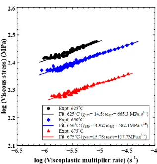
The viscous parameters at the selected temperatures are obtained by plotting vs. based on Cottrel’s stress partition [25] from the stress relaxation region of the DWT data such that , as shown in Fig. 5 and Fig. 6. It is worth noting that the rate of the viscoplastic multiplier, , is considered to be equal to .
The isotropic softening parameters, and , are identified by plotting the drag stress, , vs. the viscoplastic multiplier, , estimated such that , where is for the number of cycles. Due to the continued cyclic softening observed in the MarBN steel behavior, the saturated value of softening, , is taken to be the isotropic stress, R, just prior to the onset of failure. The parameter, , which describes the decay-rate of R, is fitted to the experimental data, as illustrated in Fig. 7(a). In addition, the kinematic hardening parameters are obtained from the process outline in [6, 18, 30]. To do so, the hardening parameters, and , associated with the second component, , are identified from the intercept and the slope of vs. the viscoplastic strain, . Assuming that the first back-stress has a negligible effect on the later hardening, the process is then repeated to determine and by plotting
vs. the viscoplastic strain, , for the initial stages of hardening, as presented in Fig. 7(b). It is worth noting that the focus of the current work is confined to the
1 2 3 4 5 6 7 8 9 10 11 12 13 14 15 16 17 18 19 20 21 22 23 24 25 26 27 28 29 30 31 32 33 34 35 36 37 38 39 40 41 42 43 44 45 46 47 48 49 50 51 52 53 54 55 56 57 58 59 60 61
investigation of the MarBN steel behavior until the “supposed” stabilized cycle, thereby the damage mechanisms are not captured by the constitutive model.
3.3. Calibration of the viscoplastic constitutive model
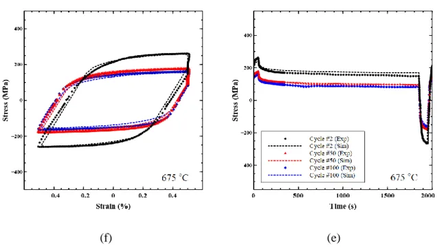
The capability of the proposed unified viscoplastic model is further checked via the predicted stress-strain hysteresis loops, by uniaxial implementation of the model within a standalone multi-axial UMAT code [30, 31], for a strain-rate of 0.01 %/s and an applied strain-range of ±0.5 %. The results in Figs. 8(a), (c) and (f) show the ability of the model to predict the mechanical responses at the selected test temperatures by comparing the predicted hysteresis loops to the DWT experimental data at the 2nd, 50th and 100th cycles, respectively. Figs. 8(b), (d) and (e) compare the simulated temporal stress evolution with the DWT experimental data for the selected fatigue cycles. The results show an excellent agreement with the experimental data; the model captures both the decelerated relaxation behavior and cyclic softening. Linear relationships of the material parameters with respect to the test temperatures were thus considered and summarised in Table 3. These formulations were then chosen to carry out the FE analyses for the superheater header. The P91 parameters under subcritical conditions were obtained from the authors’ previous works [25, 26].
4. Methodology for multi-axial service-life prediction 4.1. Thermomechanical loading histories
The main objective of the current work is i) to provide a service-life prediction strategy for a superheater steam header at the critical locations subjected to complex thermomechanical loading, and ii) to evaluate and then compare the high temperature mechanical performances of both P91 and MarBN headers under subcritical and USC conditions, respectively. Fig. 9(a) illustrates five typical thermomechanical cycles from operating plant showing
1 2 3 4 5 6 7 8 9 10 11 12 13 14 15 16 17 18 19 20 21 22 23 24 25 26 27 28 29 30 31 32 33 34 35 36 37 38 39 40 41 42 43 44 45 46 47 48 49 50 51 52 53 54 55 56 57 58 59 60 61
dependent steam temperature and pressure histories obtained just downstream from an Électricité de France
(
EDF)
superheater outlet header.A simplified representative cycle is proposed in Fig. 9(b). This idealised cycle is used hereafter to capture the salient features of loading histories for the assessment of subsequent deformation behavior of a high temperature pressurised steam header. The initial part of the ‘representative’ cycle simulates a starting-up and the corresponding temperature increases from 181°C to 467°C after 2.5 hours. This first part is followed by an exceptional cooling-down between 2.5 hours and 4.65 hours, when sudden reductions in steam temperature occur. Then, a dwell plateau of ~17 hours occurs, hovering around a mean value of approximately 550°C with ±10°C fluctuation. The temperature subsequently returns to 438°C after 5.7 hours with linear cooling-rates. The steam pressure history follows almost the identical pattern as the temperature history (in-phase), initially increasing from 0 to 15.9MPa over 8.75 hours with short dwell periods. The pressure is then held almost constant for 15 hours during which the temperatures eventually stabilize. When the power plant enters cool-down phase the pressure decreases to 0 over 1 hour as the plant shuts down. The idealised load profile without consideration of the frequent thermal transients during dwell periods, as given in Fig. 9(b), will be coupled within the FE analysis.
Different combinations of internal pressure and thermal cycle conditions are considered during the FE modelling in order to assess the high temperature performance of both P91 and MarBN headers:
(i) Typical flexible operating condition for the maximum pressure and temperature of 15.9MPa and 550°C for P91, referred to as ‘subcritical’ operating conditions based on the loading cycle in Fig. 9(b).
1 2 3 4 5 6 7 8 9 10 11 12 13 14 15 16 17 18 19 20 21 22 23 24 25 26 27 28 29 30 31 32 33 34 35 36 37 38 39 40 41 42 43 44 45 46 47 48 49 50 51 52 53 54 55 56 57 58 59 60 61
(ii) Scaling the subcritical operating conditions (same loading pattern as shown in Fig. 9(b)) with a significant increase in peak operating pressure and temperature of 22MPa and 650°C [34] for MarBN steel operating in future ‘USC’ conditions.
4.2. Finite element model of steam header
The calibrated material model and the idealised loadings were then applied to a serviced-aged superheater header which was retired from service after 141,000 operational hours with around 3,300 starting-up operations (flexible operation under the subcritical condition [3, 4]). The main dimensions of the header are shown in Fig. 10(a), with outlet diameter and thickness of 314mm and 33mm, respectively [4]. The header consists of a branch-pipe and eight stub-pipes oriented at interval 36° with the vertical branch-pipe. The details of the mesh refinement for the final FE model are highlighted in Fig. 10(a), consisting of 56,400 eight-node linear brick elements (C3D8 in ABAQUS) with a smallest element size of approximately 2mm. A prior detailed mesh sensitivity study was conducted to establish converged viscoplastic stresses. In contrast to a significantly more refined fine mesh, only 0.1% stress difference was found relative to the chosen mesh in Fig. 10(a). Specific constraint conditions were also applied and illustrated in Fig. 10(b). The heat transfer parameters for the thermomechanical analysis, i.e. thermal conductivity and specific heat, obtained from [35] have been given in Table 4. Idealised pressure was applied to the inner surfaces, and axial pressure thrusts were applied to the stub-end and branch-end. The header under flexible operations was analysed via the anisothermal unified viscoplastic constitutive material model described in Section 3.1. A monolithic structure of the superheater header was assumed in the present work due to the lack of experimental data of the welded MarBN steel. For readers interested in the FE extension to welded branched connections via multi-material modelling, more details and references are given in the authors’ previous work [6].
1 2 3 4 5 6 7 8 9 10 11 12 13 14 15 16 17 18 19 20 21 22 23 24 25 26 27 28 29 30 31 32 33 34 35 36 37 38 39 40 41 42 43 44 45 46 47 48 49 50 51 52 53 54 55 56 57 58 59 60 61
Multi-axial fatigue life prediction approaches can be summarized into three categories, namely equivalent stress-strain criterion, energy criterion and critical plane criterion [36]. Smith, Watson, and Topper (SWT) [37] had proposed an approach to evaluate multi-axial loading for materials with initial cracking by combining the cyclic maximum principal strain amplitude and maximum principal stress. This approach employs the maximum normal strain plane as the critical plane, which has been widely used in the service-life prediction of engineering structures. For example, O'Halloran et al. [38] recently introduced a surface damage factor in conjunction with critical-plane SWT approach to predict the minimum numbers of cycles to failure of marine risers. The form of the SWT parameter can be expressed as follows:
, (8) where and are the maximum principal stress and maximum principal strain-range on the critical plane, respectively, which are used to estimate the component life such that
, (9)
where E is the Young’s modulus, and stand for the fatigue strength and fatigue strength exponent, respectively, while and are the fatigue ductility coefficient and fatigue ductility exponent.
Under flexible operation, the dwell period between t2 and t3 (Fig. 9(b)) can be regarded as the dominant phase for one representative cycle. Therefore, one can use the Coffin-Manson and Basquin constants of test data at 650°C for the USC condition of MarBN steel and 550°C for the subcritical condition of P91 steel in order to carry out a conservative service-life assessment of the investigated header structure under multi-axial loading conditions. The values of Coffin-Manson and Basquin parameters for MarBN steel at 650°C and for the P91
1 2 3 4 5 6 7 8 9 10 11 12 13 14 15 16 17 18 19 20 21 22 23 24 25 26 27 28 29 30 31 32 33 34 35 36 37 38 39 40 41 42 43 44 45 46 47 48 49 50 51 52 53 54 55 56 57 58 59 60 61
steel at 550°C were obtained from the experimental test data of O'Hara et al. [14] and R. Kannan et al. [39] as illustrated in Fig. 11. These parameters are given in Table 5.
5. Results and discussion
The USC condition for MarBN steel with the identified parameters is first adopted in order to study the viscoplastic deformation behavior and to identify the failure locations of the superheater header. To better examine the critical regions within the superheater header, the predicted contour plots for both the maximum principal stresses and viscoplastic multiplier, , are presented in Fig. 12 and Fig. 13.
Fig. 12 shows the spatial distribution of the maximum principal stress from the USC analysis conducted on MarBN steel, which are selected at the critical time points t1 and t4 illustrated in Fig. 9(b). It can be seen from Fig. 12(a) that minor thermal-stress concentrations are observed at the inner-bore crotch regions of both branch-pipe and stub-pipes at the initial starting up cycle (close to t1). With the continued pressure and temperature increasing until t2, the peak stresses move to the inner-bore saddle regions on the inside surface, as can be seen in Fig. 12(b). Followed by 15 hours’ dwell-period at full loads, the peak stress slightly decreases from ~251.9MPa at t2 to ~221.5MPa at t3 of Fig. 12(c), due to the applied stress relaxation in the constitutive material model. However, as the operation goes through the shutdown phase, a significant thermal-stress is obtained both at the inner-bore crotch regions on the inside surface and the weld-toe saddle regions on the outside surface, as illustrated in Fig. 12(d). This observation is consistent with the work reported by [5, 20], where regions around the pipe penetration on the outside surface of the thick-walled header experience large thermal-stress, due to rapid changes in the steam temperature, leading to ligament cracking at sites between bore holes. It is also of great importance to investigate the viscoplastic multiplier, ,
1 2 3 4 5 6 7 8 9 10 11 12 13 14 15 16 17 18 19 20 21 22 23 24 25 26 27 28 29 30 31 32 33 34 35 36 37 38 39 40 41 42 43 44 45 46 47 48 49 50 51 52 53 54 55 56 57 58 59 60 61
spatial-temporal distributions, as a fatigue indicator parameter for crack initiation prediction for the header component [6, 20, 40]. Fig. 13 shows the viscoplastic multiplier, , distribution at time t4 at the end of shutdown phase. It can be clearly observed that viscoplastic multiplier displays concentrated regions with dissimilar magnitudes at the inner-bore saddle regions, indicating the ligament cracking can occur in the weld regions of the pipe penetration through the shell on the inside of the header. Based on the FE analysis, inner-bore and weld-toe saddles at both branch-pipe and stub-pipe are selected for the latter service-life prediction. Noted that the superheater header of P91 under subcritical condition shows the similar distribution as shown in Figs. 12 and 13.
To further examine this issue and to quantify the trends of maximum principal stress and strain illustrated in the contour plots for the component life prediction, Figs.14(a) ~ (d) present the temporal profile of the maximum principal stresses and strains during the representative cycle at the predicted critical locations, as illustrated in Figs. 12 and 13. For the branch inner-bore saddle region, the maximum principal stress shows a rapid increase to 135MPa when the inter-pressure is around 9.6MPa at the beginning of the heating up phase, with an initial maximum principal thermal-strain of about 0.25%. The stress then exhibited fluctuations before the loading goes through the stabilized dwell period between t2 and t3,as shown in Figs. 9(b) and (c). During the 15 hours’ hold period with maximum internal loads the maximum principal stress at the branch inner-bore saddle region decreases from ~225 MPa to ~200MPa due to the stress relaxation induced by the introduction of viscous effect in the material model as shown in Fig. 14(a), concomitantly this effect is significantly extenuated at the stub-pipe inner-bore saddle region, see Fig. 14(c). However, the similar stress relaxation behavior cannot be observed at the weld-toe saddle regions of branch-pipe and stub-tubes during the short hold period as illustrated in Figs. 14(b) and (d). Significant thermal-strain can be observed at all regions during the shutdown phase, almost twofold
1 2 3 4 5 6 7 8 9 10 11 12 13 14 15 16 17 18 19 20 21 22 23 24 25 26 27 28 29 30 31 32 33 34 35 36 37 38 39 40 41 42 43 44 45 46 47 48 49 50 51 52 53 54 55 56 57 58 59 60 61
larger than the magnitudes of the initial heating up phase. Similar tendencies are observed for the P91 header at these locations under the same loading patterns of the subcritical condition, as illustrated in Fig. 15. The predicted maximum principal stress and strain-range at the four locations in Fig. 14 and Fig. 15 is coupled with SWT approach to assess the fatigue crack initiation (FCI) of headers, which gives a reasonable comparison with industrial experience as tabulated in Table 6 on the assumption of 292 starting-up cycles per year.
6. Conclusions and future work
A temperature-dependent unified viscoplasticity model incorporating the interactions of the viscous effect with cyclic softening and kinematic hardening is presented in this work and applied to the multi-axial modelling of a critical fossil-fired power plant component. The proposed methodology successfully links the idealised loading histories of flexible operation at high temperature, uniaxial high temperature experimental fatigue data, and SWT approach together, in order to predict the potential premature failure locations and estimate the lifetime at component level compared with the industrial report. The key conclusions obtained are:
Identification and calibration of cyclic constitutive viscoplastic parameters of MarBN from uniaxial high temperature LCF and CFI experimental tests over a range of temperatures coupling with the unified viscoplasticity model have facilitated new insights into the mechanical deformation behaviors of MarBN component in the power plant under flexible thermomechanical operations for future application. The predicted results under both subcritical and USC conditions indicate that initial
thermal-stress and strain of header concentrate at the inner-bore crotch regions during the heating up phase, while these regions migrate to the inner-bore saddle regions on the inside surface when the operation comes into stabilized phase. The stress relaxation effect can only be observed at inner-bore saddle regions. During the
1 2 3 4 5 6 7 8 9 10 11 12 13 14 15 16 17 18 19 20 21 22 23 24 25 26 27 28 29 30 31 32 33 34 35 36 37 38 39 40 41 42 43 44 45 46 47 48 49 50 51 52 53 54 55 56 57 58 59 60 61
shutdown phase, the thermal-stress and strain concentration are found to be located at the inner-bore crotch regions and the weld-toe saddle regions. The branch inner-bore saddle region is shown to be more detrimental in contrast with the regions at stub-pipes.
The FCI of P91 header under subcritical condition is shown to correlate well with the industrial experience at the most critical location of branch inner-bore saddle. In addition, The FCI on the outside surface is predicted to be longer than that of the inside surface. The header of MarBN under USC condition is shown to have a comparable service-life performance compared to P91 header under subcritical condition even the maximum operating steam loading increase significantly.
The occurrence of the weldments is detrimental to the service-life of the power plant connections due to the thermal-gradient induced material inhomogeneity [41]. Thus, it is important in our future to experimentally characterize the microstructure features, as well as the mechanical properties for the welded MarBN through small-scale test [41, 42, 43], coupled with our physical modelling technics [41] to enhance the fundamental understanding of the high temperature performance of 9Cr steel.
Acknowledgments
This work is supported by the Engineering and Physical Sciences Research Council (grant numbers: EP/N509991/1, EP/K021095/1 and EP/N509942/1). Acknowledgments also go to Mr. Shane Maskill at the University of Nottingham for his support in the experimental testing.
References:
1. Alizadeh, M. I., Moghaddam, M. P., Amjady, N., Siano, P., Sheikh-El-Eslami, M. K., (2016). “Flexibility in future power systems with high renewable penetration: A review,” Renewable & Sustainable Energy Reviews, 57:1186-1193.
1 2 3 4 5 6 7 8 9 10 11 12 13 14 15 16 17 18 19 20 21 22 23 24 25 26 27 28 29 30 31 32 33 34 35 36 37 38 39 40 41 42 43 44 45 46 47 48 49 50 51 52 53 54 55 56 57 58 59 60 61
2. Zhao, Y. L., Fan, P. P., Liu, M., Chong, D. T., Yan, J. J., (2019). “Fatigue Lifetime Estimation of a Heater in Coal-Fired Power Plants Under a Flexible Operational Framework-Regulating Extraction Steam of High-Pressure Heaters,” Innovative Solutions for Energy Transitions, 158: 5225-5230.
3. Viswanathan, R., J. F. Henry, J. Tanzosh, G. Stanko, J. Shingledecker, B. Vitalis and R. Purgert, (2005). “U.S. Program on Materials Technology for Ultra-Supercritical Coal Power Plants.” Journal of Materials Engineering and Performance 14(3): 281-292.
4. EDF company, Western Burton power plant report, 2016.
5. T. P. Farragher, S. Scully, N. P. O’Dowd, S. B. Leen, (2013). “Development of life assessment procedures for power plant headers operated under flexible loading scenarios,” International Journal of Fatigue, 49: 50-61.
6. M. Li, R. A. Barrett, S. Scully, N. M. Harrison, S. B. Leen and P. E. O'Donoghue, (2016). “Cyclic plasticity of welded P91 material for simple and complex power plant connections.” International Journal of Fatigue 87: 391-404.
7. D. F. Li, R. A. Barrett, P. E. O'Donoghue, C. J. Hyde, N. P. O’Dowd, S. B. Leen, (2016). “Micromechanical finite element modelling of thermo-mechanical fatigue for P91 steels,” International Journal of Fatigue, 87:192-202.
8. A. Nagesha, R. Kannan, G.V.S. Sastry, R. Sandhya, V. Singh, K. Bhanu Sankara Rao, M. D. Mathew, (2012). “Isothermal and thermomechanical fatigue studies on a modified 9Cr–1Mo ferritic martensitic steel,” Materials Science and Engineering: A, 554: 95-104.
9. R. A. Barrett, C. J. Hyde, P. E. O'Donoghue, S. B. Leen, (2019). “Thermomechanical fatigue in 9-12Cr steels: Life prediction models and the effect of tensile dwell periods,” International Journal of Fatigue, 126: 335-345.
1 2 3 4 5 6 7 8 9 10 11 12 13 14 15 16 17 18 19 20 21 22 23 24 25 26 27 28 29 30 31 32 33 34 35 36 37 38 39 40 41 42 43 44 45 46 47 48 49 50 51 52 53 54 55 56 57 58 59 60 61
10. Abe, F., Tabuchi, M., Semba, H., Yoshizawa, M., Komai, N., Fujita, A.,(2008). “Feasibility of MARBN steel for application to thick section boiler components in USC power plant at 650 °C,” in Proceedings of the 5th International Conference on Advances in Materials Technology for Fossil Power Plants, 92-106.
11. R. A. Barrett, E. M. O'Hara, P. E. O'Donoghue, S. B. Leen, (2016). “High-Temperature Low-Cycle Fatigue Behavior of MarBN at 600 °C,” Journal of Pressure Vessel Technology, 138.
12. A. Benaarbia, X. Xu, W. Sun, A. A. Becker, M. A. E., Jepson,(2018). “Investigation of short-term creep deformation mechanisms in MarBN steel at elevated temperatures,” Materials Science and Engineering A, 734:491-505.
13. A. Benaarbia, X. Xu, W. Sun, A. A. Becker, S. Osgerby, (2020). “Characterization of cyclic behavior, deformation mechanisms, and microstructural evolution of MarBN steels under high temperature conditions,” International Journal of Fatigue, 131: 105270.
14. E. M. O'Hara, “An experimental and computational investigation of the high temperature behaviour of MarBN steel with application to effects of manufacturing,” National University of Ireland, Galway, Ph.D. Thesis, 2018.
15. E. M. O'Hara, N. M. Harrison, B. K. Polomski, R. A. Barrett, S. B. Leen, (2017). “Fatigue damage characterisation of MarBN steel for high temperature flexible operating conditions,” Part L-Journal of Materials-Design and Applications, 231: 23-37.
16. E. M. O'Hara, N. M. Harrison, B. K. Polomski, R. A. Barrett, S. B. Leen, (2018). “The effect of inclusions on the high-temperature low-cycle fatigue performance of cast MarBN: Experimental characterisation and computational modelling,” Fatigue & Fracture of Engineering Materials & Structures, 41: 2288-2304.
1 2 3 4 5 6 7 8 9 10 11 12 13 14 15 16 17 18 19 20 21 22 23 24 25 26 27 28 29 30 31 32 33 34 35 36 37 38 39 40 41 42 43 44 45 46 47 48 49 50 51 52 53 54 55 56 57 58 59 60 61
17. X. W. Wang, W. Zhang, J. M. Gong, M. A. Wahab, (2018). “Low cycle fatigue and creep fatigue interaction behavior of 9Cr-0.5Mo-1.8W-V-Nb heat-resistant steel at high temperature,” Journal of Nuclear Materials, 505: 73-84.
18. S. L. Zhang, and F. Z. Xuan, (2017). “Interaction of cyclic softening and stress relaxation of 9–12% Cr steel under strain-controlled fatigue-creep condition: Experimental and modeling,” International Journal of Plasticity, 98: 45-64.
19. B. Fournier, M. Salvi, F. Dalle, Y. De Carlan, C. Caës, M. Sauzay, A. Pineau, (2010). “Lifetime prediction of 9–12%Cr martensitic steels subjected to creep–fatigue at high temperature,” International Journal of Fatigue, 32: 971-978.
20. J. P. Rouse, P. Zacharzewski, C. J. Hyde, R. Jefferson-Loveday, A. Morris, S. T. Kyaw, (2018). “A case study investigation into the effects of spatially dependent convection coefficients on the fatigue response of a power plant header component,” International Journal of Fatigue, 113: 137-148.
21. R. Vetri Selvan, P. Sathiya, K. Devakumaran, G. Ravichandran, (2019) “The effect of ligament size on the thermal fatigue life of 9Cr 1Mo steel boiler header under cold, warm and hot starts,” Engineering Failure Analysis, 97: 727-739.
22. N. Islam, D. J. Dewees, M. Cooch, T. Hassan, (2017). “Creep-Fatigue Damage Evaluation of Modified Grade 91 Headers Using Damage Coupled Unified Viscoplastic Model,” ASME Pressure Vessels and Piping Conference.
23. D. F. Li, B. J. Golden, and N. P. O'Dowd, (2014). “Multiscale modelling of mechanical response in a martensitic steel: A micromechanical and length-scale-dependent framework for precipitate hardening,” Acta Materialia, 80: 445-456.
24. F. W. Sun, E. D. Meade, and N. P. O'Dowd, (2018). “Microscale modelling of the deformation of a martensitic steel using the Voronoi tessellation method,” Journal of the Mechanics and Physics of Solids, 113: 35-55.
1 2 3 4 5 6 7 8 9 10 11 12 13 14 15 16 17 18 19 20 21 22 23 24 25 26 27 28 29 30 31 32 33 34 35 36 37 38 39 40 41 42 43 44 45 46 47 48 49 50 51 52 53 54 55 56 57 58 59 60 61
25. A. A. Saad, “Cyclic plasticity and creep of power plant materials. ,” University of Nottingham, Ph.D. Thesis 2012.
26. A. A. Saad, T. H. Hyde, W. Sun, C. J. Hyde, D. W. J. Tanner, (2013). “Characterization of viscoplasticity behaviour of P91 and P92 power plant steels,” International Journal of Pressure Vessels and Piping, 111: 246-252.
27. J. L. Chaboche,(1977). “Viscoplastic Constitutive Equations for the Description of Cyclic and Anisotropic Behaviour of Metals, Bulletin de L'Academie Polonaise des Sciences,” Serie des Sciences Techniques, 25: 33.
28. J. L. Chaboche, (2008). “A review of some plasticity and viscoplasticity constitutive theories,” International Journal of Plasticity, 24:1642-1693.
29. A. Benaarbia, J. P. Rouse, and W. Sun, (2018). “A thermodynamically-based viscoelastic-viscoplastic model for the high temperature cyclic behaviour of 9–12% Cr steels,” International Journal of Plasticity, 107:100-121.
30. A. Benaarbia, Y. Rae, and W. Sun,(2018). “Unified viscoplasticity modelling and its application to fatigue-creep behaviour of gas turbine rotor,” International Journal of Mechanical Sciences, 136: 36-49.
31. Y. Rae, A. Benaarbia, J. Hughes, W. Sun, (2019). “Experimental characterisation and computational modelling of cyclic viscoplastic behaviour of turbine steel,” International Journal of Fatigue, 124: 581-594.
32. Abaqus (2016), Dassault Systemes Simulia Corp.
33. J. Lemaitre, J., Chaboche, Mechanics of solid materials. UK: Cambridge University Press; 1990.
34. F. Abe, (2011). “Effect of Boron on Microstructure and Creep Strength ofAdvanced Ferritic Power Plant Steels,” Procedia Engineering, 10: 94-99.
1 2 3 4 5 6 7 8 9 10 11 12 13 14 15 16 17 18 19 20 21 22 23 24 25 26 27 28 29 30 31 32 33 34 35 36 37 38 39 40 41 42 43 44 45 46 47 48 49 50 51 52 53 54 55 56 57 58 59 60 61
35. A. H. Yaghi, T. H. Hyde, A. A. Becker, J. A. Williams, W. Sun, (2005). “Residual stress simulation in welded sections of P91 pipes,” Journal of Materials Processing Technology, 167: 480-487.
36. J. Das, and S. M. Sivakumar, (1999). “An evaluation of multiaxial fatigue life assessment methods for engineering components,” International Journal of Pressure Vessels and Piping, 76:741-746.
37. K. N. Smith, P. Watson T. H. Topper, (1970). “A stress–strain function for the fatigue of metals,” Defense Technical Information Center.
38. S. M. O'Halloran, A. D. Connaire, A. M. Harte, S. B. Leen, (2020). “A global-local fretting analysis methodology and design study for the pressure armour layer of dynamic flexible marine risers,” Tribology International, 142:105967.
39. R. Kannan, V. Sankar, R. Sandhya, M. D. Mathew, (2013) “Comparative Evaluation of the Low Cycle Fatigue Behaviours of P91 and P92 Steels,” 6th International Conference on Creep, Fatigue and Creep-Fatigue Interaction, 55:149-153.
40. C. A. Sweeney, B. O'Brien, F. P. E. Dunne, S. B. Leen, (2014). “Strain-gradient modelling of grain size effects on fatigue of CoCr alloy,” Acta Materialia, 78: 341-353.
41. Li, M., Sun, F. W., Li, D. F., P. E. O’Donoghue, N. P. O’Dowd, S. B. Leen, (2018). “The effect of ferrite phases on the micromechanical response and crack initiation in the inter-critical heat-affected zone of a welded 9Cr martensitic steel”, Fatigue & Fracture of Engineering Materials & Structures, 41: 1245-1259.
42. T.H. Hyde, W. Sun, (2000). “Determining High Temperature Properties of Weld Materials,” J. Strain Analysis, 43: 408-414.
43. T. H. Hyde, B. S M Ali, W. Sun, (2013). “Interpretation of small ring creep test data,” J. Strain Analysis, 48:269-278.
1 2 3 4 5 6 7 8 9 10 11 12 13 14 15 16 17 18 19 20 21 22 23 24 25 26 27 28 29 30 31 32 33 34 35 36 37 38 39 40 41 42 43 44 45 46 47 48 49 50 51 52 53 54 55 56 57 58 59 60 61 Table:
Table 1: Chemical composition of the investigated tempered MarBN (all elements are in wt.%, B and N are in ppm).
Table 2: The selected experimental tests conducted on MarBN and P91 steels [13, 25, 26]. Material Strain-range △ (%) Strain-rate (%) Temperature (°C) Waveforms MarBN ±0.5 0.01 400 SWT 625, 650, 675 SWT, DWT P91 [25, 26] 400, 500, 600 SWT, DWT
1 2 3 4 5 6 7 8 9 10 11 12 13 14 15 16 17 18 19 20 21 22 23 24 25 26 27 28 29 30 31 32 33 34 35 36 37 38 39 40 41 42 43 44 45 46 47 48 49 50 51 52 53 54 55 56 57 58 59 60 61
Table 3: The fitted equations used in the constitutive material model for the MarBN and P91 steels based on the identified material parameters at isothermal conditions.
Parameter
scopes Material parameters P91 [25, 26] MarBN
Elastic Young’s Modulus, E (MPa) -76.1T + 219163 -125.3T + 218950 Initial cyclic yield stress, k (MPa) -0.48T + 399.7 -1.3T + 968.7 Non-linear
viscosity
Viscoplastic resistance,
(MPa.s1/n) -5.76T + 4209 -3.6T + 2699.8
Viscous component, (-) 0.26e0.0047T 0.47e0.004T
Isotropic & Kinematic
hardening
Saturated softening value, (MPa) -0.055T - 29.8 0. 6T – 520 Softening decay-rate, (-) 0.0035T – 0.55 0. 02T – 12.77
Back-stress-1, (MPa) 0.06T + 38.7 0.018T + 43.7 Rate of decay-1, (-) -0.42T + 3697 -37.7T + 39282 Back-stress-2, (MPa) -0.39T + 319.3 -0.14T + 177
Rate of decay-2, (-) -0.21T + 531 2.0T + 54.8
Table 4: Temperature-dependent heat transfer parameters used in the FE model of the investigated steam header for 9Cr steels [35].
Temperature (°C) Density g/m3 Thermal conductivity (W/m·K) Specific heat (J/kg·K) 150 7.86 26.9 490 200 27.5 510 250 530 300 550 350 29.2 570 400 600 450 630 500 30.2 660 550 710 600 770 650 860 700 31.5 942
1 2 3 4 5 6 7 8 9 10 11 12 13 14 15 16 17 18 19 20 21 22 23 24 25 26 27 28 29 30 31 32 33 34 35 36 37 38 39 40 41 42 43 44 45 46 47 48 49 50 51 52 53 54 55 56 57 58 59 60 61
Table 5. Basquin and Coffin-Manson parameters for the MarBN steel at 650°C and for the P91 steel at 550°C used to assess the lifetime of the investigated header structure under
multi-axial loading conditions. Material Temperature (°C) (MPa) E (MPa) MarBN 650 554 -0.192 0.376 -0.386 151151 P91 550 424.6 -0.171 0.21 -0.371 179354
Table 6: Life prediction of headers for FCI at different locations for both 9Cr steels under the subcritical and USC conditions using the SWT approach.
Material Conditions Header Locations FCI (cycles)
FCI (years)
Unit Avg. life (years) MarBN USC Branch-pipe Weld-toe saddle 21995 75.3 - Inner-bore saddle 2734 9.36 Stub-pipe Weld-toe saddle 19754 67.6 Inner-bore saddle 6009 20.9 P91 subcritical Branch-pipe Weld-toe saddle 19447 66.6 16.1[4] Inner-bore saddle 3032 10.4 Stub-pipe Weld-toe saddle 19809 67.8 Inner-bore saddle 5637 19.3
1 2 3 4 5 6 7 8 9 10 11 12 13 14 15 16 17 18 19 20 21 22 23 24 25 26 27 28 29 30 31 32 33 34 35 36 37 38 39 40 41 42 43 44 45 46 47 48 49 50 51 52 53 54 55 56 57 58 59 60 61 Figures:
Fig. 1: Typical unit average starts over 21 years for a UK conventional fossil-fired power plant.
Fig. 2: The experimental setup based on Tinius Olsen H25KS electromechanical testing machine consisting of a ±25 kN pancake style load cell and a Severn Thermal Solutions
1 2 3 4 5 6 7 8 9 10 11 12 13 14 15 16 17 18 19 20 21 22 23 24 25 26 27 28 29 30 31 32 33 34 35 36 37 38 39 40 41 42 43 44 45 46 47 48 49 50 51 52 53 54 55 56 57 58 59 60 61 (a) (b) (c)
Fig. 3: (a) Dimensions of the investigated specimens (mm); (b) DWT loading pattern used for the CF experiments, and (c) SWT loading pattern used for the LCF experiments.
1 2 3 4 5 6 7 8 9 10 11 12 13 14 15 16 17 18 19 20 21 22 23 24 25 26 27 28 29 30 31 32 33 34 35 36 37 38 39 40 41 42 43 44 45 46 47 48 49 50 51 52 53 54 55 56 57 58 59 60 61 (c)
Fig. 4: Comparisons of measured results of MarBN between SWT and DWT at 625°C (a) Stress-strain responses for the initial cycle, (b) Stress-strain responses for the half-life cycle,
(c) Cyclic evolution of maximum stress for SWT and DWT tests, respectively.
Fig. 5: Schematic hysteresis loops for both SWT and DWT with tensile hold periods, showing the Cottrel’s stress partition.
1 2 3 4 5 6 7 8 9 10 11 12 13 14 15 16 17 18 19 20 21 22 23 24 25 26 27 28 29 30 31 32 33 34 35 36 37 38 39 40 41 42 43 44 45 46 47 48 49 50 51 52 53 54 55 56 57 58 59 60 61
Fig. 6: Identification of the viscous parameters for the MarBN steel at the three selected temperatures based on the DWT data.
(a) (b)
Fig. 7: Identification of the (a) isotropic parameters, and (b) kinematic hardening parameters for the MarBN steel at the three selected temperatures.
1 2 3 4 5 6 7 8 9 10 11 12 13 14 15 16 17 18 19 20 21 22 23 24 25 26 27 28 29 30 31 32 33 34 35 36 37 38 39 40 41 42 43 44 45 46 47 48 49 50 51 52 53 54 55 56 57 58 59 60 61 (a) (b) (c) (d)
1 2 3 4 5 6 7 8 9 10 11 12 13 14 15 16 17 18 19 20 21 22 23 24 25 26 27 28 29 30 31 32 33 34 35 36 37 38 39 40 41 42 43 44 45 46 47 48 49 50 51 52 53 54 55 56 57 58 59 60 61 (f) (e)
Fig. 8: The predicted and experimental hysteresis responses of the MarBN steel at 625°C, 650°C and 675°C, respectively, highlighting the capability of the current model to capture the cyclic softening, the hysteresis area reduction and the stress relaxation behavior. The strain-rate was set at 0.01%s-1 while the hold period at 30mins.
(a) (b)
Fig. 9: (a) Operational boiler outlet steam temperature and pressure conditions for a conventional fossil-fired unit, and (b) An idealised loading profile of the 1st cycle in Fig. 9(a) used for the FE simulations.
1 2 3 4 5 6 7 8 9 10 11 12 13 14 15 16 17 18 19 20 21 22 23 24 25 26 27 28 29 30 31 32 33 34 35 36 37 38 39 40 41 42 43 44 45 46 47 48 49 50 51 52 53 54 55 56 57 58 59 60 61 (a) (b)
Fig. 10: (a) The FE mesh with the main dimensions of the steam header in a conventional fossil-fired power plant, (b) Boundary conditions used for the FE analyses.
Fig. 11: Identification of Coffin-Manson and Basquin parameters for MarBN at 650°C and P91 at 550°C.
1 2 3 4 5 6 7 8 9 10 11 12 13 14 15 16 17 18 19 20 21 22 23 24 25 26 27 28 29 30 31 32 33 34 35 36 37 38 39 40 41 42 43 44 45 46 47 48 49 50 51 52 53 54 55 56 57 58 59 60 61 (a) (b) (c) (d)
Fig. 12: Predicted spatio-temporal distributions of the maximum principal stress during the representative cycle at different selected stages as illustrated in Fig. 9(b): (a) t1, (b) t2, (c) t3
1 2 3 4 5 6 7 8 9 10 11 12 13 14 15 16 17 18 19 20 21 22 23 24 25 26 27 28 29 30 31 32 33 34 35 36 37 38 39 40 41 42 43 44 45 46 47 48 49 50 51 52 53 54 55 56 57 58 59 60 61
Fig. 13: Predicted viscoplastic multiplier, , distribution at the end of representative cycle, indicating the premature failure initiates at the weld regions from pipe penetration on the
inside surface.
1 2 3 4 5 6 7 8 9 10 11 12 13 14 15 16 17 18 19 20 21 22 23 24 25 26 27 28 29 30 31 32 33 34 35 36 37 38 39 40 41 42 43 44 45 46 47 48 49 50 51 52 53 54 55 56 57 58 59 60 61 (c) (d)
Fig. 14: Maximum principle stress and strain temporal evolutions for the MarBN under the USC condition with the same loading pattern as shown in Fig. 9(b): (a) and (b) for branch inner-bore and weld-toe saddle regions, (c) and (d) for stub-pipe inner-bore and weld-toe saddle regions, respectively.
1 2 3 4 5 6 7 8 9 10 11 12 13 14 15 16 17 18 19 20 21 22 23 24 25 26 27 28 29 30 31 32 33 34 35 36 37 38 39 40 41 42 43 44 45 46 47 48 49 50 51 52 53 54 55 56 57 58 59 60 61 (c) (d)
Fig. 15: Maximum principle stress and strain temporal evolution for the P91 header subjected to the subcritical condition for loading pattern as given in Fig. 9(b): (a) and (b) for branch inner-bore and weld-toe saddle regions, (c) and (d) for stub-pipe inner-bore and weld-toe saddle regions, respectively.
![Table 2: The selected experimental tests conducted on MarBN and P91 steels [13, 25, 26]](https://thumb-eu.123doks.com/thumbv2/123doknet/7420072.218980/27.892.160.735.767.958/table-selected-experimental-tests-conducted-marbn-p-steels.webp)