To cite this version :
Samira SADEGHI, Mohsen SADEGHI, Ali SIADAT, Patrick MARTIN, William ZIZ - Intelligent feature based resource selection and process planning - Proceedings of the International Conference on PLM '10 - Vol. Chapter 3: Process Development, p.133-145 - 2012
Any correspondence concerning this service should be sent to the repository
Copyright © 2010 Inderscience Enterprises Ltd.
Intelligent feature based resource selection and
process planning
Samira Sadeghi
1, Mohsen Sadeghi
2, Ali
Siadat
1, Patrick Martin
1, William Ziz
21Laboratoire de Conception, Fabrication et Commande (LCFC) Arts et Metiers ParisTech
4 rue Augustin Fresnel, 57078 Metz Cedex 3, France Tel:0033387375430, Fax : 0033387375470
[email protected], Ali.Siadat @ensam.eu,
Patrick.Martin @ensam.eu
2ProctonLabs
180 Rue de Vaugirard. F-75015 Paris, France Tel: 0033177755257
[email protected], [email protected]
Abstract: This paper presents an intelligent knowledge-based integrated
manufacturing system using the STEP feature-based modeling and rule based intelligent techniques to generate suitable process plans for prismatic parts. The system carries out several stages of process planning, such as identification of the pairs of feature/tool that satisfy the required conditions, generation of the possible process plans from identified tools/machine pairs, and selection of the most interesting process plans considering the economical or timing indicators. The suitable processes plans are selected according to the acceptable range of quality, time and cost factors. Each process plan is represented in the tree format by the information items corresponding to their CNC Machine, required tools characteristics, times (machining, setup, preparatory) and the required machining sequences. The process simulation module is provided to demonstrate the different sequences of machining. After selection of suitable process plan, the G-code language used by CNC machines is generated automatically. This approach is validated through a case.
Keyword: Process planning, STEP, Knowledge based, integrated design,
manufacturing
1 Introduction
Integrated manufacturing modelling is the main subject of manufacturing environment design and computerized manufacturing support systems [1], [2]. Principal activities involved in the integrated manufacturing include product design, process design, suitable manufacturing process selection and planning [3].
The selection of a suitable machining process for a given set of product characteristics and requirements is one of the most significant and important issues in product development. The early process selection combined with product-process
compatibility analysis determines various parameters to integrate the diverse constraints imposed by different experts. This analysis is first and foremost based on the experimental knowledge of the experts. One of the important aspects of knowledge based integrated manufacturing design systems is the development of an adequate solution for representing and correlating different types of knowledge. The expert knowledge modeling facilitates the understanding of the complex interrelationships within integrated product-process model in product development.
The link between the product, its associated process and resource plan belongs to knowledge formalization. Experts use their knowledge to determine the selection of the manufacturing processes and associated resources or to define the product parameters considering the manufacturing and resources constraints.
Effective process selection for a given set of product characteristics & requirements is a multi-criterion problem which is strongly influenced by interdependent manufacturing knowledge like product knowledge (product complexity, design requirements, product quality) and resource knowledge (resource availability, characteristic and cost). Based on the information provided regarding the role and experiences of experts in product-process design this knowledge is formalized. The process-resource selection involves two steps: step 1 involves the evaluation of available processes for their technical capability in order to appropriately respond to design requirements and step 2 ranks the process performance with regard to its resource consumption economically [4]. Many methods have been proposed to support these steps. Ashby [5] proposes the selection of manufacturing processes considering their compatibility with the geometrical parameter and the resources needed followed by ranking of the relative costs associated. The final choice is performed with respect to the rating, industrial knowledge, and available manufacturing resources; however, the approach adopted in this research does not target a specific manufacturing domain.
To determine the sequences of specific manufacturing process, Lovatt [6] describes the framework based on the definition of process plan with different manufacturing tasks (steel cutting, steel heat treatment, casting, etc). The process selection is carried out by the combination of manufacturing process attributes, material parameters, and product specifications to satisfy design requirements [7]. The approach proposed by Gupta [8] consists of three phases: (1) identification of the pairs of material/process that satisfy the required conditions (economical and geometrical specifications), (2) generation of the possible process plans from identified material/process pairs, and (3) selection of the most interesting process plans considering the economical indicators. In Ishii’s work[9],[10], the process selection is decomposed into two steps: (1) the first step is the identification of relevant parameters that affect manufacturing processes selection and (2) the second step consists in developing the representation schemas for knowledge used during the manufacturing processes selection. This knowledge is used to determine compatibility between product specifications and process parameters in order to rank the possible manufacturing processes according to the performance of economical indicators more precisely. Boothroyd [11] propose the selection of the material/process pairs based on the process capability in terms of geometrical specifications realization and material constraint. The final selection is determined by the elimination of the unacceptable material/process pairs, considering the related constraints and predefined indicators, such as the cost.
In terms of integrated manufacturing systems, the feature-based approaches have been recognized as essential tools to integrate design and automated process planning. In this context, Devireddy [12] presented a methodology of integrating the design and planning of manufacturing by utilizing the concept of feature-based modeling. Khoshnevis [13] described architecture of an integrated process planning system, called 3I-PP, which is comprised of three modules: feature completion, process selection, and process sequencing. Berger [14] presents an approach for enabling the automatic preparation of STEP-NC based Workplans with methods known from graph theory. Based on that, it is possible to use algorithms to find the shortest path inside this directed graph as optimal sequenced solution under given requirements. Finally, the corresponding NC machining code will be generated and distributed to the machinery.
The research results presented in this paper contributes to knowledge-based integrated manufacturing support by development of a computerized system to process planning, utilizing the concepts of STEP feature-based modeling and rule based intelligent techniques. The suitable processes plans are selected according to the acceptable range of quality, time and cost factors. This approach is validated through a PPRint (Product, Process, Resource integrating) tool development and the application of a case study.
Table 1, summarizes the characteristics of different manufacturing process selection approaches.
Table 1 Comparison of the approaches “manufacturing processes selection”
Approach Choice of manufacturing process
Choice of
material Associated tool Economical evaluation
Ishii Yes No HyperQ Yes
Ashby Yes Yes CES n.a.
Gupta Yes Yes Seer-DFM Yes
Boothroyd Yes Yes DFMA Yes
Lovatt Yes n.a. n.a. Yes
Devireddy Yes No n.a. n.a.
Khoshnevis Yes Yes 3I-PP Yes
Berger Yes No n.a. n.a.
Sadeghi Yes Yes PPRint Yes
2 Knowledge within Process Planning
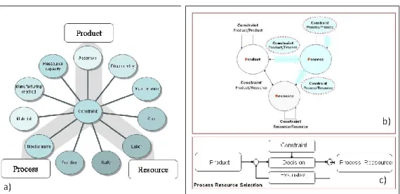
Integrated manufacturing is considered as a network of product, process and resource parameters and expert’s knowledge as a set of constraints [15] applied on the parametric network. In engineering, constraints are formalized as: special design requirements that must be satisfied; logic reasoning activity of experts; dependency between design functional requirements, design parameters and flow of information between experts to support interdisciplinary knowledge integration (figure 1-a).
Figure 1 constraint classification in the process planning
The design and related constraint representation provides an integrated product-process decision making approach to evaluate its consistency and is useful in selecting a suitable manufacturing process and product design parameters [16] (figure 1-c). Our main objectives are:
To provide an effective data representation model supporting the integration of different elements (product, processes, and resources) and analysis of relationships and related knowledge between them
Gather and integrate knowledge related to the product definition and the manufacturing process to control the whole production process, allowing us to produce a better product
Improving the exploitation of knowledge capital in new projects
Provide a basis for knowledge capitalization and reuse issued from different product development projects
So, constraint definition and classification are the key issues for this framework. We need to consider practical ways to represent design constraint in process planning environment.
Constraints in a process planning analysis can be simply classified into constraints inside each kind of entity model and constraints between different kinds of entity models according to the product, process and resources view [17] (figure 1-b):
Product: Product constraint that represents relationships between entities defined by product model, for example, constraints about dimension, geometry, tolerance, features, etc.
Process: Process constraint that represents relationships between entities defined by process model. For example, the dependency constraint between two sequences of machining operation
Resources: Resources constraint that represent relationships between entities defined by resource model. For example, availability, compatibility
Product/process constraint: such as constraint about product features property and process parameters to realized this features
Process/Resources constraint: for example, constraint about choice of tools for machining specific feature according to optimum manner, feature property, quality, cost and machining time
Product/ Resources constraint: for example the constraint about product property and resource characteristic (Product features vs. Machine accessibility)
The manufacturing process selection combined with product-process-resource compatibility analysis to determine the various parameters and steps as well as the correlation of requirement. The purpose is to find a path among several process planning obstacles that could lead to a better solution that satisfies the diverse requirement considering constraints imposed by different experts throughout the process planning. In manufacturing industries, this analysis is first and foremost based on the experimental knowledge of the experts.
The method we describe in this paper is based on the declaration and checking of expert’s knowledge (constraint) in order to check the coherency between product, process and resource elements.
With the definition of constraint categories, the system provides the suitable constraint verification. It allows specifying which constraint representation approach is possible for each element of data model.
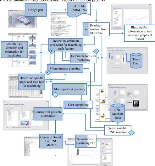
We consider following general steps which must be considered to cerate a suitable process plan (figure 2):
1. The step provides the environment to import the STEP file and to illustrate the product information which is necessary to analyze the coherent manufacturing process. It contains product constraint which defines the relationship between the elements of product in STEP standard.
2. The step determines optimum procedure for machining each feature according to feature characteristic, part material, tool life, available tool in data base and other constraint.
3. The step generate micro process planning according to optimum procedure for machining each feature, spindle speed and feed rate, possible tool direction and orientation for machining and other constraint.
4. The step generate macro process by considering the information about precedence machining feature, setup face, machining face, setup time, time of tool moving between each feature and time of tool changing.
5. The step presents the selection of coherent CNC machines and the optimum sequences of machining for each CNC machine. The features characteristic and the tool accessibility knowledge are the necessary elements to select the CNC machine.
6. The step presents the cost model for manufacturing process. It contains different costs for different process attributes: physical attributes such as the materials, the tolerance, size range, time, complexity of shape; and economic attributes such as tooling cost, and rate of production. This module is used to select the acceptable process identifying the cost value specified by the cost model. The effect is to eliminate the processes which cannot meet the specifications. The estimated cost and the time required for the selected process are displayed in the process plan, which is the output of this module.
7. The step is used to prepare the manufacturing process by generating the corresponding G-code for the CNC machine. To generate G-code, this module gets the process plans information as input
8. The step is used to simulate the machining sequences (process plan). Each step of simulation demonstrates the machining direction and the tool required to realize the feature.
Figure 2 The manufacturing process and resource selection process
Read part information from
STEP file
Determine tools for machining Design part STEP file (ARM 224) Select suitable CNC machine Macro process planning
Simulation of machining Part
Illustrate Part information in tree view and graphical
format
Tools Data
Determine spindle speed and feed rate for machining
CNC Machine
Data Determine optimum
procedure for machining each feature
Micro process planning Possible Tool
direction and orientation for machining
Generate all possible altarnative C C C C C C C Cost computing Generate G-code For CNC Machin
The aim of the proposed approach is facilitated process planning, design and manufacturing integration and decrease human error in other words allow expressing all technical and non-technical constraints through all life cycle phases of an integrated manufacturing.
3 Description of the proposed process selection approach
This work focuses on developing a feature-based intelligent process planning. The main purposes of the intelligent process planning are: (1) to integrate a standardized feature-based STEP model with process planning utilizing, and (2) developing a knowledge based and rule-based techniques, and (3) to generate a G-code process plan containing all the information to setup a CNC machine .
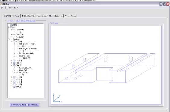
The application protocol implemented in this research work is based on STEP AP224 which contains explicit high-level part data in terms of feature attributes, tolerances, material specifications. It can be used to represent the information needed to define product data necessary for manufacturing product. The proposed system consists of the STEP-based feature modeler and intelligent process planning. The figure 3 gives an example of architecture to realize the process plan (the Holes analysis is represented as an example). The first step of the system uses STEP features as the basic elements for product representation and generates the graphical STEP AP224 based product representation. The product characteristics and the features parameters are represented in tree view and graphical format by the feature modeler. This modeler uses the specific algorithm to convert product information (STEP AP224) into a tree based representation format to be used as input for process planning. Figure 4 shows an example of feature based representation of product in the system.
This representation provides the part information to execute the following steps: micro process planning to determine the machining procedure for each
feature according to machining parameters and tools selection selection of suitable CNC machine
macro process planning to generate the process plans
generation of G-codes of process plans and simulation possibility
Figure 3 system architecture
Feature Parameter Knowledge of Tool accessibility for machining feature Product Features CNC Machine Data Hole Hole Diameter Hole Height Hole Bottom condition Hole Type Tool Selection Tool Type Tool Material Tool Angle Tool Length Tool Diameter Hole Position Hole Oriantation
Micro Process planing
Macro Process planing
Product Product Material Product Dimension Tools Data base Machine Selection Knowledge of Part accessibility vs. machine accessibility Knowledge of Tool accessibility for machining feature
Direction of tool for machining feature
Procedure of machining feature for
rough and finishing Feed rate and Spindle
speed Machining Time
Setup Time and Time of tool moving between each feature
Tool Cost Machine Cost Material Cost Material Data G-code Generation each suitable Process
Planning Optimum procedure for machining feature (Time ,Cost ,Tool life
,Quality, ...)
Machine Information
Optimum procedure for sequence of machining (Moving Time ,Setup ,...)
Setup face , Machining face Sequence of machining features Knowledge of Tool selection Knowledge of precedence operation ... Simulation Process Planning
Figure 4 product characteristics and features representation
3.1 micro process planning to determine the machining procedure for each
feature and parameters and tools selection
This step selects the machine tools on which the machining operations can be performed to produce the given feature. This step is implemented using a product information, tools data base, tools knowledge as input of the step. Figure 6 presents the user interface to edit the tool databases. Experts use this interface to complete the database according to available tool information. This step receives information for each feature in the part and generates the needed machining operations to realize the feature. The knowledge of tools accessibility for machining feature and tool databases are the main inputs of this step. The outputs of this step are: 1) the direction of tool for machining feature, 2) the procedure of machining feature for rough and finishing, 3) the feed rate and spindle speed, 4) the machining time, 5) the tool cost.
The tools selection is based upon machining feature and its associated machining operation. The output of this step contains recommended tools to be used to realize the feature. These recommended tools can be used as keys to search available tool databases to find the suitable tool.
3.2 selection of suitable CNC machine
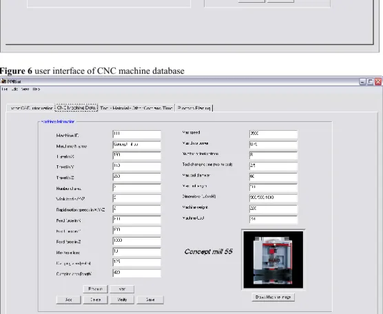
The CNC machine selection is realized by considering some constraints about feature orientation and feature position data of each feature which are provided from: 1) design file, 2) knowledge of tool direction accessibility for machining of each feature and 3) knowledge of accessibility of each type of CNC machine to part. According to these constraints and constraints related to part dimension, part weight vs. max table load of CNC machine, the suitable CNC machine is selected from the available CNC machines database. Figure 5 shows the user interface to manipulate the CNC machine database.
Figure 5 user interface of tool database
Figure 6 user interface of CNC machine database
3.3 macro process planning to generate the process plans
The process plan generation is a procedure to group the sequence of machining features into process plan. The operation sequence arranges the machining sequences in each generated process plan by considering the information about precedence machining
feature, setup face, machining face, setup time, time of tool moving between each feature and time of tool changing. In addition, the optimization algorithms are implemented to select the optimal process according to manufacturing process cost, setup time, tool changes time among the operations. The system contains a set of rules guiding the process planning selection for prismatic parts.
As shown in Figure 7, the alternative process plans are proposed for related part. Each alternative process plan indicates the selected CNC machine and the sequences of machining to be executed during setup. The machining features describe what the machine should do and the machining sequences describe how the features should be manufactured with related sequence tool. The cost presentation allows combination of several cost produced during process plan setup such as material, tools, CNC machine and labor cost to estimate final manufacturing cost. The tool and machine information are also provided to give the details of tools and machine used during machining sequences.
3.4 generation of G-codes of process plans and simulation possibility
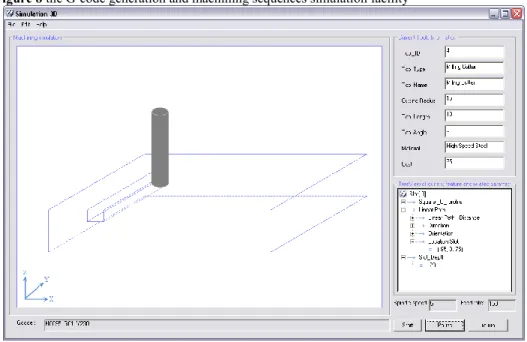
As shown in Figure 8, the specific facility is provided to generate a G-code of physical process plan. This step receives the information related to the part (features, material, etc.) and information produced by process planning (machining operations, tools, process sequences parameters, etc.) to generate a G-code file. Specific module is developed to use the provided information to simulate the machining sequences in the 3D format.
Figure 8 the G-code generation and machining sequences simulation facility
4 Conclusion
Intelligent manufacturing process selection improves the efficiency of manufacturing process. In PPRint tool, in the product design stage, the product model is based on the STEP application protocol, AP 224. A STEP-based feature modeler has been developed to browse the STEP file and to illustrate the product information in the feature tree view and in the graphical format. In process planning stage, an intelligent rule based process planning system has been developed to integrate the manufacturing process attributes, material parameters, and product specifications to satisfy design requirements.
The approach proposed, consists of different phases, such as identification of the pairs of feature/tool that satisfy the required conditions according to optimum procedure (example: the suitable depth of cut, spindle speed and feed rate that will be chosen during machining.), generation of the possible process plans from identified tools/Machine pairs, and selection of the most interesting process plans considering the economical or timing indicators (Example: cost of material, cost of machine, cost of tool, setup time, machining time, tool change time). The suitable manufacturing processes plans are selected according to the acceptable range of quality, time and cost factors. Each process plan is represented in the tree view format by the information items corresponding to their CNC Machine, required tools characteristics (characteristic, cost), times (machining, setup, preparatory) and the required machining sequences. The process simulation module is provided to demonstrate the different sequences of machining to realize the final piece. After selection of suitable machining sequences, the G-code language used by CNC machines is generated automatically.
In PPRint, the AP224-STEP (machining feature) is used as input, in other words according to feature based design this format is provided to process planning, but it's not possible to force designer to design in feature base procedure. In this situation feature extraction is inevitable to capture features parameters for process planning.
References
1 Zdrahal Z., Valasek M. and Cermak J. (1999) ‘Selecting Manufacturing Technology: A Knowledge Modelling Approach’, Journal of Intelligent and Robotic Systems, vol. 26, p. 405-422.
2 Lee G., Eastman C. M. and Sacks R. (2007) ‘Eliciting information for product modeling using process modeling’, Data & Knowledge Engineering Vol.62, pp.292–307
3 Tichkiewitch S. and Véron M. (1998) ‘Integration of Manufacturing Processes in Design’, CIRP Annals - Manufacturing Technology, Volume 47, Issue 1, Pages 99-102
4 Esawi A. M. K. and Ashby M. F. (1998) ‘Cost-based ranking for manufacturing process selection’, in Integrated Design and Manufacturing in Mechanical Engineering ‘98, Proceedings of the 2 nd IDMME Conference held in Compiegne, France
5 Ashby M.F., Brechet Y.J.M and Cebond D. (2004) ‘Selection strategies for materials and processes’, Materials and Design, Vol. 25, pp. 51-67
6 Lovatt A.M., Shercliff H.R. (1998) ‘Manufacturing process selection in engineering design’, Materials and Design, Vol. 19, pp. 205-230
7 Zha X.F (2005) ‘A web-based advisory system for process and material selection in concurrent product design for a manufacturing environment’, International Journal of Advanced Manufacturing Technology, Vol. 25, pp. 233-243
8 Gupta M. and Galloway K. (2003) ‘Activity based costing and management and its implications on operations management’, Technovation, Vol. 23, n°3, pp. 131-138
9 Ishii K., Lee C.H. and Miller R.A. (1990) ‘Methods for process selection in design’, Proceedings of the ASME Design Theory and Methodology Conference, vol. 27, pp. 105-112
10 Ishii K., Krizan S., Lee C.H. and Miller R.A. (1991) ‘HyperQ/Process - An Expert System for Manufacturing Process Selection’, Proceedings of the 6th Int Conf on AI applications in Engineering, pp. 405-422
11 Boothroyd G., DewhurstE P. and Knight W. (1994) ‘Production Design for Manufacture and Assembly’, edited by Marcel Dekker Inc., ISBN 0-8247-9176-2
12 Devireddy CR, Ghosh K (1999) Feature-based modeling and neural networks-based CAPP for integrated manufacturing. Int J Comput Integ Manuf 12:61–74
13 Khoshnevis B, Sormaz DN, Park JY (1999) An integrated process planning system using feature reasoning and space search-based optimization. IIE Trans 31:597–616
14 Berger U. and Kretzschmann R. (2009) ‘A Heuristic STEP-NC Based Process Planning Tool for Sequencing NC Machining Operations’, Advanced Design and Manufacturing Based on STEP, Springer Series in Advanced Manufacturing, Publisher: Springer London, pp.49-78 15 L. T. Ly, S. Rinderle and P. Dadam (2008) ‘Integration and verification of semantic
constraints in adaptive process management systems, Data & Knowledge Engineering, Vol.64 pp.3–23
16 Thibault A., Siadat A., Bigot R. and Martin P. (2007) ‘Proposal for Product Process Integration using Classification and Rules’, International IEEE conference on Computer as a tool, Warsaw (Poland)
17 Sadeghi M., Noel F. and Hadj-hamou (2007) ‘Toward a framework for effective collaborative product development’, in the The Future of Product Development Book (Proceedings of the 17th CIRP Design Conference) published by Springer, pp. 279-289