Dynamic stress prediction in catenary wires for fatigue analysis
Texte intégral
Figure


Documents relatifs
Nous montrons ensuite la problématique du transfert du maximum de puissance enschématisant le plus possible une chaîne de conversion élémentaire composée d’un
Loïc Francon, Thierry Ameglio, Erwan Roussel, Irène Till Bottraud, Guillaume Charrier, Christophe CoronaB. To cite
Indeed, contact wire failure which occurred inline (next to a claw) are different from those obtained using the test bench of RTRI.. In both cases, the fatigue
Sommes-nous juste aveuglés Pour ne pas voir les dégâts De l’obsolescence programmée, De la pub et des médias.. Sommes-nous juste inconscients Pour continuer de reporter, Pour
[r]
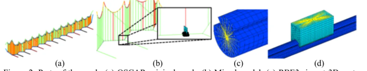
In section 3, the proposed models are used to analyze the influence of damping on catenary vibrations using a simple pretensioned wire, an impact test on a full model and a
Since a solid line is a singular case of dashing, the method is valid for rendering thick solid antialiased polylines with correct caps and joins without the need to tessellate
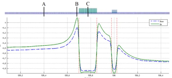
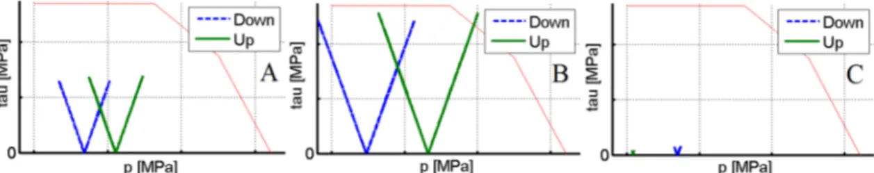
Based on experimental measurements performed along an electrified railway line, this paper examines different assumptions which may make possible new applications
