HAL Id: hal-01401350
https://hal.archives-ouvertes.fr/hal-01401350
Submitted on 23 Nov 2016
HAL is a multi-disciplinary open access
archive for the deposit and dissemination of
sci-entific research documents, whether they are
pub-lished or not. The documents may come from
teaching and research institutions in France or
abroad, or from public or private research centers.
L’archive ouverte pluridisciplinaire HAL, est
destinée au dépôt et à la diffusion de documents
scientifiques de niveau recherche, publiés ou non,
émanant des établissements d’enseignement et de
recherche français ou étrangers, des laboratoires
publics ou privés.
70km external cavity DWDM sources based on O-band
Self Seeded RSOAs for transmissions at 2.5Gbit/s
Gaël Simon, Fabienne Saliou, Philippe Chanclou, Qian Deniel, Didier Erasme,
Romain Brenot
To cite this version:
Gaël Simon, Fabienne Saliou, Philippe Chanclou, Qian Deniel, Didier Erasme, et al..
70km
external cavity DWDM sources based on O-band Self Seeded RSOAs for transmissions at
2.5Gbit/s.
Optical Fiber Communications conference, Mar 2014, San Francisco, United States.
�10.1364/OFC.2014.W3G.5�. �hal-01401350�
70km external cavity DWDM sources based on O-band Self
Seeded RSOAs for transmissions at 2.5Gbit/s
Gaël Simon(1-2), Fabienne Saliou(1), Philippe Chanclou(1), Qian Deniel(1-2), Didier Erasme(2), Romain Brenot(3)
(1) Orange Labs- 2, avenue Pierre Marzin, 22307, Lannion, France, gael.simon@orange.com (2) Telecom ParisTech- 46 rue Barrault F-75634 Paris Cedex 13
(3) III-V Labs- Route de Nozay F-91461 Marcoussis Cedex
Abstract: A DWDM self-seeded source achieves transmission in the O-band up to 90km SSMF at
2.5Gbps. Moreover, a “face-to-face” self-seeded architecture permits to realize transmissions at 2.5Gbps with extra-long optical cavities reaching 70km of SSMF.
OCIS codes: (060. 4510) Optical communications; (250.5980) Semiconductor optical amplifiers;
1. Introduction
Dense Wavelength Division Multiplexing (WDM) is facing high technical and economical challenges to be implemented in the optical access networks. Its topological architecture need to remains simple, using cyclic multiplexers and de-multiplexers with the objective to share a maximum of fiber resources in the network. Its cost need to be maintained low as many terminations are to be considered for access networks such as mobile front-haul or business services networks [1]. There, colorless transmitters come as an evidence to reduce production costs and avoid a large amount of sparing items in the network. Among several existing colorless technologies, self seeded DWDM sources based on RSOAs have shown a certain appeal with the advantage to provide an automatic and passive establishment of the wavelength [2]. It brings simplicity to use DWDM in the access networks fields with operational savings realized and external controllers to adjust the wavelength avoided.
Transmissions performances of those sources were shown to be mainly limited by the chromatic dispersion of the fiber, therefore, for the first time to our knowledge, we propose in this paper to experiment a self seeded DWDM architecture with RSOAs in the O-band. Firstly, by means of a simple and shared mirror after the multiplexer to close the external cavity, a regular self seeded architecture is presented to point out its performances at 2.5Gbit/s. Then, contra-data cancellation is optimized [3], using a RSOA in saturation regime in a new architecture where the mirroring function is moved to the network termination [4].
2. “Regular” self-seeded architectures performances
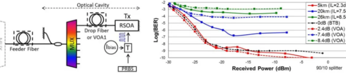
Figure 1 depicts the experimental setup of a transmission with an O-band RSOA exhibiting a high polarization dependent 1330nm gain equal to 25dB for small signal input optical power (for 100mA bias current). A 4 channels flattop AWG with 3dB of insertion losses is used with a channel spacing and a 3dB bandwidth of 280GHz and 200GHz respectively. The experiment was performed on the channel centered at 1325nm. The common port of this multiplexer is connected to a 90%/10% splitter followed by a reflective mirror on the low loss arm of the splitter. This results in an optical cavity, which concentrates the amplifier emission in the very narrow band within the chosen AWG channel. This operation provides a colorless optical source called “self-seeded”.
The Standard Single Mode drop Fiber (SSMF) between the RSOA and the AWG leads to a long external cavity acting as the transmission system’s optical source. For experimental purposes, the drop fiber may be replaced by a Variable Optical Attenuator VOA1. The reception system consists in a VOA (VOA2) followed by an APD and a BER tester (BERT). At the output of the AWG, a feeder fiber will be inserted to estimate the maximum transmission reach of our experiments. The RSOA, biased with a 100mA current, is directly modulated by a 2.5Gbps non-return to zero, 231-1 pseudo-random bit sequence from a pulse pattern generator with a 3.8V peak to peak electrical signal.
Fig. 1: Experimental setup of the “regular” self-seeded Fig. 2: BER transmission performances versus received power at 2.5Gbps, for standart self-seeded with different cavity length and their
Fig 2 presents the measured BER, when varying the drop fiber length or the attenuation of VOA1, inside the cavity and comparing equivalent attenuations (curves of the same color). No feeder fiber is added. Polarization controllers are required in order to tune the polarization into the high gain axis of both RSOA simultaneously (O-band Faraday mirror were not available for our experiment [4]).
BER below 10-3 (compatible with error-free transmission when a FEC is used) can be obtained for cavity length as long as 26km corresponding to a total insertion loss in the cavity of 13.9dB divided in 8,5dB for the SMF and 5.4dB for the AWG and the partial mirror. Since the drop fiber consists in a SSMF whose dispersion is null around 1300nm, there should be no degradation when using such a fiber as compared to the equivalent attenuation as can be observed in fig G when comparing the experiment with a fiber and with the VOA1 set at an equal attenuation. We believe that the case of the blue curve showing a degraded VOA1 measurement may be due to a bad polarization tuning.
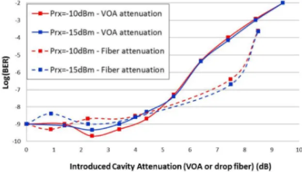
In addition, some more BER versus received power measurement were performed in the same conditions. They led to “BER versus cavity attenuation” curve (drop fiber or VOA1 attenuation) for a given APD received power. These results, presented in figure 3, show that the optimum performance does not require necessarily minimizing cavity internal losses, those being compensated by the RSOA gain. When the attenuation in the cavity becomes too high, BER impairment appears. This effect has been observed before and corresponds to the situation where the RSOA gain stop compensating internal loss and cavity resonance is lost.
To enhance the DWDM sources transmission performances, a tradeoff needs to be found between its reached output power and its cavity losses. Indeed, both the drop fiber and the splitter realizing the mirror participate to the internal loss of the cavity [2]. Matching the splitting ratio to the drop fiber length can achieve an optimization process.
Fig. 3: Comparison of the BER transmission performances versus introduced cavity attenuation for a given received power at 2.5Gbps
Fig. 4: 2.5Gbps BER transmission performances versus received power, for 10m cavity (blue), 10km cavity (red/orange) and 26km
cavity (green) for various feeder fiber length
Figure 4 presents BER curves versus received power using the previous optimization. Several designs are analyzed varying splitting ratio, drop fiber length and transmission fiber length. Error free transmissions when a Forward Error Correction (FEC) is used (BER<10-3) can be obtained for various structures such as:
• a cavity of a few meters using a 50/50 splitter and a 90km transmission fiber (equivalent to a 32dB optical budget) , reaching BER lower than 10-5
• a 26km self-seeded cavity, followed by 40km transmission fiber using a 90%/10% splitter allowing a BER of 3.5x10⁻⁴ for a received power of -22.3dBm
The “regular” self-seeded solution in O-band has proved its interest, record breaking long cavities up to 26 km. Nevertheless, this architecture may cause operational issues: the presence of a mirror between the two AWG does not allow flexibility in case of a multiple PON technologies convergence. Moreover, it has been shown that the optical cavity was saturated if the signal coming back to the RSOA was high enough. In that way, data compression has been optimized, using RSOA saturation in a new architecture where the mirroring function is moved to the network termination as described in the following part.
3. RSOAs “face-to-face” self-seeded architecture performances
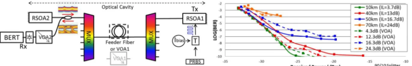
This second experimental setup is shown on figure 5. The NRZ modulated O-band RSOA, called RSOA1, is the same as in the previous experimental setup and is directly connected to the same O-band flattop AWG. A SSMF “feeder fiber” having lengths up to 70km which may be replaced for experimental purpose by a VOA (VOA1), connects the common port of the AWG to the common port of a second identical AWG. The second AWG is followed by a 90/10 splitter. The major part of the optical power is launched into a second RSOA called RSOA2,
similar to RSOA1, which is not modulated and only provides amplification and reflection of the light into the cavity. In addition, the RSOA2 in saturation regime permits to erase the data from the optical signal and to return a clean carrier [5]. Thus, the two “face-to-face” RSOAs create an optical cavity able to concentrate optical power on the multiplexer channel. A first VOA (VOA1) was inserted between the two multiplexers to estimate maximum internal losses inside the cavity. The other arm of the splitter is chosen to be the output of the DWDM source and is connected to a VOA (VOA2), followed by the APD–CDR block (Clock and Data Recovery) for BER measurements.
The RSOA1 current has been chosen through optimizing the extinction ratio of the signal reaching the APD, and was finally set to 100mA. RSOA2 current was set to 200mA, verifying that the data coming out from RSOA2 were erased (Fig. 5) and that the signal was powerful enough to reach RSOA1, in order to create a retroaction in the cavity.
Fig 5: Experimental setup of the RSOAs “face–to-face” self-seeded Fig. 6: BER transmission performances versus received power at 2.5Gbps, for RSOAs “face-to-face” self-seeded with different cavity length and their equivalent attenuation using VOA (dashed)
Figure 6 shows the measured BER versus the optical power received by the APD for different fiber length, and their equivalent VOA1 attenuation. As expected at zero-dispersion wavelength, introduction of a certain length of fiber make the optical source behaves as if only an equivalent attenuation were introduced. For cavities shorter than 40km (red and green curves), an error free BER, lower than 10-10, is measured at the receiver when VOA2 is set to 0dB. Finally, considering FEC applied afterwards, an error free transmission is reachable with a BER of 1.3x10⁻⁴ at -27.3dBm of received power with a 70km cavity (orange). To the best of our knowledge this represents the longest external cavity DWDM source capable to carry out information at 2.5Gbit/s.
4. Conclusion
We successfully created an external cavity source based on an O-band RSOA self-seeded solution. An optimization of the cavity insertion losses permitted to extend the optical budget to reach a 90km transmission at 2.5Gbps with a few meter of drop fiber. We demonstrated for the first time to the best of our knowledge, that a 26km long seeded cavity was possible in addition with a 40km feeder fiber. These results led us to design another type of self-seeded solution, which uses two “face-to-face” RSOAs. One of these is strongly saturated and the other one used directly modulated. The proposed architecture permits a 70km long optical cavity (140km round trip), having the first advantage to be colorless in self-according its emitted wavelength on the AWG channel, and the second advantage to not require any components other than fiber between the two multiplexers of the WDM PON system.
5. Acknowledgements
This research activities was supported by the European Union's Seventh Framework Program (FP7/2007-2013) under grant agreement ERMES n° 288542 2012 and from the French National Research project LAMPION registered under N° ANR-13-INFR-0002- by the European FP7 project ERMES and National project LAMPION.
6. References
[1] P. Chanclou et al, « Optical Fiber Solution for Mobile Fronthaul to Achieve Cloud Radio Access Network Philippe Chanclou, Orange Labs, France”, Future Network & Mobile Summit 2013, 3 - 5 July 2013, Lisbon, Portugal
[2] Q. Deniel, F. Saliou, P. Chanclou, D. Erasme, “Self-Seeded RSOA based WDM-PON Transmission Capacities,” in Proceedings of OFC 2013, OFC/NFOEC 2013, Anaheim, CA, USA, paper OW4D.3.
[3] Ó Dúill, S. et al. 2012 “Efficient modulation cancellation using reflective SOAs”, Optics Express, OSA, USA, vol. 20, iss. 26, pp. B587-B594
[4] M. Presi, A. Chiuchiarelli, R. Corsini, E. Ciaramella, “Uncooled and polarization independent operation of self-seeded Fabry-Perot lasers for WDM-PONs”, IEEE Photonics Technology Letters, vol. 24, no.17, pp. 1523, 2012.
[5] Q. Deniel et al, “Amplified RSOA Self-Tuning Laser for WDM PON Using Saturated SOA for Noise Reduction and Data Cancellation”, ECOC 2013, paper We.1.F.5