HAL Id: hal-02399485
https://hal.archives-ouvertes.fr/hal-02399485
Submitted on 9 Dec 2019
HAL is a multi-disciplinary open access
archive for the deposit and dissemination of sci-entific research documents, whether they are pub-lished or not. The documents may come from teaching and research institutions in France or abroad, or from public or private research centers.
L’archive ouverte pluridisciplinaire HAL, est destinée au dépôt et à la diffusion de documents scientifiques de niveau recherche, publiés ou non, émanant des établissements d’enseignement et de recherche français ou étrangers, des laboratoires publics ou privés.
A compact lens-primary source structure for avoidance
radar system
François Gallée, Gabrielle Landrac, Michel Ney
To cite this version:
François GallÉe, Gabrielle Landrac, Michel Ney. A compact lens-primary source structure for avoid-ance radar system. EuMC 2001 : 31st European Microwave Conference, Sep 2001, Londre, United Kingdom. pp.1 - 4, �10.1109/EUMA.2001.339110�. �hal-02399485�
A COMPACT LENS-PRIMARY SOURCE STRUCTURE FOR
AVOIDANCE RADAR SYSTEM
F. GALLEE, G. LANDRAC, M.M. NEY
Laboratory for Electronics and Systems of Telecommunications (LEST) Ecole Nationale Supérieure de Télécommunications de Bretagne-University of BrestBP 832 , 29285 BREST Cedex, France
Phone:+33 2 29 00 13 48, FAX: +33 2 29 00 13 43 [email protected]
Abstract
The design and realisation of a compact structure that includes an artificial lens and a primary source in planar technology is presented. Such structure is the RF part of a monopulse radar system to detect obstacles in front of a vehicle. First, the feasibility of such compact structure is implemented at 32 GHz for which the lens is built using a stack of parallel-plate waveguides using foam technology (low-loss dielectric material with relative permittivity close to one). Extension to 76 GHz requires the primary source feeding to use branch coupler technique and the radiating element in membrane technology. Alternate original structures are implemented at 32 GHz tested and compared with the model. Results show that the proposed structure meets the requirements and that models used for the design are generally in good agreement with measurements.
Introduction
With the recent availability of millimetre-wave frequency bandwidths for civil applications, much effort has been devoted to the development of new technologies for low-cost mass production. For instance, the frequency range from 76 to 77 GHz was allocated for avoidance radar systems that should be embarked on future automobile generation. Third generation systems should be able to detect a motorcycle moving with a velocity of 130 Km/h on any of a three-lane highway within a distance of 120 m. Other requirements associated with the emitted power are: antenna gain from 25dB minimum to 40 dB maximum with scanning angle of ±15°, linear polarisation and 30 dB isolation between reception and transmission channels. Considering the minimum required gain and the need of compactness, the use of arrays is excluded because of the large number of elements that one would need. A focusing system with a wide scanning angle seems to be the most appropriate. In addition, the use of a dielectric lens is not compatible for a low-cost mass production. This is due to the fact that wide scanning angle would require, a profile on both faces of the lens and a low-loss dielectric at 76 GHz which is not available at low-cost. A large scanning angle reflector with planar primary source and realised with metal painted foam was shown as a potential solution. [1].In this paper, new results pertaining to a structure using an artificial lens [2] is presented. Such a lens is made of stacked parallel-plate waveguides whose height (distance between conducting plates) allows one to adjust the equivalent index of the lens (see figure 1). This brings an additional degree of freedom as compared to dielectric lenses. Bifocal lenses optimised for 10°-scanning angle are the best suited for the application described above. Finally, two types of feeding network implemented at 32 GHz are realised and tested.
Primary source
The analytical approach used in the paper uses the array theory applied to radiating apertures [3]. The magnitude and phase of aperture sources are determined by the optical length from the primary source weighted by the radiation pattern of the later. Note that the lens is in the primary source far-field region. Concerning the primary source, several solutions can be considered:
• Pyramidal horn which are not well adapted to low-cost condition, yet the most practical for measurements at 76 GHz as standard transition can be used for connection to the network analyser. The feasibility of using a metal-painted foam horn was established. Additional loss of 0.3 dB only as compared to commercial horn.
• Printed elements in microstrip technology on Duroïd substrate which was found a suitable solution up to 32 GHz. However, the efficiency drops substantially at 76GHz.
• Printed elements using membrane technology [4] is the alternate approach in terms of cost and performances
Artificial lens with horn as primary source was designed and tested at 76 GHz [2]. Some problem concerning bandwidth is anticipated in using printed planar feeding circuits at this frequency. Preliminary tests at 32 GHz are first carried on.
Monopulse system feeding
For determining the radiation pattern of the printed elements, the approximated approach described in [5] can be applied. To validate it, comparison with a full-wave computation in the case of a 4x2 patch array (0,6λ0
distance between elements), was performed. Errors less than 1dB for aperture angles up to 60° in the plane with 45° tilt from both E et H planes. This allows a fast computation of the radiation characteristic of the whole antenna system. Finally, the required high angular resolution (0,7°) would necessitate a difficult and costly system base on beam scanning by element switching technique. A monopulse system, that uses the information from a "sum" and "difference" channel amplitude detected form the radar, is better suited in this case. Different structures were investigated. For instance, hybrid ring and branch coupler (figure 2) solutions for the feeding circuits were compared. Their S-parameters are given figure 3.
Results and discussion
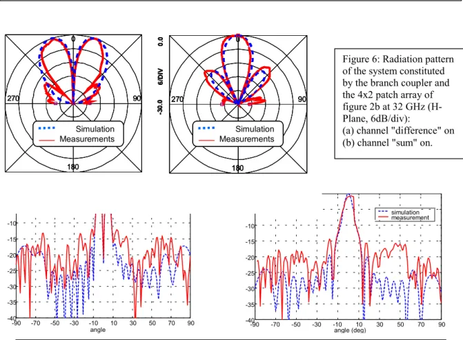
First, the patch array of figure 2a was built and the radiation pattern computed with a full-wave model and measured. The Figure 4 shows the radiation diagrams for both channels configurations. One can observe for the "difference" a zero radiation in the normal direction with level close to -30dB. Then, the whole system with the lens was again computed and measured. This time the model explained above was used. Figure 5 shows the quite good correspondence between the theory and the experiment, except that side lobe level predicted by the model are slightly lower. Also note the substantial increase of the gain (and the corresponding decrease of the aperture angle) when the artificial lens is included (see figure 5). As shown in figure 3, compared to the branch feeding circuit configuration (figure 2b), the hybrid ring approach yielded a better bandwidth at 32 GHz. However, it cannot be considered for extension to 76 GHz because the distance between patches (made maximum by using membrane technology) becomes so small that it precludes the line "sum" to run in between elements (see figure 2a). One approach consists in using multi-layered technology but at the price of complexity and, thus, higher cost. The approach using the branch coupler (figure 2b) is a solution that yields a layout which does not produce the problem mentioned above. However, the design of such a device with a branch coupler is more difficult because of its rather small bandwidth and of the losses associated with the quarter-wavelength line introduced on one port (that breaks the symmetry of the structure) : all this explains the lower level of one of the main lobes in the “difference” channel. It should be noted that the branch coupler and access lines were realised in TFMS (Thin Film MicroStrip). Building the quarter wavelength line in membrane technology (having less loss than TFMS) or cascading two branch couplers may improve the radiation pattern.
Conclusion
A complete antenna structure including a focusing system, the primary source and its RF feeding circuit was investigated. Alternate circuits for primary source feeding were compared and tested at 32 GHz. Hybrid ring solution was found to provide the largest bandwidth. However, its application to 76 GHz is technically compromised if one wants to keep the low-cost single layer option. Compactness for the whole monopulse radar system was achieved at 32 GHz by including a bifocal lens in foam technology. Results show that the structure meets the requirement for avoidance radar system as the lens only was tested with satisfactory performances at 76 GHz [2]. In the same time, a simplified model based on ray and array theory was validated by the measurements. Finally, alternate solutions using the branch coupler to separate channels of the monopulse radar are on investigation to obtain a sufficiently wide bandwidth at 76 GHz.
References
[1] F. SCHAEFER ,F. GALLEE, G. LANDRAC and M. NEY, "Optimum reflector shapes for anti-collision radar at 76 GHz", Microwave and Optical Technology Letter ,March 2000
[2] F. GALLÉE, G. LANDRAC and M. NEY Low-cost artificial lens for compact monopulse antenna detector at 76 GHz, AP-Millenium Conference, Davos, April 2000.
[3] J.C. SLETTEN "Reflector and lens antenna analysis and design using PC's", ARTECH HOUSE 1991 [4] S. PERROT and Ch. PERSON, H. LATTARD and M. NEY, " Proposed design solutions for low-cost
flip-chip membrane devices for millimeter-wave applications ", IEEE MTT-S Digest,1999, p.1905-1908.
[5] P. VAUDON, B. JECKO, P. BRACHAT, "Some relations between the radiation patterns in the two main planes and the whole radiation pattern", Ann. Télécommunications; 51, n° 5-6, 1996, pp 227-232
0. 0 vo ies c o u p lé e s -1 0 .0 0. 0 ad ap ta ti o n et v o ie is o lée -5 0 .0 40.0 GHz freq 20.0 GHz S 11 S 13 S 12 S 14 R etu rn lo ss an d i sol at ed p o rt C oup le d p o rt s
Hybrid ring: S-parameters
0.0 -1 0 .0 0.0 ad ap ta ti o n et v o ie is o lé e -5 0 .0 40.0 GHz freq 20.0 GHz V o ie co u p lé es S11 S31 S21 S41 R etu rn lo ss an d i sol at ed p o rt C oup le d p o rt s
Branch coupler: S-parameters
18 0. 0 ph a se -1 8 0. 0 40.0 GHz freq 20.0 GHz Voie 1 (différence) Voie 3 (somme) Port 1 (difference) Port 3 (sum) Hybrid ring: Phase difference between the coupled ports 18 0 .0 pha s e -180. 0 40.0 GHz freq 20.0 GHz Voie 3 (différence) Voie 1 (somme) Port 1 (difference) Port 3 (sum) Branch coupler: Phase difference between the coupled ports 3 λ 3 λ 3 λ 3 λg/4 λλλλg/4 λλλλg/4 λλλλg/4 1 4 3 2 λλλλg / 4 1 3 2 4 0. 0 vo ies c o u p lé e s -1 0 .0 0. 0 ad ap ta ti o n et v o ie is o lée -5 0 .0 40.0 GHz freq 20.0 GHz S 11 S 13 S 12 S 14 R etu rn lo ss an d i sol at ed p o rt C oup le d p o rt s
Hybrid ring: S-parameters
0.0 -1 0 .0 0.0 ad ap ta ti o n et v o ie is o lé e -5 0 .0 40.0 GHz freq 20.0 GHz V o ie co u p lé es S11 S31 S21 S41 R etu rn lo ss an d i sol at ed p o rt C oup le d p o rt s
Branch coupler: S-parameters
18 0. 0 ph a se -1 8 0. 0 40.0 GHz freq 20.0 GHz Voie 1 (différence) Voie 3 (somme) Port 1 (difference) Port 3 (sum) Hybrid ring: Phase difference between the coupled ports 18 0 .0 pha s e -180. 0 40.0 GHz freq 20.0 GHz Voie 3 (différence) Voie 1 (somme) Port 1 (difference) Port 3 (sum) Branch coupler: Phase difference between the coupled ports 0. 0 vo ies c o u p lé e s -1 0 .0 0. 0 ad ap ta ti o n et v o ie is o lée -5 0 .0 40.0 GHz freq 20.0 GHz S 11 S 13 S 12 S 14 R etu rn lo ss an d i sol at ed p o rt C oup le d p o rt s
Hybrid ring: S-parameters
0. 0 vo ies c o u p lé e s -1 0 .0 0. 0 ad ap ta ti o n et v o ie is o lée -5 0 .0 40.0 GHz freq 20.0 GHz S 11 S 13 S 12 S 14 R etu rn lo ss an d i sol at ed p o rt C oup le d p o rt s
Hybrid ring: S-parameters
0.0 -1 0 .0 0.0 ad ap ta ti o n et v o ie is o lé e -5 0 .0 40.0 GHz freq 20.0 GHz V o ie co u p lé es S11 S31 S21 S41 R etu rn lo ss an d i sol at ed p o rt C oup le d p o rt s
Branch coupler: S-parameters 0.0
-1 0 .0 0.0 ad ap ta ti o n et v o ie is o lé e -5 0 .0 40.0 GHz freq 20.0 GHz V o ie co u p lé es S11 S31 S21 S41 R etu rn lo ss an d i sol at ed p o rt C oup le d p o rt s
Branch coupler: S-parameters
18 0. 0 ph a se -1 8 0. 0 40.0 GHz freq 20.0 GHz Voie 1 (différence) Voie 3 (somme) Port 1 (difference) Port 3 (sum) Hybrid ring: Phase difference between the coupled ports 18 0. 0 ph a se -1 8 0. 0 40.0 GHz freq 20.0 GHz Voie 1 (différence) Voie 3 (somme) Port 1 (difference) Port 3 (sum) 18 0. 0 ph a se -1 8 0. 0 40.0 GHz freq 20.0 GHz Voie 1 (différence) Voie 3 (somme) Port 1 (difference) Port 3 (sum) Hybrid ring: Phase difference between the coupled ports 18 0 .0 pha s e -180. 0 40.0 GHz freq 20.0 GHz Voie 3 (différence) Voie 1 (somme) Port 1 (difference) Port 3 (sum) Branch coupler: Phase difference between the coupled ports 18 0 .0 pha s e -180. 0 40.0 GHz freq 20.0 GHz Voie 3 (différence) Voie 1 (somme) Port 1 (difference) Port 3 (sum) Branch coupler: Phase difference between the coupled ports 3 λ 3 λ 3 λ 3 λg/4 λλλλg/4 λλλλg/4 λλλλg/4 1 4 3 2 λλλλg / 4 1 3 2 4
Foam
block
Feeding
circuit
Artificial lense
Parallel plates
Primary
source
array
Figure 1: Antenna structure Figure 2: Patch array with feeding circuit for monopulse radar system: a) hybrid ring configuration b) branch coupler configuration
(a)
(b)
Figure 7: Radiation pattern of the 4x2 patch array of figure 2b (branch coupler) at 32 GHz with a bifocal lens of the type illustrated in figure 1 (constant refractive index):
(a) channel "difference" on (b) channel "sum" on.
-90 -70 -50 -30 -10 10 30 50 70 90 -40 -35 -30 -25 -20 -15 -10 -5 0 angle (deg) dB simulation measurement -90 -70 -50 -30 -10 10 30 50 70 90 -40 -35 -30 -25 -20 -15 -10 -5 0 angle dB simulation measureme
Figure 4: Radiation pattern of the system constituted by the hybrid ring and the 4x2 patch array of figure 2b at 32 GHz (H-Plane, 6dB/div):
(a) channel “difference" on (b) channel "sum" on. 0 90 180 270 MeasurementSimulation
0 90 180 270 Measurement Simulation
-90 -70 -50 -30 -10 10 30 50 70 90 -40 -35 -30 -25 -20 -15 -10 -5 0 angle (deg) dB simulation mesure simulation measurement -90 -70 -50 -30 -10 10 30 50 70 90 -40 -35 -30 -25 -20 -15 -10 -5 0 s imulation me s ure simulation measurement -90 -70 -50 -30 -10 10 30 50 70 90 -40 -35 -30 -25 -20 -15 -10 -5 0 s imulation me s ure simulation measurement
Figure 5 : Radiation pattern of the 4x2 patch array with the hybrid ring of figure 2a (hybrid ring) at 32GHz with a bifocal lens of the type illustrated in figure 1 (constant refractive index): (a) channel “difference” on (b) channel “sum” on.
0 90 180 270 0. 0 6/ D IV -3 0 .0 Simulation HP Momemtum Mesure Simulation Measurements 0 90 180 270 0. 0 6/ D IV -3 0. 0 Simulation HP Momemtum Mesure Simulation Measurements 0 90 180 270 0. 0 6/ D IV -3 0 .0 Simulation HP Momemtum Mesure Simulation Measurements 0 90 180 270 0. 0 6/ D IV -3 0 .0 Simulation HP Momemtum Mesure Simulation Measurements Simulation Measurements 0 90 180 270 0. 0 6/ D IV -3 0. 0 Simulation HP Momemtum Mesure Simulation Measurements 0 90 180 270 0. 0 6/ D IV -3 0. 0 Simulation HP Momemtum Mesure Simulation Measurements Simulation Measurements
Figure 6: Radiation pattern of the system constituted by the branch coupler and the 4x2 patch array of figure 2b at 32 GHz (H-Plane, 6dB/div):
(a) channel "difference" on (b) channel "sum" on.