HAL Id: hal-00972276
https://hal.archives-ouvertes.fr/hal-00972276
Submitted on 4 Apr 2014
HAL is a multi-disciplinary open access
archive for the deposit and dissemination of
sci-entific research documents, whether they are
pub-lished or not. The documents may come from
teaching and research institutions in France or
abroad, or from public or private research centers.
L’archive ouverte pluridisciplinaire HAL, est
destinée au dépôt et à la diffusion de documents
scientifiques de niveau recherche, publiés ou non,
émanant des établissements d’enseignement et de
recherche français ou étrangers, des laboratoires
publics ou privés.
microscale components for micro-optical benches
Cédric Clévy, Ion Lungu, Kanty Rabenorosoa, Philippe Lutz
To cite this version:
Cédric Clévy, Ion Lungu, Kanty Rabenorosoa, Philippe Lutz. Positioning accuracy characterization of
assembled microscale components for micro-optical benches. Assembly Automation, Emerald, 2014,
34, pp.69-77. �hal-00972276�
Assembled Microscale Components for
Micro-Optical Benches
Cédric Clévy, Ion Lungu, Kanty Rabenorosoa and Philippe Lutz Automation and Micro-Mechatronics Systems Department, FEMTO-ST Institute,
UMR CNRS 6174,ENSMM, Université de Franche-Comté, 25000 Besançon, France;
[email protected]
Structured Abstract:
This paper deals with the measurement of microscale components’ positioning accuracies used in the assembly of Micro-Optical Benches (MOB). The concept of MOB is presented to explain how to build optical MEMS based on out-of-plane micro-assembly of microcomponents. The micro-assembly platform is then presented and used to successfully assemble MOB. This micro-assembly platform includes a laser sensor that enables the measure of the microcomponent’s position after its assembly. The measurement set-up and procedure is displayed and applied on several micro-assembly sets. The measurement system provides results with a maximum deviation less than +/- 0.005°. Based on this measurement system and micro-assembly procedure, the article shows that it is possible to obtain a positioning errors down to 0.009°. These results clearly state that micro-assembly is a possible way to manufacture complex, heterogeneous and 3D optical MEMS with very good optical performances.
Keywords: Micro-Assembly, robotic assembly, positioning accuracy, characterization, Micro-Optical Bench, Microsystem assembly, MOEMS assembly
Article Classification: Research paper
Introduction
The necessity to build and manufacture smaller, more complex and smarter systems strongly pushes fields such as microfabrication and packaging. The next generation of integrated microsystems technologies with increased functionalities is notably focussing on extending to the 3rd dimension. The main drivers to achieve full 3D integration are the miniaturization, the integration of different technologies in a small factor and the increase of performances [Tolfree and Jackson 2006]. Several strategies may be used; the main one today relies on the wafer scale integration which takes advantages of microsystem fabrication. This alternative also faces difficulties as it is mainly applicable to large series of products and is strongly limited in terms of materials integration. Another promising way consists in using robotized micro-assembly means to perform the 3D integration at the chip level. This alternative is possible and is mainly oriented to smaller series of products but with high added value, enabling the combination of materials that are usually not compatible at the microfabrication level [Gauthier and Régnier 2010].
Many microscale products could be assembled using robotic micro-assembly but the MOEMS field is one of the most interesting and promising potential applications. Indeed, MOEMS can be comprising of several basic blocks (mainly optical components, compliant structures, sensors and actuators) resulting from many different microfabrication processes. Their monolithic integration is possible but requires complex design and fabrication both including trade-offs which may strongly decrease the performances of the system itself. Despite this high complexity, the potential applications are wide in fields such as biology, medicine, signal treatment and near field sensing
[Aljasem et al. 2011] [Sun and Xie 2011] [Aljasem et al. 2008]
Robotic micro-assembly recently shows important developments: many microgrippers, actuation principles and sensors have been proposed. Many studies have also been carried out to investigate the microscale specificities such as surface force influence, signal observation, control schemes considering vibrations or high signal to noise ratios [Clévy et al. 2011] [Chaillet and Régnier 2010] [Agnus et al. 2013] [Rabenorosoa et al. 2009-a]. Several micro-assembly platforms have also been
proposed and used to demonstrate the feasibility of microcomponents handling or micromanipulation [Fukuda et al. 2000]. Nevertheless a limited number of them have been used to achieve micro-assembly i.e. putting together two components by precisely positioning and releasing one of them relatively to the other and maintaining this position [Dechev et al. 2004] [Rabenorosoa et al. 2009-b] [Probst et al. 2007] [Das et al. 2012]. Several important issues have to be solved: achieving an accurate positioning despite many disturbances and few sensory feedbacks, obtaining repeatable microrobot motions despite erratic component behaviours and controlling mirofabrication processes to build microcomponents (to be assembled with microgripping fingers for example) with well controlled sizes and mechanical plays. Several micro-assemblies have been successfully achieved showing their feasibility [Tamadazte et al. 2011] [Sariola et al. 2010] [Bargiel et al. 2010]. Nevertheless very few studies have been performed to quantify parameters influence and links between these parameters and the quality of the assembled product [Sariola et al. 2010] [Aoki et al. 2003][Popa et al. 2007]. This aspect is yet of great importance to improve the quality of assemblies, the yields and the automation level.
This paper consists in applying robotic micro-assembly means to the fabrication of heterogeneous assembled MOEMS. The main objective of the paper is the quantification of the assembly quality (through the quantification of positioning accuracy). The paper is organized along three main sections. In the first section, the concept and first prototype of micro-optical bench is proposed. This generic principle enables to manufacture various types of MOEMS through the assembly of basic blocks. The second section introduces the micro-assembly station and micro-assembly process used to assemble this new type of products. In the third section a measurement set-up and procedure is proposed to quantify the positioning accuracy obtained after achieving a micro-assembly.
I - Micro-optical Benches concept and realization
The concept and first prototypes of Micro-Optical-Benches (MOB) is recalled in this section, more details are available in [Bargiel et al. 2010]. MOB have been designed to enable easy and fast fabrication of complex and various MOEMS. Their concept relies on the robotic assembly of holders components onto a substrate. Different kinds of holders exist or could be manufactured such as mirror, ball lens holder, beam splitter, holders with various apertures, sensors and laser sources. These holders can be assembled onto the substrate at different location along one or several optical axis. Many holders’ combinations can be achieved to build various kinds of basic optical functionalities up to more advanced ones or even complex devices such as micro-interferometers for instance.
The robotic micro-assembly of every holder onto the substrate always follows the same procedure and uses the robotic micro-assembly platform presented in section II. An active microgripper is used to grip one holder. The fingers of the microgripper are introduced into the free space of the holder for gripping (Fig1-a), then microgripper fingers apply a force onto springs to make them bend. At this state the holder is handled by the microgripper and can be moved and aligned along the guiding rails of the holder. Once aligned, the microgripper is opened, releasing the holder onto the substrate. During this releasing two important steps are achieved:
- the accurate positioning of the holder along the rail which is achieved thanks to (i) the alignment of the holder relative to the rail prior during the approach step (prior to releasing the holder), the accuracy of this alignment is directly linked with the micro-assembly system capabilities (number of DoF - Degrees of Freedom - offering dexterity, the range to positioning accuracy ratio of micropositioning or the control of positioning and microgripper) (ii) the self-alignment of the holder into the rail during the releasing of the holder due to the V-groove system (Fig 1-a),
- the releasing of the holder induces the relaxation of both holder springs which induces a holding force able to maintain the holder at 90° onto the substrate due to the holding system (Fig. 1-a).
All holders possess this same protruding-V and spring systems so that they can be indifferently assembled along the guiding rail. They can also be positioned at different and chosen location along this rail (corresponding to the optical axis). This design (holder, baseplate and fingers of the microgripper) has specifically been proposed to maximize the positioning accuracy of holders relative to the optical axis.
In addition, the gripping principle used is based on active material actuation enabling reversible gripping, thus every holder can be assembled, repositioned or disassembled. This possibility is extremely interesting because it enables to improve the positioning accuracy of a holder or to develop a test-bench MOB to characterize optical properties of microfabricated optical components.
Based on this concept and the robotic micro-assembly platform presented in section II, several MOB have been successfully assembled, Fig. 1-b displays one example considering two holders assembled along one optical axis. One holder possesses a mirror while the second has a ball lens of 258 µm in diameter.
To assemble MOB and to quantify the positioning accuracy of the holder’s assembly, a whole robotic platform is proposed to manipulate and accurately position basic blocks (holders, beam-splitter and ball lenses). This robotic platform is composed of 3 robots (Fig. 2):
- microrobot 1 achieves large motions of components handled by a vacuum gripper moved by a 4 DoF: XM1, YM1,
ZM1, θYM1,
- microrobot 2 achieves fine motions through the moving of a 4 DoF microgripper moved by a 4 DoF robot XM2,
YM2, ZM2, θXM2,
- microrobot 3 achieves extremely fine positioning motions of the substrate through a 5 DoF nanopositioning system XM3, X’M3, YM3, ZM3, θZM3.
a) Gripping systems
The proposed robotic assembly system comprises 2 microgripping devices: (i) a vacuum gripper and (ii) a 4 DoF piezoelectric microgripper.
(i) The vacuum gripper is used to manipulate either beam-splitters (directly from their feeding system to the final substrate) or holder (from the wafer to the microgripper). Different kinds of holders have to be manipulated (micromirrors offering a large flat surface) or lens holders. To manipulate these different kinds of microcomponents, a 90° bent needle with a 140 µm internal diameter is used. A homemade system enables to suck or blow to pick or release the handled component. During these two steps, the applied pressure is closed loop controlled to provide adapted handling conditions and thus to guarantee an accurate positioning despite the diversity of components to handle.
Finally the vacuum needle can be moved through a 4 DoF micropositioning system. This system is composed of 3 coarse linear positioning stages with 25 mm of stroke and 0.2 mm accuracy and a 360° rotation stage with 10 µ° resolution.
(ii) The 4 DoF dexterous microgripper is based on active material enabling nanometer resolution, reversible and accurately controlled motions along several directions. The microgripper is composed of two fingers, each of them comprising a PZT piezoceramic bimorph and a passive gripping tool. The actuator configuration is a duobimorph offering for each finger up and down motions (+/- 200 µm of stroke) as well as opening and closing motions (+/- 80 µm) for +/- 100V [De Lit et al. 2004]. Each of these 4 DoF can be independently controlled enabling gripping or releasing operations but also extremely accurate up and down motions (insertion for instance) or rotation of the handled component [Rabenorosoa et al. 2009]. Advanced control schemes (feedforward non linearities compensation) [Rakotondrabe et al. 2010] or other based on self-sensing techniques [Ivan et al. 2009] have been proposed and successfully tested to guarantee position control much better than the µm despite the open loop control principle of the microgripper and high non linearities of active materials.
b) Micro and Nano positioning devices
The whole micro-assembly system is composed of multiple robotic stages used for micro or nano positioning to achieve translations or rotations. These stages are split into 3 microrobots following some design rules: (i) combination of stage to achieve motion with the desired strokes and positioning accuracies (ii) minimization of the number of stages to minimize the size of the robots (free space and source of inaccuracies limitation) (iii) use of the space to minimize the motions lengths and complexity. Table 1 displays the composition of the 3 microrobots and the performances of the micropositioning stages they use. One can note that all of them are closed loop controlled to prevent notably from too much influence of environmental conditions onto positioning accuracy. Also, a nanometer accuracy (if we consider wording defined by standard ISO 9283) cannot be achieved with a microrobotic structure in ambient environment whatever is its structure for many reasons such as nonlinear behavior of actuators, internal sensors of axis used for closed loop control that does not perform direct measurement, many sources of noises (acoustic, thermal for the main ones), environment influence…Despite this aspect, the proposed system is based on hybrid coarse-fine positioning. Coarse positioning are used for fast and badly accurate positioning, final accurate positioning is ensured based on fine positioning which, in the present case, is ensured by nanopositioning devices. Used devices are among the most accurate systems available on the market and are all closed loop controlled. Considering the working conditions used for experiments, nanopositioning stages achieve motions with repeatability in the 10 nanometer range and an accuracy in the 100nm range if we consider ambient temperature varying no more than ±1° C [Tan et al. 2012] [Tan et al. 2013].
The micro-assembly system also comprises several sensors. First of all, 4 cameras (TIMM-400C from SPI) equipped with high magnification microscopes are used to provide a visual feedback. They are useful to ensure the transmission of the handled component from the vacuum gripper to the microgripper and to accurately position the holder relative to the substrate. Thus two front views are available as well as one side view and one top view.
In addition to these visual feedbacks, a laser sensor is also integrated within the micro-assembly system. This sensor is a triangulation laser kind, LC 2420 from the Keyence Company. This sensor enables displacement measurement along one direction (X in the present case) within +/- 200 µm with a resolution of 0.01 µm. This sensor is used in these works to provide the position measurement of a holder relative to its substrate. This paper will focus on angular measurements because they are predominant for micro-optical systems. Indeed, they directly influence the working of the system and play a great role on optical performances.
d) Software implementation
All robotic stages, sensors, and gripping tools are interfaced with a computer through various ports (USB, RS 232 or PCI cards). A specific and homemade interface has been developed based on C++ programming. The user can control the micro-assembly platform through different ways (using a joystick or the computer interface), with different levels (coarse motions or fine motions) and using different modes (fully teleoperated or semi-automated).
III – Positioning accuracy of micro-assemblies
The objective of this part is to propose innovative tools and method to characterize the position of holders relative to the substrate after assembly. Such information is of great importance and plays a great role onto the optical performances of the micro-optical bench. This section will thus introduce the methodology used for the measurement. Validation steps will also be conducted, and then experimental results will conclude the section.
a) Measurement methodology
The methodology proposed to measure the position of a holder relative to a substrate after assembly is based on a laser triangulation sensor (LC 2420 type as described in II-c). A Chromium layer is sputtered on the holder surfaces in order to provide a reflective index suitable for the laser sensor. Once achieving the robotic assembly using the micro-assembly platform detailed in the previous section, a holder is assembled onto the substrate. Then, a motion of the set (Substrate + holder) relative to the laser sensor is performed using the nanocube device (YM3-ZM3 motions, Fig. 3-a).
Square scanning motions are thus achieved (Fig. 4) along Y and Zaxis with 100 µm in side length and with a speed of 50 µm/s. Real time acquisition is performed with a Dspace board (DS 1104) enabling to collect measurement data from the laser sensor and also from the internal sensors of the nanocube. The obtained 3D cloud of dots is processed using PCA (Principal Component Analysis) to calculate the measured position of the holder relative to the substrate and then its positioning error defined by “position really obtained – position expected (i.e. the target)”. To determine the Pitch and Yaw angles, an equivalent plane corresponding to a 3D cloud of dots has to be found. A PCA will find the best axis of projection to get a one-dimensional representation of the 3D cloud of dots. The equation of the equivalent plane (equation (1)) is derived through the eigenvectors and the gravity centre.
ax+by+cz+d=0 (1)
a, b, and c are the director coefficients of the plane, and d is a constant. Pitch and Yaw angles are calculated respectively by equations (2) and (3):
π
α
(
).
arccos(
.
).
180
1 1N
u
N
u
b
sign
=
(2)π
β
arctan(
).
180
2 2b
a
c
+
−
=
(3)Where
u
is the normalization ofX
andN
1is the normal vector of the identified plane, thusN
1=
(
a
b
c
)
.Also, 10 squares cycles are performed for each position of the holder to be characterized. All these values are collected and constitute one measurement corresponding to one position of the holder relative to the substrate. Based
on these measurements, it is then possible to quantify positioning assembly errors, the one mainly useful for optical MEMS applications are error along X, angular errors θY and θZ.
b) Validation of the methodology
To validate this new measurement principle, a specific experiment has been performed to determine its performances. A silicon component with Chromium layer is mounted instead of the substrate and perpendicular to the laser sensor. The measurement procedure explained in the previous section is then applied enabling to obtain the position of the silicon component relative to the laser sensor frame. Once this first measurement performed (used as reference), an angular variation is achieved using the θZM3 Smaract angle (Microrobot 3). The applied angle is known thanks to the
internal sensors of the rotational axis. Once this motion achieved a new measurement procedure is achieved enabling to know the new position of the silicone component. The comparison of this real position with the expected angle (value from the internal sensors of the rotation stage) enables to estimate the position error that can be obtained with this measurement procedure. Indeed the error obtained includes both the inaccuracy of the rotation axis and the one from the sensory device to be characterize, the errors obtains thus maximize the measurement uncertainties.
Experiments have been performed with 0.5° steps and with an angle varying between -6 to 6°. These results have partially been detailed in [Rabenorosoa et al. 2011]. They enabled to establish that the measurement set-up and procedure provide results with errors as low as of +/-0.04° for the Yaw and +/-0.08° for the Pitch.
c) Experimental results
To characterize the position of the holder relative to the substrate achieved after micro-assembly, the measurement procedure displayed and validated in both previous sections is applied. An experimental cycle is composed of three steps: (i) a holder is assembled onto the substrate (ii) 10 squares cycles using the laser sensor and previously explained measurement procedure are performed (iii) the disassembly of the holder is done. Thus, several of such cycles can be successively performed to quantify the positioning accuracy obtained for every holder assembly achieved.
The assembly procedure is an important step and is performed as follow: - The assembly cycle starts by a holder held by the microgripper,
- A calibration is performed using the laser sensor and scanning motions of the nanocube to define an absolute frame onto the substrate (Fig. 4-a) – this step is only performed for the first assembly,
- The objective is now to place the holder on the substrate in the Y-Z plane and at -200µm coordinate along the X axis,
- The user induces motions (microrobot 2 for coarse motions and microgrippers motions and microrobot 3 for fine motions) using visual feedbacks provided by high magnification cameras and laser sensor feedback, this mode is teleoperated (works are being done to automate these tasks using force control [Komati et al. 2013]), - The release of the holder onto the substrate is done, finishing the assembly of the holder onto the substrate. A first experiment has been performed to quantify typical assembly positioning accuracy that can be obtained after micro-assembly achieved in teleoperated mode. For this experiment, visual feedback is only available for the user and motion are only generated directly by the user. The objective given to the user is to assemble the holder perpendicular to the substrate plane at a 200 µm target position to the frame previously defined at the calibration step. Five assembly-measurement-disassembly cycles have been performed. Measurements enabled to show that it is possible to assemble holders with a positioning errors as low as +/- 1.6° along the Pitch angle and +/-2.1° for the Yaw (these values are the maximum deviation obtained).
A second experiment has been performed both to find a way to improve these values and to identify influent parameters. For this second experiment the assembly of a holder is performed as for previous experiments, then the measurement procedure is applied. After processing these data, the obtained position of the holder relative to the substrate is known. Based on this new knowledge, the microgripper is used to apply a small force in one of the four corners of the assembled holder. Forces applied in the bottom corners of the holder (force applied close to the V-grooves contacts with the substrate) enable to improve the position along the Yaw angle. Forces applied at the top corners of the holder enable to improve the position along the Pitch angle. The user roughly (no force sensor is used) applies forces proportional to the positioning errors to be compensated.
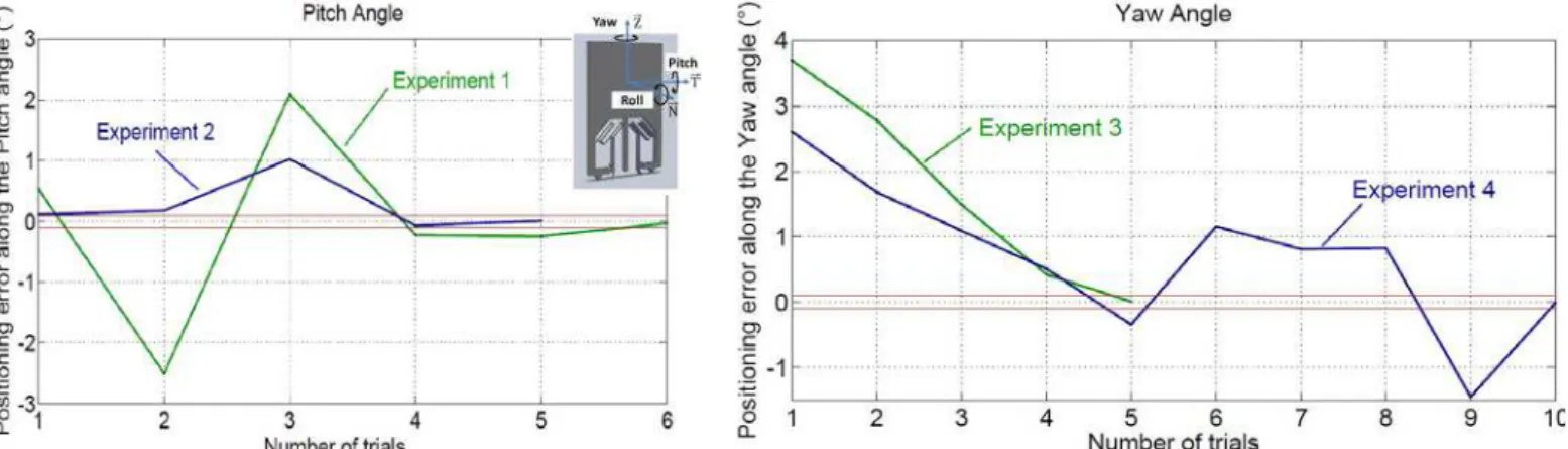
Fig. 5-a displays two typical results obtained applying this procedure for the Pitch angle. Red lines highlight the target to achieve (desired position) +/- 0.1°. They clearly show that it is possible to position a holder relative to the substrate with an error smaller than 0.1° along the pitch angle with a quite limited number of trials (6 for the first case i.e.
experiment 1 and 5 for experiment 2). Experimental results are displayed in table 2 and clearly show that all measurements (10 scanning cycles for every trial i.e. new position of the holder) have a maximum deviation smaller than +/- 0.005°. They also show that final positions of the holder (at the end of the process) are obtained with a positioning error of 0.034° and 0.009° for experiments 1 and 2 respectively.
Fig. 5-b displays two typical results obtained applying this procedure for the Yaw angle. They also clearly show that it is possible to position a holder relative to the substrate with an error smaller than 0.1° along the Yaw angle with a quite limited number of trials (5 for the first case i.e. experiment 3 and 10 for the second one i.e. experiment 4). Experimental results are also displayed in table 2 and also indicate that all measurement have a maximum deviation smaller than +/- 0.005°. They also show that final positions of the holder (at the end of the process) are obtained with a positioning error of 0.011° and 0.009° for experiments 3 and 4 respectively. This level of positioning accuracy is extremely interesting for Optical MEMS products and really enables to choose robotic micro-assembly to integrate optical functionalities in MEMS devices.
These experiments also enabled to establish that the relative position of the microgripper relative to the holder (during the gripping), force applied by the microgripper onto the holders springs during the assembly and the control of the roll angle are the three main influent parameters onto the positioning accuracy. These parameters are directly linked to the user experience. It thus appears as obvious that fully or partially automated assembly tasks will enable to obtain repetitive experimental conditions that would make experimental analysis more complete. Several works are being done notably to integrate force sensors and to achieve automated holders assembly based on hybrid force-position control [Komati et al. 2013]. Preliminary studies have been achieved but their application onto holder assembly still remains highly challenging and is being studied [Rabenorosoa et al. 2010].
IV Conclusions
This paper tackles the positioning accuracy characterization applied to micro-assembly tasks. Despite several teams successfully achieved micro-assembly tasks, the characterization of the position of a component obtained after robotic micro-assembly still remains extremely challenging. This paper firstly introduces the concept of micro-optical bench based on the micro-assembly of holders onto a substrate. Components (holders and substrate) have been fabricated and assembled using a complex robotized micro-assembly station. The proposed station is composed of several micropositioning stages used for large motions, nanopositioning stage to achieve fine relative positioning and one vacuum gripper to pick the components to be assembled from the substrate to the piezoelectric microgripper. This microgripper then achieves the final assembly of holders onto the substrate. The proposed micro-assembly station enables to accurately control all DoF of the holder position relative to the substrate. In addition, the microgripper being made of an active material and offering four DoF, it is then possible to achieve gripping and releasing tasks with good dexterity and to make them reversible. This micro-assembly station has been used to assemble micro-optical benches. Despite this interesting but qualitative aspect, a measurement set-up based on laser sensor measurement has been developed. It has then been integrated within the micro-assembly station to quantify the positioning accuracy of a holder to its substrate after assembly. The measurement set-up and methodology is proposed, tested and validated. It enables to achieve measurements with a precision as low as +/- 0.04° for the Yaw and +/-0.08° for the Pitch. The measurement set has then been integrated within the micro-assembly station to perform validation sequences.
Micro-assemblies have been performed and characterized. Ten measurements have been achieved for every new position of the holder showing deviation as low as +/- 0.005°. The use of an active material to actuate the microgripper enables to achieve reversible assemblies, then to improve the positioning accuracy when not satisfactory. Experimental results showed that a relative limited number of trials (10 in the worst case and 5 in the better one) have to be performed to guarantee a positioning error smaller than 0.1° for Yaw and Pitch angles. A positioning error of 0.009° has even been achieved for two experiments (one for the Yaw and one for the Pitch).
These results clearly show that robotic micro-assembly can be applied to manufacture complex MOEMS devices where positioning errors better than 0.1° is often required. These works have to be continued through the automation of the micro-assembly process to make it more constant and being able to quantify all parameters influence.
V Acknowledgment VI References
[Agnus et al. 2013] Agnus J., Chaillet N., Clévy C., Dembélé S., Gauthier M., Haddab Y., Laurent G. J., Lutz P., Piat N., Rabenorosoa K., Rakotondrabe M. and Tamadazte B. (2013) “Robotic Microassembly and micromanipulation at FEMTO-ST”, Journal of Micro-Nano Mechatronics, Vol. 20, No. 2, pp 91-106.
[Aljasem et al. 2008] Aljasem K., Werber A., Seifert A. and Zappe H. (2008) “Fiber optic tunable probe for endoscopic optical coherence tomography,” Journal of Optics A: Pure and Applied Optics, Vol. 10, No. 4, 044012.
[Aljasem et al. 2011] Aljasem K., Froehly L., Seifert A. and Zappe H. (2011) “Scanning and tunable micro-optics for endoscopic optical coherence tomography,” Journal of Microelectromechanical Systems, Vol. 20, No. 6, pp. 1462- 1472.
[Aoki et al. 2003] Aoki K., Miyazaki H. T., Hirayam H., Inoshit K., Baba T., Sakoda K., Shinya N. and Aoyagi Y. (2003) “Microassembly of semiconductor threedimensional photonic crystals”, Nature materials, Vol 2, pp 117-121.
[Bargiel et al. 2010] Bargiel S., Rabenorosoa K., Clévy C., Gorecki C. and Lutz P. (2010), “Towards Micro-Assembly of Hybrid MOEMS Components on Reconfigurable Silicon Free-Space Micro-Optical Bench”, Journal of Micromechanics
and Microengineering, Vol. 20, No. 4, 045012.
[Chaillet and Régnier 2010] Chaillet N. and Régnier S. (2010) Microrobotics for micromanipulation, Wiley.
[Clévy et al. 2011] Clévy C., Rakotondrabe M. and Chaillet N. (2011) Signal Measurement and Estimation Techniques
for Micro and Nanotechnology, ISBN 978-1-4419-9945-0, Springer.
[Das et al. 2012] Das A.N., Murthy R., Popa D. O., Stephanou H.E. (2012) “A Multiscale Assembly & Packaging System for Manufacturing of Complex Micro-nano Devices,” in IEEE Transactions on Automation Science and
Engineering, Vol. 9, No. 1, pp. 160-170.
[Dechev et al. 2004] Dechev N., Cleghorn W.L. and Mills J.K. (2004) “Microassembly of 3-d microstructures
using a compliant, passive microgripper”. Journal of Microelectromechanical Systems, Vol. 13, No. 2, pp. 176 – 189. [De Lit et al. 2004] De Lit P., Agnus J., Clévy C. and Chaillet N., (2004), “A four-degree-of-freedom microprehensile microrobot on chip”, Assembly and automation, Vol. 24, No. 1, pp.33-42.
[Fukuda et al. 2000] Fukuda T. and Arai F. (2000) “Prototyping Design and Automation of Micro/nano Manipulation System”, IEEE International Conference on Robotic and Automation, San Francisco, USA, pp. 192 – 197.
[Gauthier and Régnier 2010] Gauthier M. and Régnier S. (2010) Robotic micro-assembly, Wiley-IEEE Press.
[Ivan et al. 2009] Ivan A., Rakotondrabe M., Lutz P. and Chaillet N. (2009) “Current integration force and displacement self-sensing method for cantilevered piezoelectric actuators”, Review of Scientific Instruments, Vol. 80, No. 12, 2126103.
[Komati et al. 2013] Komati B., Rabenorosoa K., Clévy C. and Lutz P., (To appear, 2013, available online), “Automated Guiding Task of a Flexible Micropart Using a Two-Sensing-Fingers Microgripper”, IEEE Transactions on Automation
Science and Engineering, DOI: 10.1109/TASE.2013.2241761,
[Popa et al. 2007] Popa D. O., Murthy R., Das A. N., Lee W. H., Stephanou H. E., "High Yield Automated MEMS Assembly," in Proc. of IEEE CASE Conference, September 2007.
[Probst et al. 2007] Probst M., Borer R. and Nelson B.J. (2007) “A microassembly ystem for manufacturing hybrid mems”, in Proc. of the 12th IFToMM World Congress, Besancon, France.
[Rabenorosoa et al. 2009-a] Rabenorosoa K., Das A. N., Murthy R., Clévy C., Popa D. and Lutz P. (2009) “Precise motion control of a piezoelectric microgripper for microspectrometer assembly”, ASME IDETC-CIE International Design
Engineering Technical Conferences & Computers and Information in Engineering Conference, San Diego, United States.
[Rabenorosoa et al. 2009-b] Rabenorosoa K., Clévy C., Lutz P., Bargiel S., and Gorecki C. (2009) “A Micro-Assembly Station used for 3D Reconfigurable Hybrid MOEMS Assembly”, IEEE ISAM International Symposium on Assembly and
[Rabenorosoa et al. 2010] Rabenorosoa K., Clévy C., and Lutz P. (2010) “Hybrid Force/Position Control applied to Automated Guiding Tasks at the Microscale”, IEEE/RSJ IROS International Conference on Intelligent Robots and
Systems, Taipei, Taiwan.
[Rabenorosoa et al. 2011] Rabenorosoa K., Clévy C., Bargiel S., Mascaro J. P., Lutz P. and Gorecki C. (2011) “Modular and Reconfigurable 3D Micro-Optical Benches: Concept, Validation, and Characterization” ASME-MSEC
International Manufacturing Science & Ingineering Conference, Oregon State University Corvallis, USA.
[Rakotondrabe et al. 2010] Rakotondrabe M., Clévy C. and Lutz P. (2010) “Complete open loop control of hysteretic, creeped and oscillating piezoelectric cantilever”, IEEE - Transactions on Automation Science and Engineering, Vol.7, No. 3, pp. 440-450.
[Sariola et al. 2010] Sariola V., Jaaskelainen M., and Zhou Q. (2010) “Hybrid microassembly combining robotics and water droplet self-alignment,” IEEE Transactions on Robotics, Vol. 26, No. 6, pp. 965–977.
[Sun and Xie 2011] Sun J., and Xie H. (2011) "MEMS-Based Endoscopic Optical Coherence Tomography",
International Journal of Optics”, vol. 2011, no. 825629.
[Tan et al. 2013] N. Tan, C. Clévy and N. Chaillet (2013) “Calibration of Single-axis Nanopositioning Cell Subjected to
Thermal Disturbance” IEEE ICRA International Confrence on Robotics and Automation, Karlsruhe, Germany.
[Tan et al. 2012] N. Tan, C. Clévy, G. J. Laurent and N. Chaillet (2012) “Calibration and Validation of XYTheta
Micropositioners with Vision” IEEE/ASME AIM International Conference on Avanced Intelligent Mechatronics.
[Tamadazte et al. 2011] Tamadazte B.,. Piat N. L.-F, and Dembélé S. (2011) “Robotic micromanipulation and microassembly using monoview and multiscale visual servoing,” IEEE/ASME Transactions on Mechatronics, Vol. 16 No. 2, pp. 277 – 287.
[Tolfree and Jackson 2006] Tolfree D. and Jackson M. J. (2006) Commercializing Micro-Nanotechnology Products. CRC Press.
(a)
(b)
Fig1: (a) Concept and (b) Example of assembled micro-optical bench (the size of a holder is 1200x800 µm) [Bargiel et al. 2010].
X Y Z
(a) (b)
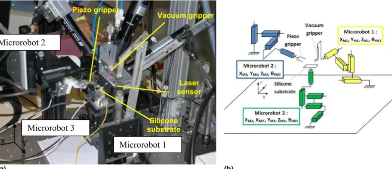
Fig 2: (a) Robotic micro-assembly system composed of one 4 DoF piezo gripper, one vacuum gripper, 16 micro or nanopositioning stages, the wafer has been removed for the picture (b) kinematic diagram of the micro-assembly system.
Microrobot 1
Microrobot 3
Microrobot 2
X Y Z Vacuum gripper Piezo gripper Silicone substrate Laser sensorFig. 3: (a) Close view of the substrate, microgrippers and laser sensor (b) 4 Degrees of Freedom piezoelectric microgripper (c) close view of a holder held by the vacuum gripper and before grasping by the piezo microgripper. Vacuum gripper tip Fingers of the piezo microgripper Holder Piezo actuator Passive fingers Laser sensor Vacuum gripper tip Camera Piezo microgripper Microrobot 3 Silicon substrate X Y Z X Y 1 mm 10 mm Microrobot 2
(a)
(b)
(c)
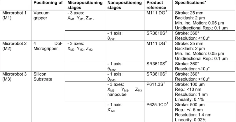
Positioning of Micropositioning stages Nanopositioning stages Product reference Specifications* Microrobot 1 (M1) Vacuum gripper - 3 axes: XM1, YM1, ZM1, M111 DG1 Stroke: 25 mm Backlash: 2 µm
Min. Inc. Motion: 0.05 µm Unidirectional Rep.: 0.1 µm - 1 axis: θYM1 SR3610S2 Stroke: 360° Resolution: <10µ° Microrobot 2 (M2) 4 DoF Microgripper - 3 axes: XM2, YM2, ZM2 M111 DG1 Stroke: 25 mm Backlash: 2 µm
Min. Inc. Motion: 0.05 µm Unidirectional Rep.: 0.1 µm - 1 axis: θXM2 SR3610S2 Stroke: 360° Resolution: <10µ° Microrobot 3 (M3) Silicon Substrate - 1 axis: θZM3 SR3610S2 Stroke: 360° Resolution: <10µ° - 3 axes: XM3, YM3, ZM3 nanocube P611.3S1 Stroke: 100 µm Rep.: <10 nm Resolution: 1 nm Linearity: 0.1% - 1 axis: X’M3 P625.1CD1 Stroke: 500 µm Rep.: +/- 5 nm Resolution: 1.4 nm Linearity: 0.02% Table 1: Composition and performances of the 3 microrobots.
1
From PI (Physik Instrumente) GmbH & Co. KG
2
From Smaract GmbH
Fig. 4: (a) Calibration of the set-up based on laser scanning of a reference hole to define the reference frame (b) Square scanning of the holder with the laser sensor to quantify the position of the holder relative to the reference frame.
Laser spot
Springs
Trajectory
of the laser
(b)
(a)
Fig. 5: Experimental results: (a) positioning error along the Pitch angle: experiment 1 requiring 6 trials to reach the target (0°+/- 0.1°) and experiment 2 requiring 5 trials (b) positioning error along the Yaw angle: experiment 3 requiring 5 trials to reach the target (0°+/- 0.1°) and experiment 4 requiring 10 trials.
Experiment 1 Pitch (°) 0.537 -2.508 2.097 -0.229 -0.246 -0.034 Max deviation (°) ±0.002 ±0.005 ±0.003 ±0.004 ±0.005 ±0.004 Experiment 2 Pitch (°) 0.113 0.178 1.023 -0.071 0.009 Max deviation (°) ±0.004 ±0.004 ±0.005 ±0.003 ±0.003 Experiment 3 Yaw (°) 3.702 2.784 1.492 0.42 0.011 Max deviation (°) ±0.004 ±0.005 ±0.004 ±0.002 ±0.002 Experiment 4 Yaw (°) 2.607 1.685 1.09 0.506 -0.344 1.155 0.809 0.828 -1.454 -0.009 Max deviation (°) ±0.004 ±0.004 ±0.005 ±0.003 ±0.003 ±0.003 ±0.004 ±0.005 ±0.002 ±0.002