Titre:
Title
: High gain slot array with Fabry-Perot cavity feeding circuit
Auteurs:
Authors
: Halim Boutayeb et Mourad Nedil
Date: 2016
Type:
Article de revue / Journal articleRéférence:
Citation
:
Boutayeb, H. & Nedil, M. (2016). High gain slot array with Fabry-Perot cavity feeding circuit. International Journal of Antennas and Propagation, 2016, p. 1-5. doi:10.1155/2016/9674742
Document en libre accès dans PolyPublie
Open Access document in PolyPublieURL de PolyPublie:
PolyPublie URL: https://publications.polymtl.ca/3503/
Version: Version officielle de l'éditeur / Published versionRévisé par les pairs / Refereed Conditions d’utilisation:
Terms of Use: CC BY
Document publié chez l’éditeur officiel
Document issued by the official publisherTitre de la revue:
Journal Title: International Journal of Antennas and Propagation Maison d’édition:
Publisher: Hindawi URL officiel:
Official URL: https://doi.org/10.1155/2016/9674742 Mention légale:
Legal notice:
Ce fichier a été téléchargé à partir de PolyPublie, le dépôt institutionnel de Polytechnique Montréal
This file has been downloaded from PolyPublie, the institutional repository of Polytechnique Montréal
Research Article
High Gain Slot Array with Fabry-Perot Cavity Feeding Circuit
Halim Boutayeb
1and Mourad Nedil
21Ecole Polytechnique de Montr´eal, 2500 Ch. de Polytechnique, Montr´eal, QC, Canada H3T 1J4 2Universit´e du Qu´ebec en Abitibi-T´emiscamingue, Val-d’Or, QC, Canada J9P 1Y3
Correspondence should be addressed to Halim Boutayeb; [email protected] Received 11January 2016;Accepted 13 June 2016
Academic Editor: Paolo Burghignoli
Copyright © 2016H. Boutayeb and M. Nedil. This is an open access article distributed under the Creative Commons Attribution License, which permits unrestricted use, distribution, and reproduction in any medium, provided the original work is properly cited.
A new approach for designing slot arrays using a Fabry-Perot cavity for the feeding circuit is presented. Th proposed array has simpler and smaller feeding circuit compared to conventional feeding networks that have multiple dividers or combiners. Th dividers and combiners are usually sources of losses. In addition, the profile of the proposed array is not limited by the half-wavelength resonance condition that exists for Fabry-Perot resonator antennas based on partially refle ting surfaces. The operating frequency is not sensitive to the profile of the antenna. A small profile can be achieved without the utilization of an artificial magnetic conductor or a substrate with high dielectric constant. To validate the proposed approach, full-wave numerical results are presented at 5.8 GHz showing good impedance matching, a high gain of about 22 dB, and an efficie y of 76%.
1. Introduction
Low-cost single-feed directive antennas are essential to several wireless communication systems, such as satellites, various point-to-point links, and high-speed wireless LANs. Thei single-feed system allows increasing the gain with low complexity and less loss compared to feeding networks used in conventional antenna arrays.
Among single-feed directive antennas, Fabry-Perot res-onator antennas have attracted significant attention, in the past few years, in microwave and millimeter wave domains. Thi is because these antennas have a number of interesting properties, such as low profile, low complexity, low loss, high directivity, and conformal deployment capability [1–4].These types of antennas can be analyzed using different models: ray tracing/ray launching, Electromagnetic Band Gap (EBG) defect, leaky-wave, transmission line, and refractive lens models [5–7].
In a Fabry-Perot resonator antenna, the cavity can be mainly fi led with air [8–11],or it can be fully filled with a planar single-layer dielectric slab [12–14]. Th latter structure with full dielectric integration poses several design chal-lenges, particularly for high-permittivity substrates, includ-ing increased dielectric loss, lowered directivity caused
by small-volume antennas, poor surface-wave efficie y, and narrow 3 dB gain bandwidth compared with the air-filled Fabry-Perot resonator antenna. Nevertheless, such an antenna configur tion is still considered a promising can-didate, due to its smaller volumetric occupation compared with other substrate-lens designs [15]. It also presents a number of other advantages, such as low profile and low cost, mechanical robustness, good integration, and stable fabrication and installation. Fabry-Perot cavity antennas with a very small distance between the planar feed and the partially refle ting surface (PRS) have been reported in [16, 17]. However, the design suffers from a tiny gap between the two closely apprised substrates, and a resonance frequency shift could thus present an ineluctable problem. In [18], a Fabry-Perot resonator cavity antenna made of a high-permittivity substrate and excited by a planar leaky-wave slit has been proposed as an alternative.
Another interesting solution for designing a high gain antenna without a feeding network consists in using a single patch having a rectangular profile and a genetic algorithm optimization to replace the array [19, 20].
In this work, a new technique for designing high gain antenna is proposed. The excitation structure is composed of a Fabry-Perot cavity and the radiators are slots. The proposed
Volume 2016, Article ID 9674742, 5 pages http://dx.doi.org/10.1155/2016/9674742
2 International Journal of Antennas and Propagation Py Wf Wy Px Dy Dx Ax Pf x z y Ay (a) x z y H Coaxial line (b)
Figur e 1:Slot array excited by using a Fabry-Perot cavity feeding circuit: (a) top view; (b) side view.
array has simpler and smaller feeding circuit compared to conventional feeding networks that have multiple dividers or combiners, which are causing losses. Also, the profile of the array is not limited by the half-wavelength resonance condition that exists for Fabry-Perot resonator antennas based on partially refle ting surfaces. A small profile can be achieved without the utilization of a high-permittivity substrate or an artifici l magnetic conductor.
The paper is organized as follows. First, the actual prototype of the antenna is described. Second, full-wave numerical results are presented to validate the design. Finally, concluding remarks are given.
2. Antenna Design
Figure 1presents the main views of the antenna array that is used to validate the proposed concept. This antenna is made of a parallel plate waveguide excited by a probe connected to coaxial line; cross-slots are on one wall of the parallel plate waveguide and a Fabry-Perot cavity made of metallic wires is used in order to distribute the fields equally in phase and amplitude in the radiating slots disposed in the same column. The following are the main parameters of the array. 𝑊𝑓 is the width of the Fabry-Perot cavity and 𝑃𝑓 is the period for the metallic wires. 𝑊𝑦 is the distance between two adjacent cross-slots that are on each side of the cavity. 𝑃𝑦 is the periodic distance in 𝑦 direction between other adjacent cross-slots. 𝑃𝑥 is the period between adjacent cross-slots in 𝑥 direction. 𝐷𝑦 and 𝐷𝑥 are the positions of short-circuits of the waveguide in 𝑦 and 𝑥 direction, respectively. 𝐴𝑥 and 𝐴𝑦 are dimensions in 𝑥𝑦 plane. 𝐻 is the height of the parallel plate waveguide.
Figure 2 presents in more detail the probe excitation, the position of the cross-slots, and the cross-slots parameters. 𝐷𝑤 is the diameter of the wires of the Fabry-Perot cavity. 𝐷𝑝 and 𝐻𝑝are the diameter and the height of the probe, respectively.
𝐿is the length of the slots, 𝑊𝑠 is the slot width, 𝜑 and −𝜑 are the angles of rotation of the slots, and 𝑆 is the shift distance between two rectangular slots that belongs to the same cross-slot.
𝑊𝑓 controls the resonance of the Fabry-Perot cavity (about half wavelength), whereas 𝑆 plays a role in the cross-polarization discrimination. 𝑃𝑦 is about one wavelength distance and 𝑃𝑥 is about half wavelength. At the resonance of the Fabry-Perot cavity, cross-slots that are in the same 𝑦 coordinate receive fields with the same phase [5]. Th wavelength size of 𝑃𝑦 allows for the radiating slots to radiate field at the same phase when the wave propagates in the 𝑦 direction, such as a traveling wave antenna array. The dimensions of the antenna parameters were obtained using a quasi-Newton optimization algorithm for maximising the gain with good impedance matching.
3. Full-Wave Numerical Results
Th proposed antenna was simulated with a full-wave simu-lator (ANSYS HFSS). The following are the chosen values of the antenna parameters for operating at 5.8 GHz: 𝐻 = 10 mm, 𝐴𝑦= 437 mm, 𝐴𝑥 = 400 mm, 𝐷𝑤 = 1mm, 𝐷𝑝 = 6 mm, 𝐻𝑝 = 4.6 mm, 𝑊𝑓 = 20.5 mm, 𝑊𝑦 = 54 mm, 𝑃𝑓 = 20.5 mm, 𝑃𝑦 = 50 mm, 𝑃𝑥 = 26.5 mm, 𝐷𝑥 = 14 mm, 𝐷𝑦 = 41.5mm, 𝐿 = 25 mm, 𝑆 = 2 mm, 𝑊𝑠 = 4 mm, and 𝜑 = 70∘.
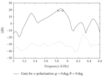
Figure 3 illustrates the simulated refle tion coeffici t of the antenna. A matching bandwidth (𝑆11 < −10dB) from 5.6 GHz to 6.04 GHz (a fractional bandwidth of 7.6%) is achieved. The simulated broadside gain versus frequency of the antenna is shown in Figure 4 for 𝑥-polarization and 𝑦-polarization. A maximum gain of 22 dB is achieved around 5.85 GHz (the radiation efficie y is about 76%). The 3 dB gain bandwidth is about 2.05%. This bandwidth needs to be increased to obtain a broadband high gain antenna. For this, different approach will be discussed later. Th maximum
PEC surfaces Probe Coaxial line Metallic wire with diameter Dw Dp Hp H (a) Wf Wy (b) S L Ws 𝜑 (c)
Figur e 2: Details of the proposed antenna: (a) probe excitation; (b) Fabry-Perot cavity and position of cross-slots; (c) cross-slot design details.
5 5.2 5.4 5.6 5.8 6 6.2 6.4 6.6 −40 −35 −30 −25 −20 −15 −10 −5 0 Frequency (GHz) (dB)
Figur e 3: Simulated return loss of the antenna array. Bandwidth for 𝑆11 < −10dB is shown.
cross-polarization gain of the antennas is approximately 45 dB below one of the copolarization values.
Th 3D pattern of the simulated antenna gain at 5.85 GHz is shown in Figure 5, whereas Figures 6 and 7 show the gain patterns at 5.85 GHz of the antenna, in 𝑥𝑧 and 𝑦𝑧 planes, respectively. In 𝑦𝑧 plane, the directivity is due to the travelling wave radiation, whereas in 𝑥𝑧 plane, the directivity is due to the Fabry-Perot cavity.
To illustrate further the directivity mechanism, Figure 8 shows the electric current distribution at the surface of the slots. From this figure, it can be seen that the current distribution along 𝑥𝑧 plane is similar to the field distribution observed in a PRS of a Fabry-Perot resonator antenna [7].
In 𝑥𝑧 planes the field distribution is due to the func-tionality of the Fabry-Perot cavity with a quasi-uniform distribution. In the 𝑦𝑧 plane, the energy is radiated by
4 International Journal of Antennas and Propagation 5 5.2 5.4 5.6 5.8 6 6.2 6.4 6.6 −50 −40 −30 −20 −10 0 10 20 30 Frequency (GHz) (dB)
Gain for x-polarization, 𝜑 = 0 deg, 𝜃 = 0 deg Gain for y-polarization, 𝜑 = 0 deg, 𝜃 = 0 deg
Figur e 4: Simulated 𝑥-component (copolarization) and 𝑦-com-ponent (cross-polarization) of total gain versus frequency. 3 dB gain bandwidth is shown. x z y dB (GainTotal) 2.1972e + 01 2.0403e + 01 1.8834e + 01 1.7264e + 01 1.5695e + 01 1.4125e + 01 1.2556e + 01 1.0986e + 01 9.4168e + 00 7.8473e + 00 6.2779e + 00 4.7084e + 00 3.1389e + 00 1.5695e + 00 0.0000e + 00 𝜑 𝜃
Figur e 5: Simulated 3D total gain pattern of the antenna at 5.85 GHz. −150 −100 −50 0 50 100 150 −10 −5 0 5 10 15 20 25 Ga in (dB) 𝜃(deg)
Figur e 6: Simulated gain in 𝑦𝑧 plane at 5.85 GHz.
−150 −100 −50 0 50 100 150 −10 −5 0 5 10 15 20 25 Ga in (dB) 𝜃(deg)
Figur e 7: Simulated gain in 𝑥𝑧 plane at 5.85 GHz.
Jsurf[A_per_m] 5.0000e − 01 4.6429e − 01 4.2857e − 01 3.9286e − 01 3.5714e − 01 3.2143e − 01 2.8571e − 01 2.5000e − 01 2.1429e − 01 1.7857e − 01 1.4286e − 01 1.0714e − 01 7.1429e − 02 3.5714e − 02 0.0000e + 00
Figure 8: Electric current distribution at the surface of the slot array at 5.85 GHz.
the slots in the manner of a travelling wave antenna except there is no metallic wall like in usual waveguides. By using different synthesis techniques, the field distribution could be optimized for reducing the side lobes observed in both planes (Figures 6 and 7).
It should be noted that the proposed concept can be used with other types of sources, for example, a substrate integrated waveguide with a transition from a microstrip line, in order to design the antenna with a single layer. Furthermore, the same principles as those used in [21–23] for a nonperiodic PRS or with multiple PRSs could be used for feeding a slot array. The e techniques could be used to increase the gain bandwidth and the efficiency of the antenna. Finally, the slots along the 𝑦 direction can be designed using more advanced techniques that are usually used for travelling-wave antennas, such as in [24].
4. Conclusion
A new slot array with a Fabry-Perot cavity feeding circuit has been proposed and analyzed. Th proposed concept has been validated with full-wave simulations. This type of antenna can be integrated with other printed and/or lumped passive and
active components on the same board and therefore proposes a promising solution for RF/microwave and millimeter wave technologies.
Competing Interests
The authors declare that they have no competing interests.
References
[1] G. von Trentini, “Partially reflecti g sheet arrays,” IRE
Transac-tions on Antennas and Propagation, vol. 4, no. 4, pp. 666–671,
1956.
[2] A. P. Feresidis and J. C. Vardaxoglou, “High gain planar antenna using optimised partially refle tive surfaces,” IEE Proceedings:
Microwaves, Antennas and Propagation, vol. 148, no. 6, pp. 345–
350, 2001.
[3] H. Boutayeb, K. Mahdjoubi, A.-C. Tarot, and T. A. Denidni, “Directivity of an antenna embedded inside a Fabry-Perot cavity: analysis and design,” Microwave and Optical Technology
Letters, vol. 48, no. 1, pp. 12–17, 2006.
[4] Z.-G. Liu and Y.-X. Guo, “Effect of primary source location on fabry-perot resonator antenna with PEC or PMC ground plate,”
Journal of Infrared, Millimeter, and Terahertz Waves, vol. 31, no.
9, pp. 1022–1031, 2010.
[5] H. Boutayeb, “Comparison between two semi-analytical meth-ods for computing the radiation characteristics of a Fabryperot cavity,” Microwave and Optical Technology Letters, vol. 48, no. 8, pp. 1654–1656, 2006.
[6] Z.-G. Liu, “Fabry-perot resonator antenna,” Journal of Infrared,
Millimeter, and Terahertz Waves, vol. 31, no. 4, pp. 391–403, 2010.
[7] H. Boutayeb, “Comparison between ray tracing and ray launch-ing semianalytical methods for computlaunch-ing the radiation char-acteristics of a Fabry-Perot cavity,” Microwave and Optical
Technology Letters, vol. 57, no. 1, pp. 13–15, 2015.
[8] H. Ostner, E. Schmidhammer, J. Detlefsen, and D. R. Jackson, “Radiation from dielectric leaky-wave antennas with circular and rectangular apertures,” Electromagnetics, vol. 17, no. 5, pp. 505–535, 1997.
[9] Y. Lee, X. Lu, Y. Hao, S. Yang, J. R. G. Evans, and C. G. Parini, “Low-profile directive millimeter-wave antennas using free-formed three-dimensional (3-D) electromagnetic bandgap structures,” IEEE Transactions on Antennas and Propagation, vol. 57, no. 10, pp. 2893–2903, 2009.
[10] H. Liu, S. Lei, X. Shi, and L. Li, “Study of antenna superstrates using metamaterials for directivity enhancement based on Fabry-Perot resonant cavity,” International Journal of Antennas
and Propagation, vol. 2013, Article ID 209741, 10 pages, 2013.
[11] S. A. Hosseini, F. Capolino, and F. De Flaviis, “Gain enhance-ment of a V-band antenna using a Fabry-Perot cavity with a self-sustained all-metal cap with FSS,” IEEE Transactions on
Antennas and Propagation, vol. 63, no. 3, pp. 909–921, 2015.
[12] S. A. Hosseini, F. Capolino, and F. De Flaviis, “A 44 GHz single-Feed Fabry-P´erot Cavity antenna designed and fabricated on quartz,” in Proceedings of the IEEE International Symposium
on Antennas and Propagation and USNC/URSI National Radio Science Meeting (APSURSI ’11), pp. 1285–1288, Spokane, Wash,
USA, July 2011.
[13] T. K. Nguyen and I. Park, “Compact slit antenna incorporated with frequency selective surface,” in Proceedings of the IEEE
Global Symposium on Millimeters Waves (GSMM ’14), pp. 30–
31, Seoul, Republic of Korea, 2014.
[14] S. A. Hosseini, F. Capolino, and F. De Flaviis, “Q-band single-layer planar Fabry-P´erot cavity antenna with single integrated-feed,” Progress In Electromagnetics Research C, vol. 52, pp. 135– 144, 2014.
[15] O. M. Haraz, A. R. Sebak, and S. Alshebeili, “Study the effect of using low-cost dielectric lenses with printed log-periodic dipole antennas for millimeter-wave applications,” International
Jour-nal of Antennas and Propagation, vol. 2015, Article ID 209430, 7
pages, 2015.
[16] Y. Sun, Z. N. Chen, Y. Zhang, H. Chen, and T. S. P. See, “Sub-wavelength substrate-integrated Fabry-P´erot cavity antennas using artificial magnetic conductor,” IEEE Transactions on
Antennas and Propagation, vol. 60, no. 1, pp. 30–35, 2012.
[17] L. Li, S. Lei, and C.-H. Liang, “Ultra-low profil high-gain Fabry-Perot resonant antennas with fishnet superstrate,” Journal
of Electromagnetic Waves and Applications, vol. 26, no. 5-6, pp.
806–816,2012.
[18] T. K. Nguyen and I. Park, “Design of a substrate-integrated Fabry-P´erot cavity antenna for K-band applications,”
Interna-tional Journal of Antennas and Propagation, vol. 2015, Article ID
373801,12 pages, 2015.
[19] J. W. Jayasinghe, J. Anguera, D. N. Uduwawala, and A. And´ujar, “Nonuniform overlapping method in designing microstrip patch antennas using genetic algorithm optimization,”
Interna-tional Journal of Antennas and Propagation, vol. 2015, Article ID
805820, 8 pages, 2015.
[20] J. W. Jayasinghe, J. Anguera, and D. Uduwawala, “Genetic algorithm optimization of a high-directivity microstrip patch antenna having a rectangular profil ,” Radioengineering, vol. 22, no. 3, pp. 700–707, 2013.
[21] H. Boutayeb, T. A. Denidni, and M. Nedil, “Bandwidth widen-ing techniques for directive antennas based on partially refle t-ing surfaces,” Progress In Electromagnetics Research, vol. 74, pp. 407–419, 2007.
[22] H. Boutayeb, K. Mahdjoubi, and A.-C. Tarot, “Multi-layer crystals of metallic wires: analysis of the transmission coeffici t for outside and inside excitation,” Progress in Electromagnetics
Research, vol. 59, pp. 267–297, 2006.
[23] H. Boutayeb and T. A. Denidni, “Analysis and design of a high-gain antenna based on metallic crystals,” Journal of
Electromag-netic Waves and Applications, vol. 20, no. 5, pp. 599–614, 2006.
[24] H. Boutayeb and K. Wu, “Analysis and design of millimeter-wave circularly polarized substrate integrated travelling-millimeter-wave antennas,” Progress in Electromagnetics Research C, vol. 49, pp. 67–77, 2014.
Internatfional Journal of
A
e
ro
spa
c
e
Eng
fin
e
e
r
fing
H findawfi Publfishfing Corporatfion
http://www.hfindawfi.com Volume 2014
Robo
Journal ot
fics
fH findawfi Publfishfing Corporatfion
http://www.hfindawfi.com Volume 2014
H findawfi Publfishfing Corporatfion
http://www.hfindawfi.com Volume 2014
Actfive and Passfive Electronfic Components
Control Scfience and Engfineerfing
Journal of
H findawfi Publfishfing Corporatfion
http://www.hfindawfi.com Volume 2014
Internatfional Journal of
Rotatfing Machfinery
H findawfi Publfishfing Corporatfion
http://www.hfindawfi.com Volume 2014 H
findawfi Publfishfing Corporatfion http://www.hfindawfi.com
Journal of
En
g
fin
e
er
fin
g
Volume 2014
Subm
fi
t
your
manuscr
fip
ts
a
t
h
t
tp
:
/
/www
.h
findaw
fi
.com
VLSI Desfign
Hfindawfi Publfishfing Corporatfion
http://www.hfindawfi.com Volume 2014
H findawfi Publfishfing Corporatfion
http://www.hfindawfi.com Volume 2014
Shock and Vfibratfion
H findawfi Publfishfing Corporatfion
http://www.hfindawfi.com Volume 2014
C
Advancesfiv
fi
l
Eng
finfinee
r
fing
AcousAdvancestficsfin and Vfibratfion
H findawfi Publfishfing Corporatfion
http://www.hfindawfi.com Volume 2014 H
findawfi Publfishfing Corporatfion
http://www.hfindawfi.com Volume 2014
Electrfical and Computer
Engfineerfing
Journal of
Advancesfin OptoElectronfics
Hfindawfi Publfishfing Corporatfion
http://www.hfindawfi.com Volume 2014
The
Sc
fient
fific
Wor
ld
Journa
l
H findawfi Publfishfing Corporatfion
http://www.hfindawfi.com Volume 2014
Senso
JouHfindawfi Publrnafishfing Corporatl ofionfrs
http://www.hfindawfi.com Volume 2014
Modellfing & Sfimulatfion fin Engfineerfing
Hfindawfi Publfishfing Corporatfion
http://www.hfindawfi.com Volume 2014
H findawfi Publfishfing Corporatfion
http://www.hfindawfi.com Volume 2014
Chemfical Engfineerfing
InternatfionalJournal of Antennas and
Propagatfion
InternatfionalJournal of
H findawfi Publfishfing Corporatfion
http://www.hfindawfi.com Volume 2014 H findawfi Publfishfing Corporatfion
http://www.hfindawfi.com Volume 2014
Navfigatfion and Observatfion
InternatfionalJournal of
H findawfi Publfishfing Corporatfion
http://www.hfindawfi.com Volume 2014