Detection of Defects in Concrete
with Ground Penetrating Radar
*Audrey VAN DER WIELEN1, Luc COURARD2, Frédéric NGUYEN2
1)
FNRS Research Fellow, University of Liege, Belgium, e-mail: avdwielen@ulg.ac.be 2)
University of Liege, Belgium
KEY-WORDS
GPR, radar, thin layer, NDT, reflection
ABSTRACT
Ground Penetrating Radar (GPR) is a nondestructive technique particularly well adapted to the inspection of concrete structures and can help to determine the structure inner geometry or to detect damaged areas. When the GPR is used on structures containing thin layers, for example the sealing layer of a bridge or the void into a masonry wall, it is important for the radar user to know the minimum thickness required to detect and estimate the thickness of those layers.
The theory of thin layer detection is based on a sine wave but, in reality, the GPR emits a complicated pulse, which undergoes attenuation into the layer. To see the influence of those realistic conditions on the reflection coefficient of a thin layer, we combined experimental measurements and numerical FDTD simulations. The experimental results matched the numerical predictions well, presenting a fast attenuation compared to the theoretical predictions. Nevertheless, for thicknesses inferior to λ/11, the reflection coefficient could still be considered as linearly dependent of the thickness to wavelength ratio.
1. INTRODUCTION
Concrete structures can be attacked by diverse deterioration mechanisms, such as carbonation, alkali-aggregate reactions or corrosion. They have to be frequently inspected in order to be able to repair the damaged areas and establish the structural causes of the problem. During those inspections, non-destructive techniques are particularly interesting because they permit to test large surfaces and they highly limit the number of cores that have to be extracted from the structure. Among all the non-destructive methods, the Ground Penetrating Radar (GPR) is well adapted to inspect multilayer structures. In this study, we tried to evaluate numerically and experimentally the minimum thickness that could be detected by the GPR.
2.
PRINCIPLE OF GROUND PENETRATING RADAR
2.1
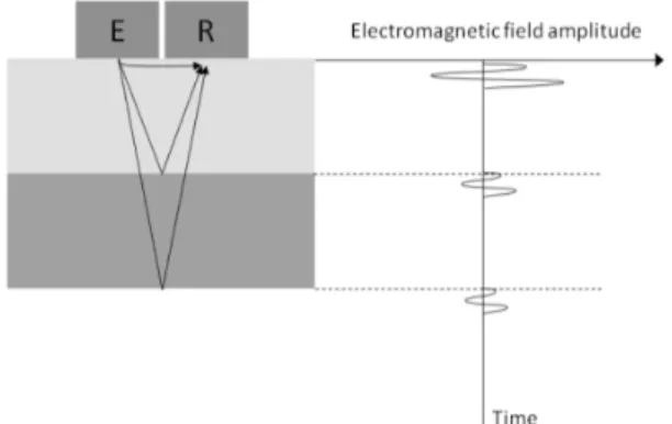
General PrincipleThe principle of GPR is to send, with an emitter antenna, very short electromagnetic pulses through the ground or the structure. Those pulses propagate to all directions and are reflected when they meet interfaces between media of different electromagnetic properties. A receiver antenna measures the amplitude of the signal over time (Figure 1). On the resulting scan, both the direct wave and the waves reflected on the different interfaces can be observed. This method allows detecting voids, humid zones and material modifications.
Figure 1: Simplified GPR signal measured on a two-layer structure
2.2 Radar wave speed estimation
If the conductivity of the material can be neglected (which is often the case for usual building materials [1]), the wave speed v is directly dependant of the relative dielectric permittivity of the material ε’r (with c the speed of light, equal to 30 cm/ns):
ݒ = ܿ
ඥεr′ (1) Different methods are available to estimate the speed and thus the dielectric permittivity of concrete:
• By measuring the time elapsed between the emission of the pulse and the reception of its echo, the depth of the interface can be determined if the speed of the waves is known, and vice-versa.
• The measurement can be directly performed with two antennas (common mid-point measurement). The speed is then the slope of the time-versus-distance line. • The speed can also be estimated from the shape of the hyperbolas resulting from
a punctual defect’s detection.
In this work, we chose to determine directly the dielectric permittivity of the concrete by using the reflection properties of the surface. Indeed, the reflection
coefficient, which is the proportion of the incident wave reflected by an interface, depends on the permittivites of the two media:
ܴ =cos ߠ1− ටߝ ݎ2
ߝݎ1− sin2ߠ1 cos ߠ1+ ටߝߝݎ1ݎ2− sin2ߠ1
(2) In (2), derived from the Fresnel reflection coefficients [1], εr1 and εr2 are the respective relative dielectric permittivity of the two materials and θ1 is the inclination of the incident ray. If we measure the reflection amplitude of the surface from a certain distance, εr1=1 (material 1 is air) and the inclination can be approximated to zero. The reflection coefficient is obtained by dividing the reflected amplitude by the amplitude measured from the same distance on a perfect reflector; it thus univocally determines the dielectric permittivity of the concrete surface, from which it is possible to calculate the speed in the material. The drawback of this method is the fact that it only reveals the permittivity of the surface. If a gradient is present, the mean permittivity will be different from the surface permittivity, and the depth of the detected features could then be misevaluated.
3. DETECTION LIMITS OF THIN LAYERS
In many concrete structures, features presenting a small thickness to surface ratio are relatively common, i.e. the sealing layer of a bridge or the void into a masonry wall. It is thus important for the radar user to know the minimum thickness required to detect thin layers and estimate their thicknesses.
3.1 Theoretical approach
Thin layers are difficult to detect, because the incident radar waves (I) undergo multiple reflections on the two limit interfaces, which generates constructive and destructive interferences (Figure 3).
Figure 3: Multiple reflections in a thin layer
The theoretical reflection coefficient (Figure 2b) oscillates thus between 0 and a maximum value R121:
R121=1 + R2R12
122 . (3) In (3), R121 is the reflection coefficient for a thin layer, while R12 is the coefficient corresponding to the reflection on a simple interface between the two media (Equation. (2)). The first maximum occurs when the layer thickness is equal to a quarter of the wavelength in the layer λ, and has then a periodicity of λ/2. The reflection occurring on the thin layer has then a greater amplitude than a reflection that would occur on a simple interface. The evolution of R121 with the ratio of the layer thickness on the wavelength in the thin layer is drawn in Figure 4.
Figure 4: Reflection coefficient for an air thin layer into concrete
For the very thin layers, we observe a linear relationship between the reflection coefficient and the thickness on wavelength ratio.
3.2 Experimental and numerical evaluation of the thin layer reflection coefficient
The theory of thin layer detection [1] is based on a sine wave but, in reality, the GPR emits a complicated pulse, which undergoes attenuation into the layer. To see the influence of those realistic conditions on the reflection coefficient of a thin layer, we combined experimental measurements and numerical simulations.
The simulations were performed with finite differences program GprMax [2] and dielectric permittivity of concrete was estimated using the surface reflection method described in paragraph 2.2. A realistic incident wavelet derived from the direct signal of our 2.3 GHz antenna was introduced in the program. The reflection coefficient (R) was obtained from those simulations by dividing all the reflected peak-to-peak amplitudes by the amplitude reflected on a perfect reflector placed at the same depth.
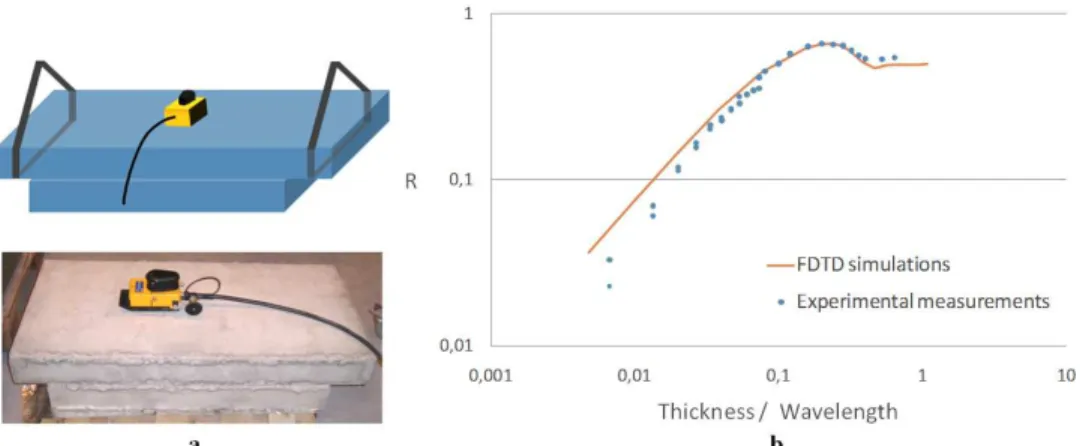
The experimental measurements were performed on two smooth concrete slabs separated by plastic or wooden spacers of variable thicknesses, leaving a controlled air layer under the measurement point. As for the numerical results, all the reflected amplitudes were divided by the amplitude reflected on a metallic sheet, supposed to be a perfect reflector, placed at the same depth, in order to obtain the reflection coefficient. The experimental setup and the results are displayed in Figure 5.
Figure 5: (a) Experimental setup; (b) Comparison between experimental measurements and numerical data
The reflection coefficient revealed to be linearly dependent on the thickness on wavelength ratio for thicknesses less than λ/11; some small discrepancies are observed, probably due to the surface imperfections.
4. CONCLUSION
In this study, we tried to evaluate the reflection coefficient of a thin layer into concrete, in order to estimate the detection limit of our antenna.
The reflection coefficient revealed to be linearly dependent on the thickness-on-wavelength ratio for thicknesses less than λ/11; some small discrepancies were observed, probably due to the small surface imperfections. Anyway in our study, thicknesses inferior to λ/100 were visible with the GPR.
We also showed that numerical simulation performed with a realistic impulsion and measured concrete properties could match real measurements very well and help to interpret experimental results.
By this method, the amplitude reflected by a thin layer can be estimated. The layer will then be visible if this reflected amplitude, after subtraction of the losses (including the intrinsic and geometric attenuations), is superior to the signal noise.
ACKNOWLEDGEMENTS
We thank the FNRS (National Found for Scientific Research in Belgium) for founding and Mr Lucien Dormal from Ronveaux S.A., who casted the smooth slabs.
REFERENCES
1. Annan A. P.: Ground-Penetrating Radar, Near-Surface Geophysics Part 1: Concepts and Fundamentals, Society of Exploration Geophysicists, D. K. Butler, 2005, pp. 357- 438
2. Giannopoulos A.: Modelling Ground Penetrating Radar by GprMax, Construction and Building materials, vol. 19 (2005), no. 10, pp. 755-762