Seismic Assessment and Retrofitting of an S Shape Building with
Expansion Joints.
A. Plumier1, V. Denoël1, L. Sanchez1, C. Doneux1, V. Warnotte1, W. Van Alboom2 1
Department of Mechanics of Materials and Structures, University of Liege, Belgium 2
SECO, Technical Control bureau for Construction, rue d'Arlon, 53 1040 Brussels, Belgium
ABSTRACT: An elastic analysis of an existing 20-storey reinforced concrete moment resisting frame divided in 3 blocks shows that beams supported on corbels of the adjacent block at the expansion joint loose their support when each independent block vibrate on its own under earthquake. Different reconnection hypothesis were considered, ranging from fixing totally each block to the adjacent one to more flexible options leaving some free relative move between blocks. An elastic modal superposition followed by a pushover analysis considering the final reconnection principle were made. The degrees of freedom of the joint reconnections were observed to be an important parameter. The solution found leaves a free relative rotational move between blocks and a flexible translational movement, so that forces at the connection do not become uselessly high. The springs used (long tie rods) work essentially elastically so that no permanent relative displacement exists between blocks after an earthquake.
1 INTRODUCTION
Building collision, commonly called ‘pounding’, occurs during an earthquake when, due to their different dynamic characteristics, adjacent buildings vibrate out of phase and the at-rest separation is insufficient to accommodate their relative motions. Pounding between adjacent structures such as buildings or bridges or between parts of the same structure during major earthquakes has often been reported. Both high and low-rise inadequately separated adjacent structures are susceptible to damages induced by poundings.
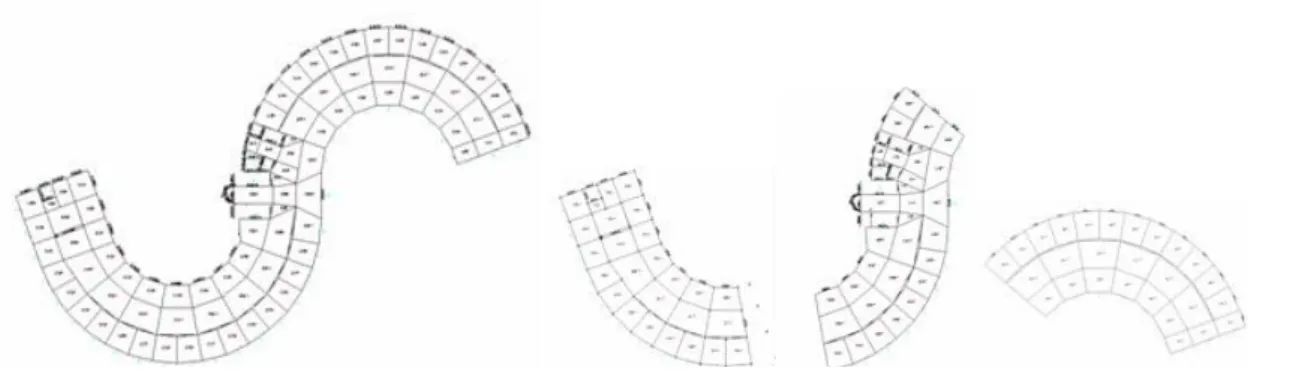
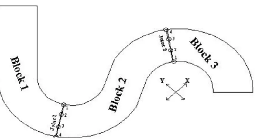
In this work, an existing 20-storey reinforced concrete moment resisting frame divided in 3 blocks was analysed (Figure 1). Due to the S-shape in plan of the building, a three-dimensional analysis was necessary. Several irregularities exist: uneven floor heights, a subsoil ramp and setbacks in higher levels of buildings.
In the direction perpendicular to the joint, when the blocks move one towards the other, the joint allows a 50 mm displacement before pounding. When blocks move apart, the joint allows a 100 mm move before the beams loose their support.
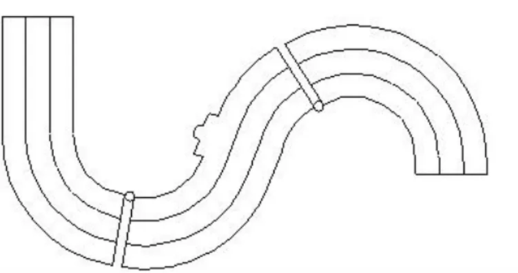
In the direction of the joint, due to the design of the expansion joint in plan view, only a 50 mm relative longitudinal displacement is allowed when the displacement perpendicular to the joint is less than 150 mm. The relative displacement is not restrained when the relative displacement perpendicular to the joint is greater than 150 mm (Figure 2).
Figure 2. Plan view of the expansion joint. The design prevents important relative transverse moves.
An investigation on the materials of the building shows that the quality of the concrete and the steel re-bars is good and better than required in the design, with a mean fc = 37 MPa and a 95% lower prediction of 25 MPa. The quality of the steel re-bars was also correct, with yield strength a few percentage below the nominal value, meaning a few percentage higher than the design value. Numerous pictures of the construction stage allowed checking that the rebars had been placed in number and position according to drawings. The infills in the frames are made of very low strength concrete blocks. Due to this low strength, they have been ignored in models.
2 ASSESSMENT OF THE STRUCTURE BY LINEAR ELASTIC MODAL SUPERPOSITION ANALYSIS
The first assessment of the structure is made using the linear elastic modal superposition analysis, assuming a behaviour factor q = 2, as defined in Eurocode 8 for irregular moment resisting frame structure. This required the construction of a numerical model of each individual block of the structure, which was made using the SAP2000 software. All action effects have been computed: axial force N and bending moments M1 and M2 in all beams and columns, vertical and horizontal shear in all beams and columns. These actions effects have been compared to the resistance of the structural elements, taking into account the effect of interaction between N, M1 and M2 on the elements resistance. A safety factor was established for all elements and all types of member forces.
From this analysis, it can be concluded that the structure has 2 serious problems, but also some positive aspects.
The first problem is that the structure is significantly under-designed, at least in a standard design approach: many structural elements possess less than 20% of the required resistance in a standard design process. Some facts however indicate that the elasto-plastic behaviour of the structures might be good: “Factors of safety” in shear (ratio strength/action effect in structural elements) are in general higher than those in bending, which means that the building may offer a global ductile behaviour since plastic bending would take place before fragile failures in shear. The main resisting frames in the longitudinal direction are the interior ones; they could be a primary resisting system, the façade frames being secondary, so that their bad design could be without effect, if they are flexible enough to remain elastic during elasto-plastic deformation of the interior frames. Non-linear elasto-plastic analysis made in the final stage of the study will indeed demonstrate the ability of the building to resist successfully the design earthquake and the absence of unacceptable weak points in the reconnected structure, to determine the degree of structural damage (rotation demand/supply ratios being used as damage indices).
The second problem are potential fall of many storeys in the vicinity of the expansion joints: beams are supported on corbels over the expansion joints and the displacements of one block, which reach 250 to 500 mm in the upper storeys, exceed by far the joint clearance (50 mm) and the dimensions of the supporting corbels (100 mm). In addition to pounding, the design earthquake as well as the service earthquake would lead to beams loosing supports and floors falling in the vicinity of the expansion joints (Figure 3). However the computed displacements are in the normal range for a well-designed structure. Moreover, the limitation of damages under the service earthquake (frequent earthquake, expected to take place with higher probability during the life of the structure) is also not a problem, since under the service earthquake (40% of the design earthquake), the relative inter storey drift is between 0,08 % and 0,24 % of the storey height, less than the limitation for brittle partitions (0,6 %).
Figure 3. Beams loosing support at expansion joint.
Pounding may be acceptable, due to the fact that beams in adjacent blocks are at the same levels, but separation of blocks and the consequent failure and fall down of rows of rooms is unacceptable. The problem of too wide separations between the building blocks during an earthquake has to be solved. One solution would consist in duplicating the columns at the expansion joints, but this is difficult to achieve while keeping the building in operation. Another solution consists in closing the joints in order to prevent large relative displacements between the blocks. A proper “re-connection” of the 3 blocks constituting the structure has been defined.
3 ANALYSIS OF THE RECONNECTION PROBLEM
3.1 Introduction
Different characteristics of connection systems are tested numerically in order to select the best option. Blocking the dilatation joints result in an increase in the hyperstaticity (redundancy) of the building allowing a better redistribution of action effects in the structure and reducing the risk of local mechanisms. But the stiffness of the structure may also be increased, as it would work as a whole and not as three distinct parts. The plot at Figure 4 shows the increase of periods in "Blocking Case (1)" defined hereunder.
Two steps have been realised in the analysis of the structure by numerical modelling:
1. Two preliminary studies on the influence of the reconnection type and of the distribution over the height of the structure.
2. The modelling of a set of situations, which appeared as best options for detailed design of connections, provides better evaluation of the forces in the connections.
3.2 Modelling of the connection
The deformation of the structure is expressed by the three displacements and the three rotations at each node (six degrees of freedom per node)- see Figure 5. A perfect blocking of the joints results in imposing the same displacements and rotations to both sides of the cut. The hypothesis of perfect blocking means that the designed solution is able to transfer axial forces, shear forces and bending moments (about a horizontal and a vertical axis in the joint), which may be more than needed for the intended objective.
Figure 5. Representation of the six degrees of freedom at the nodes of the structure.
In the analysis, the various forces at points of interaction between blocks of the building are evaluated. Concerning the bending moment about a horizontal axis parallel to the joint, designing the assembly to transmit totally the beams bending moments is more difficult and expensive than designing a system which behaves essentially as a hinge, while it is not sure that designing the assembly to transmit moments makes a great difference for what concerns the global behaviour of the reunited structure. Both cases (perfect transmission and perfect hinges) are studied in order to be able to decide.
3.3 Analysis of a reconnection applied over the complete width
A first study using dynamic elastic analysis (modal superposition) was realized for different degrees of reconnection but with reconnection applied in the 4 lines of longitudinal frames - see Figure 6. For practical reasons, the intervention should not be carried out neither in the 18th storey nor in the lower 3 stories (just
refurbished), nor at the ceiling of the 17th storey to avoid disturbances during intervention.
Several combinations of blocked stories with different imposed restraints have been considered. 1. All stories blocked with perfect blockings (completely fixed);
2. All stories blocked with hinge blockings (hinges of horizontal axis); 3. Same as (1) but stories under 5th storey are not blocked;
4. Same as (1) but stories under 6th and over 17th are not blocked;
5. The blocked storeys are the 6th, 7th, 9th, 11th, 13th, 15th, 16th and 17th;
6. Like (1), without transmission of torsion through beams; 7. No bending or torsion moments transmitted.
From the analysis, it appears that:
− The bending restraint in the joint does not influence much (5% in average) the distribution of the other internal forces.
− The maximum values of the internal forces are not very sensitive to the blocking case, if comparable quantities are compared. There are stiff points in the lower stories that modify significantly the distribution of the forces in the lower part of the building, excepted for these particular zones, the maximum forces don’t vary much from one case to another. The comparison of Blocking Cases (1) and (2) or (6) or (7) shows that the important parameter is the equality of translational displacements at the connecting nodes (2 horizontal, 1 vertical), not the degree of connection. Transmitting local bending moments or torsion moments does not change the axial and shear forces transmitted.
− The blocking case (5), imagined to satisfy the usage conditions, reveals two advantages: the lower storeys are not reconnected, avoiding important concentrated forces resulting from the stiff points; the number of reconnected storeys is reduced in comparison to a complete reconnection (only 7 or 8 storeys out of the 18 storeys are reconnected) even if the values of the reconnection forces at one storey increase and are more difficult to transmit.
− The connection should be able to transmit as maximum values the following total forces at one storey level (sum of the forces at 4 reconnecting points in the model) : axial forces (tension and compression) of 3500 kN for joint 1( inside frame) and 2600 kN for joint 2 (façade frame); Horizontal shear forces of 2200 kN for joint 1 and 1000 kN for joint 2;Vertical shear forces of 900 kN for joint 1 and 700 kN for joint 2; bending moment of ±1900 kN.m for joint 1 and ±1500 kN.m for joint 2, if a reconnection including bending moment is planned. These orders of magnitude of reconnection forces are manageable ones, meaning that reasonable design solutions are possible.
The number of reconnected storey could still be reduced, coming down to only one on every 3 storeys, but then the values of the reconnection forces at one storey would increase and be more difficult to transmit. A detailed design is needed to decide.
3.4 Stresses in the concrete and in the rebars
The results indicate that the reconnection at 4 points (1 to 4 at Figure 6), which creates a diaphragm with high continuous stiffness, "call" high bending moments of vertical axis in the “beam” diaphragm. This generates high stresses in the section of the diaphragm at the joint. A reconnection allowing a relative rotation of vertical axis between blocks around a vertical axis would obviate these high bending stresses in the diaphragm. Another potential positive influence of a “hinged” reconnection of blocks may be the greater flexibility in that case than in a rigid reconnection. Increasing periods of the structure would correspond to reduce pseudo acceleration and base shear.
3.5 Analysis of a reconnection allowing relative rotations of blocks
Two different connecting cases are analysed:
- With the hinges positioned on the facade beams, on the interior side of the curve for joint 1 and on the exterior side of the curve for joint 2.
Figure 7. “Hinged” reconnection with hinges positioned on the interior side of curves.
The results of the analysis indicate that:
1. Forces at the reconnection point are lower than in the case where all 4 points are connected. The global reconnection forces are subsequently much lower (about 3 times lower).
2. Forces at reconnection are lower when hinges are in the interior side of the curves.
3. The relative displacements between points situated on both sides of the joints are at most equal to 50mm, which is less than the 50mm clearance at the expansion joints. These displacements are smaller if the hinge point is interior to the structure. If the connecting point is 2, than the displacement is at most 33 mm.
Conclusion 1 corresponds to 2 facts. First, the choice of a “hinged” reconnection of blocks brings the bending moment of vertical axis at the joint to zero, so that only axial forces parallel and perpendicular to the joint exist. Secondly, the more flexible global system has higher period, which reduces the global shear applied to the structure by the earthquake.
Conclusion 2 probably corresponds to the fact that the reconnection at the interior side involves less eccentricity in transmission of interaction forces, so that forces are lower.
The relative displacements at the points which do not belong to the vertical “hinged” reconnection are low, due to the fact that they are only a sub-product of rotations at that “hinged” reconnection.
3.6 Levels at which the reconnections are made
All cases analysed in a second set of elastic analysis (modal superposition) correspond to the hinged reconnection of Figure 8. This choice is justified by the fact that this positioning correspond to the lower forces in the connections and by the fact that the beams of the main earthquake resisting structure are the interior ones; also, because these beams are connected to columns of big sections complying with “strong columns- weak beams” design, reconnection is more favourable at interior beams than at exterior ones.
Figure 8. Position of hinged reconnection in the refined evaluation of connections design forces.
Various hypotheses are tested concerning the storey levels where the reconnection is applied. Three reasons explain this focus:
- The economy involves that reconnection is not realised at more storeys than necessary;
- The owner of the building wishes to keep the building in use during the operation of reconnection; so he does not wish intervention at levels which are public in the daily use of the building; this is for instance the case for the lower storeys.
- Moreover, the owner does not wish to have reconnection done at some levels that had been recently refurbished, because the reconnection operation would require taking out part of that work.
The different reconnection cases considered are:
1. Storeys under the 5th storey are not reconnected. In the other storeys, there is reconnection by means of a
hinge transmitting axial force, vertical and horizontal shear.
2. Stories under the 6th storey and over the 17th storey are not reconnected. In the other storeys, there is
reconnection by means of a hinge transmitting axial force, vertical and horizontal shear.
3. Reconnection is realized at the 6th, 7th, 9th, 11th, 13th, 15th, 16th and 17th storey’s by means of a hinge
transmitting axial force, vertical and horizontal shear.
3.7 Interaction between blocks at corbels
The interaction between blocks of the building takes place: − At the blockings defined above;
− At all the corbels (they are supports of the beams of the neighbouring block, when the force transmitted is a compression).
However, as the force transmitted at the support can be tension or compression, the case where no contact exists at the corbels needs also be studied. So, for each of the blocking case defined above, two circumstances are studied:
− One in which the interaction between blocks of the building takes place only at the blockings defined above and in the 6 ways defined above. There is no relation between displacements at other points (corbels).
− One in which the interaction between blocks of the building takes place at the blockings defined above, in the 6 ways defined above, and also at all the corbels, where an equal vertical displacement is imposed. The real behaviour at corbels is in between these 2 situations and consideration has to be given to the results of both analyses in order to check resistances and deformations.
3.8 Results of the analysis
The result of the analysis is a decision on the reconnection scheme selected. It corresponds to the distribution of connecting devices. One example of distribution of forces is given at Figure 9.
Figure 9. Distribution of tension forces in connection corresponding to reconnection scheme (3).
The forces resulting from the bending moment of vertical axis between blocks exist only if a bending resistance is provided. If the reconnecting system is a perfect hinge, the bending moment of vertical axis
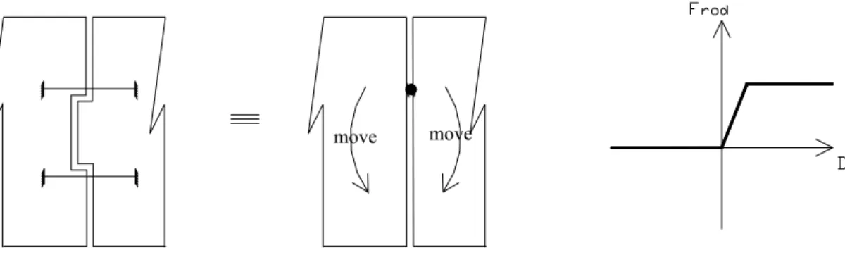
between blocks is zero and only axial forces (N and V) between blocks exist. It was concluded that the design of reconnection should not provide bending resistance of vertical axis between blocks, which raise the practical problem of making a civil engineering design of what should behave as a vertical axis of rotation. A way to materialize this free relative rotation move between blocks consist in connecting the 2 interiors frames over the expansion joints by means of long rods connected to the concrete frame in such a way that they are activated in tension only. Then, only one rod is active (in tension) in the presence of a rotation of vertical axis at the joint. This rod slows down the separation move between blocks, but does not interfere (in fact, create, a bending moment). Also to avoid carrying compression at the expansion joints, the gaps in those joints are not filled with any material. There can be a relative rotation (Figure 10) under seismic action: the hinge point is at the connecting rod under tension and the relative movement is on the "compression" side; there the existing gap is wide enough to allow for free relative rotations between blocks of the value and displacement previously computed in the first set of dynamic modal analysis. Also to avoid carrying compression at the expansion joints, the gaps in those joints are not filled with any material.
Figure 10. Principle of reconnection using long rods and how they achieve a “hinged” connection. Force-Elongation curves of rods.
The long rods are 5m long Dywidag bars. These ones have been selected because they are provided with a special type of thread that does not create stress concentrations in the bars, so that the rod connections are more resistant than the bars themselves. This “capacity design” was retained to prevent failure in the rod in case some yielding would take place. In principle, the design of the section is such that there should not be such yielding, but this capacity design concept was thought necessary to mitigate the uncertainties of the analysis.
For axial forces perpendicular to the expansion joint: on the tension side, forces are based on average values and on the compression side, the resistance is equal to zero. For shear forces (parallel to the joint), a condition of 0 relative displacement is kept.
move move
Figure 12. Rods passing through transverse beam adjacent to expansion joint.
4 PUSHOVER ANALYSIS.
4.1 Peculiarity of Moment-Rotation relationships.
The linear modal superposition analysis failed to demonstrate the ability of the building to resist successfully the design earthquake. A non linear analysis was needed to achieve such a demonstration before any decision on the installation of a reconnection system. It was decided to perform non linear static “pushover” analysis, using the well referred FEMA 273 procedure.
Besides of the standard difficulties of this type of analysis in a structure comprising 7000 individual column and beam elements, a special feature of the structure had to be considered. It was noted during the verification of the location of the plastic hinge at the beam ends that reinforcement development lengths do not all meet ACI 318M-95 requirements: anchorage length are lower than the one required for a portion of the total beam reinforcement, the rest being well anchored.
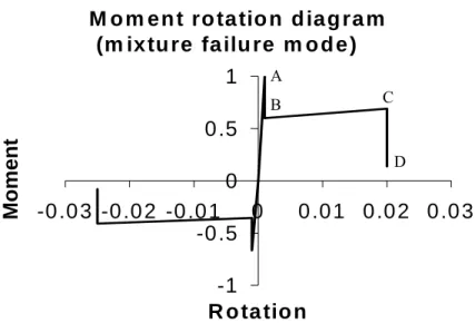
In the FEMA-273 document no such intermediate situation is foreseen: a plastic hinge is either governed by pure flexural failure or by pure anchorage failure. It was decided to define a behaviour intermediate between these 2 failure modes. A plastic moment that corresponds to brittle failure mode was computed: once the bond failure occurs, the resistance does not fall down to zero, but to a plastic moment that corresponds to the reinforcement portion that comply with anchorage length requirements (point B of Figure 13; as these reinforcement are continuous, the hypothesis is licit. The rotation capacity at point C of the figure is obtained following FEMA-273 for flexural failure mode. Between B and C, the behaviour is ductile. The point C represents the steel failure of the well-anchored bars and at this point the resistance falls down to zero. This representation of the local M-Φ relationship may seem complicated, but is necessary: the higher resistance M has to be considered, because if the beam is too strong, a “weak columns-strong beams” mechanism can take place. Skipping this highest local resistance can then give a false impression about ductility of the structure.
4.2 Results of the pushover analysis.
For each of the non-linear push-over analyses, a first output provided is a push over analysis curve, relation between base shear and roof top displacement up to the performance point. The performance point represents the maximum non-linear range undergone by the building under the expected earthquake. The series of pushover performed on a building reconnected with flexible connections were stopped at a maximum roof displacement equal to 1.2 times the target displacement – see examples at Figure 14. If any
structural element looses its residual resistance, point D in Figure 13, before reaching 1.2 times the target displacement, it is considered that the structure collapses and the analysis is stopped.
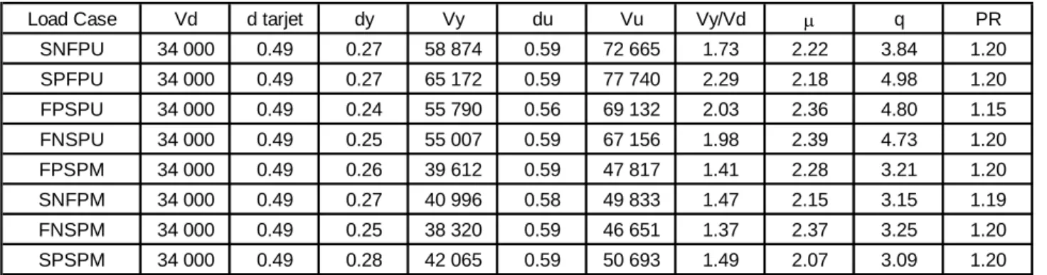
The non-linear push-over analyses provides a second series of output in term of parameters :
- The base shear at first yield V1y and α1 multiplier of the horizontal loads that produce the first yield of
the structure.
- The design structural over-strength Ωd, ratio of design base shear Vd to first yield base shear V1y
Ωd= α1y / αd αd = multiplier of horizontal load related with the design action
- µ = du / dy , ratio of ultimate to yield displacement.
- The behaviour factor q, approximated for long period structures as: q= µ Ωd αu / α1y = µ αu / αd
- The global ductility supply, ultimate shear to design base shear ratios.
- PR or performance ratio is the ratio of computed to assumed behaviour factor; it can be interpreted as the ratio between the response spectrum capacity to the coded elastic response spectrum or the ratio of the maximum top displacement du to the target displacement dtarget. A value higher than one means that the
performance objective is reached.
The push-over analysis also provides a list of the damaged elements and their level of damage and drawings of the plastic mechanism at the performance point for the most damaging cases.
Examples of pushover curves and the equivalent bilinear diagrams are shown at Figures 14. The horizontal black line in these graphs represents the design base shear Vd. Its value is equal to 34.000 kN.
M o m e n t ro ta tio n d ia g ra m
(m ix tu re fa ilu re m o d e )
-1
-0 .5
0
0 .5
1
-0 .0 3 -0 .0 2 -0 .0 1
0
0 .0 1 0 .0 2 0 .0 3
R o ta tio n
Moment
A B C DFigure 13. Moment-Rotation behaviour used in case of possible bond failure of part of the reinforcements.
F
Load Case Vd d tarjet dy Vy du Vu Vy/Vd µ q PR SNFPU 34 000 0.49 0.27 58 874 0.59 72 665 1.73 2.22 3.84 1.20 SPFPU 34 000 0.49 0.27 65 172 0.59 77 740 2.29 2.18 4.98 1.20 FPSPU 34 000 0.49 0.24 55 790 0.56 69 132 2.03 2.36 4.80 1.15 FNSPU 34 000 0.49 0.25 55 007 0.59 67 156 1.98 2.39 4.73 1.20 FPSPM 34 000 0.49 0.26 39 612 0.59 47 817 1.41 2.28 3.21 1.20 SNFPM 34 000 0.49 0.27 40 996 0.58 49 833 1.47 2.15 3.15 1.19 FNSPM 34 000 0.49 0.25 38 320 0.59 46 651 1.37 2.37 3.25 1.20 SPSPM 34 000 0.49 0.28 42 065 0.59 50 693 1.49 2.07 3.09 1.20
Table 1. Results of pushover on structure reconnected by flexible connections.
4.3 Design forces in the reconnection system.
The pushover analysis were also used to compare rigid and flexible reconnections. In Table 2, the maximum tension forces (F) in the connecting bars given by the pushover analysis in the hypothesis of a rigid/flexible reconnection are provided, for one particular joint (joint 1 or J1) and one particular horizontal position R2 of the connection. R2 and R3 are respectively the internal and external positions of the two central longitudinal beams perpendicular to the expansion joint. Three letters indicates the vertical position, S11 meaning for instance storey 11.
Connection at Joint1 Connection in row R2 J1R2
Axial force in connection (kN) Case of rigid reconnection in R2 and in R3
Axial force in connection (kN) Case of flexible reconnection in R2 and in R3 Storey S06 17373 2522 S07 6900 2106 S09 2469 490 S11 2007 560 S13 1733 584 S15 2092 1191 S16 1999 1485 S17 1986
Table 2. Axial forces in connections.
The results clearly show that rigidity attracts forces and validates the option made of a flexible reconnection using long rods. This type of connection contributes to a reduction of the forces in the connections, probably because it reduces the asymmetry of the building and the concentration of internal loads in some parts of the structure. With the beneficial elongation of the flexible joint connections, the building performs better than a fully continuous structure. It can be estimated that this is due in part to the local flexibility of the connections. Because of their length, the bars can elongate elastically up to 17,6 mm or 24,1 mm, depending on the connection considered.The elongations in the bars are much lower than the 100 mm limiting value of relative displacement allowed by the columns corbels. They range between 0 and a maximum 39 mm. Most of the connections (20 over 28) remain elastic for all loading cases. The 8 remaining connections are always those situated in the three lower or two upper connected floors.
5 CONCLUSIONS
A practical case of interaction between adjacent buildings was studied. Different reconnection hypothesis were considered, ranging from fixing totally each block to the adjacent one to more flexible options leaving some free relative move between blocks. The degrees of freedom of the joint reconnections were observed to be an important parameter: an increase in stiffness could not be avoided, but it had to be defined in order not to induce too high additional internal forces in the structure. The solution found leaves a free relative
rotational move between adjacent building blocks. This avoids the need to reconnect the façade frames and to carry high forces at that place. The relative translational move should not totally be prevented; some flexibility exists, so that the forces at the connection between blocks do not become uselessly high. The relative move has to be limited; thus the connection has to be springs. These springs work essentially elastically, so that no or little permanent relative displacements exist between blocks after an earthquake. Based on these concepts, an adapted reconnection was defined. It uses long tie rods connecting the interior longitudinal frames of the building. This reconnection, which need not be placed at every storey is now installed.
6 REFERENCES
ACI Committee 318. Building Code Requirements for Structural Concrete (ACI 318M-95) and Commentary (1995). Eurocode 8 – ENV-1998 (year 1994).


![Risiko- & [und] Schutzfaktoren der psychischen Gesundheit humanitärer Einsatzhelfer : eine systematische Literaturübersicht](data:image/gif;base64,R0lGODlhAQABAIAAAP///wAAACH5BAEAAAAALAAAAAABAAEAAAICRAEAOw==)